
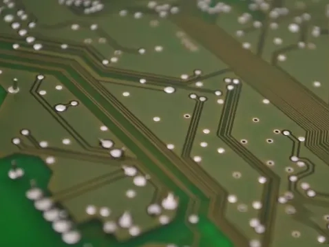
في السرعة الحديثة, إلكترونيات عالية الكثافة, a precisely engineered لوحة الدوائر المطبوعة (ثنائي الفينيل متعدد الكلور) بمثابة الإطار المركزي. كتقنية تركيب السطح (سمت) يضع الآلاف من المكونات المصغرة داخل مساحة محدودة, a fundamental safety question arises: what is the minimum electrical clearance required between adjacent component pads (lands) to ensure reliable operation?
In serious engineering, relying on “rules of thumb” or intuition for this answer is insufficient and potentially hazardous. The true answer lies within a rigorous scientific framework, guided by the authoritative standards published by IPC (Association Connecting Electronics Industries). This guide will navigate the core principles of IPC-2221 and IPC-610, cutting through the complexities of voltage, environment, and materials to reveal the complete logic and practical methodology for defining this critical “safety distance.”
أنا. Core Concept: Electrical Clearance – The “Safety Buffer” for PCB Reliability
Electrical clearance, in simplest terms, is the shortest straight-line distance in air between two unconnected conductive parts. In the context of مركبات ثنائي الفينيل متعدد الكلور, it specifically refers to the insulated space between adjacent solder pads, traces, or copper areas.
Its physical significance and primary mission are to prevent air dielectric breakdown under high electric fields, thereby avoiding arcs, short circuits, or leakage currents. Particularly in harsh operating environments—such as those with high temperature, high humidity, conductive dust contamination, or high altitude—insufficient clearance drastically reduces insulation strength. This can become a critical point of failure, leading to premature product failure or even safety hazards. لذلك, it is not merely a geometric parameter but an essential “safety buffer” ensuring the long-term stability of the PCB and the final printed circuit board assembly (ثنائي الفينيل متعدد الكلور).
ثانيا. The Design Source: IPC-2221 – The “Decision Map” for Scientific Calculation
IPC-2221, “Generic Standard on Printed Board Design,” is a foundational document in تصميم ثنائي الفينيل متعدد الكلور. It does not arbitrarily dictate a universal value but establishes a scientific decision-making framework based on multi-variable assessment. Understanding this framework is the first step beyond empiricism.
The Four Key Variables Determining Minimum Electrical Clearance:
-
Peak Working Voltage: The maximum potential difference between adjacent points in the circuit. This is the core driver of the requirement—higher voltage necessitates greater “safety distance.”
-
Pollution Degree: The expected cleanliness of the product’s operating environment. IPC standards classify this from 1 ل 4. Higher degrees indicate environments potentially containing conductive dust, condensation, or salt spray, requiring increased clearance to mitigate tracking risks.
-
PCB Material Group: Categorized by the material’s Comparative Tracking Index (CTI), which measures a material’s surface resistance to forming conductive leakage paths. Common FR-4 typically falls into Group III (CTI ≥ 100V), while high-performance materials may achieve Group I (CTI ≥ 600 فولت).
-
Application Altitude: Higher altitude means thinner air and reduced insulation strength. For equipment operating above 2000 meters, the tabulated clearance value must be multiplied by an altitude correction factor greater than 1.
Application Process: From Table Lookup to Final Value
IPC-2221 provides detailed tables outlining “minimum internal” و “minimum external” clearance for various combinations of these variables. For SMT component pads on the surface, we focus on “external clearance.”
The decision process can be simplified as:
Step 1: Parameter Definition. Determine the highest working voltage (DC or AC peak) between adjacent pad nets; assess the product’s use environment to set the Pollution Degree (often preset to Degree 2 for consumer indoor electronics); confirm the CTI group of the PCB base material; identify the maximum operating altitude.
Step 2: Obtain Base Value via Table Lookup. Using the parameters above, cross-reference the appropriate table in IPC-2221 (على سبيل المثال, IPC-2221B) to find the theoretical minimum electrical clearance.
To illustrate the positive correlation between voltage and clearance, here is an example table based on the logic of the standard:
*(Crucial Note: For actual design, you must consult the latest version of the IPC-2221 tables. This example is for trend illustration only.)*
| Peak Working Voltage (V) | Minimum External Electrical Clearance Reference (مم) for Pollution Degree 2, Material Group III (Typical FR-4) |
|---|---|
| ≤ 15 | 0.10 |
| 50 | 0.13 |
| 100 | 0.18 |
| 150 | 0.25 |
| 300 | 0.50 |
| 500 | 1.00 |
*Data logic derived from the IPC-2221 design standard framework. Specific values must be verified against the current standard.*
Step 3: Altitude Correction. If applicable, multiply the tabled value by the provided correction factor.
Key Takeaway #1: To the question “What is the minimum SMT pad clearance?”, the correct answer per IPC-2221 is: “It depends on your product’s voltage, environment, مواد, and altitude.” For common 3.3V or 5V low-voltage digital circuits in benign environments, it could be as low as ~0.1mm, but this is not an unconditional “universal value.”
ثالثا. The Manufacturing Gauge: IPC-610 – The “Guardian” of Design Intent
If IPC-2221 provides the rules for designers, then IPC-610, “Acceptability of Electronic Assemblies,” is the “grading” standard for manufacturing and ضبط الجودة personnel. It ensures the “safety buffer” defined during design is not compromised during complex PCBA manufacturing processes.
IPC-610H does not specify design clearance values directly. بدلاً من, it uses the design documentation (which should follow IPC-2221) as the gold standard for conformance assessment:
-
Preventing Solder Bridging: Any solder bridge formed between non-connected pads that violates the designed electrical clearance is considered a defect. This is the first line of defense for guarding clearance in SMT processes.
-
Controlling Solder Residue: Solder residues like solder balls must also maintain a distance from themselves and adjacent conductors that meets the minimum electrical clearance specified in the design files.
-
Bare Board Verification: Before SMT assembly begins, IPC-610 also requires confirmation that the bare PCB’s line width and spacing (including pad spacing) conform to the design. This means your الشركة المصنعة لثنائي الفينيل متعدد الكلور must be capable of consistently achieving the clearance value you calculated based on IPC-2221.
Key Takeaway #2: IPC-610H acts as the “guardian” on the manufacturing side. It mandates that all subsequent processes—SMT printing, placement, reflow soldering—must not encroach upon the designed safety boundary (defined by standards like IPC-2221) through any defect, such as bridging or solder balls.
رابعا. From Standard to Practice: Cross-Verification with PCB Process, مواد, and Safety Regulations
Mastering the standards is just the first step. Excellent engineers must cross-verify theoretical requirements with real-world PCB process capabilities, material properties, and end-product safety regulations to arrive at a truly manufacturable and reliable design value.
Verification 1: Process Capability Sets the Physical Floor
IPC standards give the “theoretical safe value,” while manufacturing processes define the “physically achievable value.”
-
PCB Fabrication Limits: Every PCB manufacturer has a stated process capability, typically expressed as “minimum line width/space,” على سبيل المثال, “4/4 ميل” (~0.1/0.1mm). Even if IPC-2221 calculation only requires 0.08mm, designing below the fabricator’s capability will cause yield to plummet or make production impossible. لذلك: Actual Design Clearance ≥ Max(IPC Theoretical Value, PCB Fab Capability Limit).
-
SMT Assembly Challenges: This is where electrical clearance is most frequently compromised. For fine-pitch components (على سبيل المثال, ICs with pitch <0.5مم), precise stencil aperture design, solder paste volume control (relying on SPI equipment), and optimized reflow profiles are critical to prevent molten solder from bridging due to surface tension, which erodes clearance.
Verification 2: Specific Application and Material Requirements
-
High Voltage & Safety Certification: For products like power supplies, industrial controls, or automotive electronics, basic electrical clearance must often be supplemented to meet higher creepage distance requirements from safety standards like IEC or UL. This may require tactics like adding slots, increasing solder mask thickness, or using higher CTI materials. Clearly communicating these high-voltage requirements during PCB fabrication inquiries is essential.
-
Micro-component Reliability: With ultra-small components such as 01005 أو 0201 مكونات الشريحة, the physical space between pads is minimal. Sufficient clearance here is not just for electrical insulation but is also the physical foundation for ensuring proper solder joint formation and preventing defects like “tombstoning.”
V. Ultimate Practical Guide: A Systematic Checklist for Engineers
The next time you need to determine or review pad-to-pad electrical clearance, follow this systematic workflow:
-
Define Requirements: Identify the highest working voltage between circuit nets, the product’s application environment (Pollution Degree), and altitude.
-
Consult the Standard: Using the latest IPC-2221 standard and your مادة ثنائي الفينيل متعدد الكلور group, perform a table lookup to obtain the theoretical minimum electrical clearance value أ.
-
Benchmark Process Capability: Consult your PCB supplier or review their process specifications to obtain their reliable minimum feature spacing capability B.
-
Verify Safety Regulations: If the product requires certifications (على سبيل المثال, أول, اللجنة الانتخابية المستقلة), check the specific clearance and creepage requirements from those standards, value ج.
-
Final Design Decision: The final adopted design value = Max (أ, B, ج). This value must be clearly annotated on the PCB design documents.
-
تصنيع & Acceptance: Provide documents containing this design value to your PCBA supplier. Use the clauses in IPC-610 regarding solder bridging and residue as the mutual acceptance criteria.
خاتمة
The minimum electrical clearance between SMT component pads is a multidisciplinary challenge integrating electrical safety theory, materials science, environmental engineering, and advanced manufacturing processes. It demands that designers move beyond simplistic empirical numbers and embrace a systematic engineering mindset—guided by IPC standards, grounded in process capability, and bounded by safety regulations. Only then can the designed PCB and PCBA reliably uphold the product’s function and safety throughout its lifecycle, ensuring a competitive edge.
