

Einführung
In 5G communications, microwave radar, and high-speed data transmission, signal integrity and transmission speed determine device success. Standard PCB -Materialien like FR4 often cause signal attenuation at high frequencies due to dielectric loss. For these demanding applications, you need a circuit board with a “golden medium”—Teflon-Leiterplatte. Als Profi Leiterplattenhersteller, UGPCB delivers high-precision Teflon PCBs from 2 Schichten zu 34 layers using advanced production processes.


What is Teflon PCB?
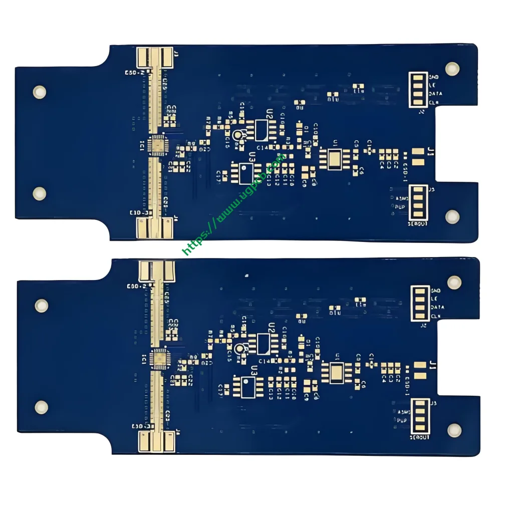
Teflon-Leiterplatte refers to Leiterplatten made with polytetrafluoroethylene (Ptfe, commonly known as Teflon) laminate material. Due to its extremely stable chemical and electrical properties, this material works ideally in high-frequency electronic equipment where frequency performance is critical.
Core Materials and Performance Parameters
Teflon’s exceptional high-frequency performance comes from its unique physical and electrical characteristics. UGPCB manufactures Teflon PCBs with these core specifications:
-
Dielektrizitätskonstante (Dk): 2.0 - - 3.5. This low Dk ensures fast signal propagation with stable values across wide frequency ranges.
-
Dissipationsfaktor (Df): Extremely low (typically below 0.002). Df measures signal loss—lower values mean better signal integrity. UGPCB enforces strict incoming inspection for material Dk/Df to guarantee high-frequency performance.
-
Schichten: 2 layers – 34 Schichten. Whether you need simple double-sided boards or complex 34-layer multilayer PCBs, UGPCB’s professional lamination processes deliver.
-
Brettdicke: 0.1mm – 12mm, meeting diverse power and structural requirements.
-
Kupferdicke: Base copper 0.5oz, finished copper thickness 1oz, balancing current capacity with line precision.
-
Oberflächenbeschaffung: Immersion Gold or ISIG. These flat finishes support the skin effect of high-frequency signals and minimize loss.
Wissenschaftliche Klassifikation
-
Nach Basismaterial: Specialty Material PCB (Organic Resin category – PTFE-based)
-
By Frequency: High Frequency Microwave PCB
-
Durch Struktur: Multilayer Rigid PCB (including hybrid constructions)
-
Durch Anwendung: RF/Microwave Circuit Board
Working Principle and Key Design Points
In microwave high-frequency circuits, signal wavelengths become extremely short during transmission. Teflon-Leiterplatte works by using its ultra-low dielectric constant and loss to confine electromagnetic waves within precisely impedance-controlled traces (Typischerweise 50 oder 75 Ohm), minimizing reflection and attenuation.
Wichtige Designüberlegungen
Two factors matter most when designing UGPCB Teflon PCBs:
-
High RF Line Precision: High-frequency traces like antenna feed lines and microstrips require strict width and spacing control. Small errors cause impedance mismatch. UGPCB uses high-precision etching to ensure accurate RF line formation.
-
Dk/Df Material Selection: Choose materials with Dk values matching your operating frequency. UGPCB helps you select and verify materials like Rogers or Taconic series.
Product Classification and Structure
Teflon PCBs classify by structure and material combination:
-
Pure Teflon PCB: Made entirely from PTFE laminates. These offer maximum stability but cost more. Due to PTFE’s soft nature, they often need special fixtures.
-
Hybrid Teflon PCB: To balance cost and mechanical strength, Teflon+FR4 hybrid construction works well. High-frequency layers use Teflon while other layers use FR4. This requires advanced lamination to match different thermal expansion coefficients. UGPCB has extensive hybrid lamination experience.
UGPCB Production Process and Quality Control
Quality Teflon PCBs require strict process control:
-
Vorbehandlung: Teflon’s low surface energy demands plasma or sodium-naphthalene treatment before drilling to enhance copper adhesion in via holes.
-
Bohren: PTFE’s softness and glass content require different drilling parameters than FR4. We use specialized bits to prevent burrs and rough hole walls.
-
Überzug: After special activation, hole walls achieve strong copper connections.
-
Musterübertragung: High-precision alignment and exposure in cleanroom conditions ensure RF line accuracy.
-
Radierung: We strictly control side etching to maintain trace rectangularity, critical for high-frequency impedance.
-
Qualitätsinspektion: Finished products undergo IPC-A-600 visual inspection and 100% electrical testing, treffen IPC6012 Klasse II oder Klasse III Anforderungen.
Primäranwendungen
With excellent microwave properties, UGPCB Teflon PCBs serve these fields:
-
Telecommunications Infrastructure: Power amplifiers, antenna systems
-
Satellitenkommunikation: Lnbs, transponder modules
-
Automobilradar: 77GHz millimeter-wave radar, collision avoidance systems
-
Luft- und Raumfahrt & Verteidigung: Navigation equipment, elektronische Gegenmaßnahmen
-
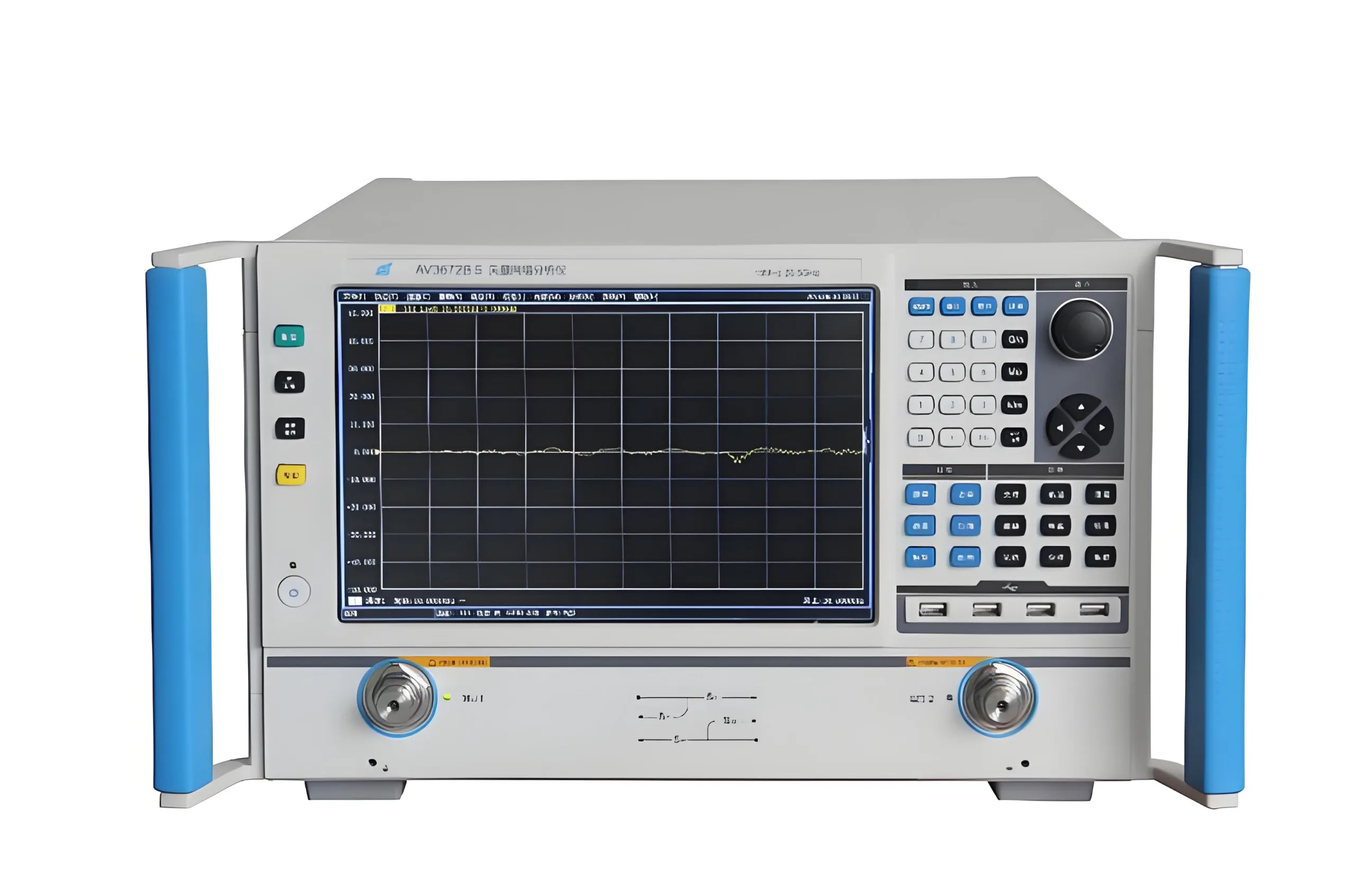
Test Instruments: Network analyzers, high-frequency probes, test fixtures

Why Choose UGPCB for Teflon PCBs?
-
High-Frequency Expertise: We understand Dk/Df impacts on signals. We control everything from material selection through production.
-
High-Multilayer Capability: We handle up to 34 layers of Teflon and hybrid constructions for complex designs.
-
Precision Focus: We specialize in high-accuracy RF lines with impedance tolerance within ±5% or tighter.
-
Quality Certified: We strictly follow IPC6012 Class II/III standards, providing reliable quality assurance.
Handeln Sie noch heute
Great microwave equipment starts with a great Teflon-Leiterplatte. If you need stable, zuverlässig, high-performance PCB solutions for high-frequency applications, UGPCB ist Ihr vertrauenswürdiger Partner.
Do not let material limitations restrict your design possibilities.
[Submit your PCB design files (Gerber) and requirements. Get a professional quote and DFM analysis from UGPCB today!]