
高速デジタル回路と精密アナログシステムの収束で, 絶妙に設計された プリント基板 回路図 製品の生存率を決定します 90% パワーの整合性崩壊に由来する設計障害の.

エンジニアがAltium Designerで37番目のDDR4長さマッチされたトレースをルーティングするとき, インピーダンス レイヤースタックに隠された不連続性は、信号の完全性を静かに分解します. UGPCBシミュレーションデータが明らかになりました: 最適化されていない電力モジュールを備えたPCBは苦しんでいます 62% 故障率, スプリット面テクノロジーを実装するデザインは、ビットエラー率を10〜²に低下させます.
回路の本質: PCB回路図の中核原則 & 進化
配線図からインテリジェントシステムまで
現代の概略図が進化しました インテリジェントエンジニアリングエコシステム:
-
電気ニューラルネットワーク: 組み込む 32 設計ルール (トレース幅/間隔/インピーダンス/クロストークのしきい値); UGPCBの制約マネージャーは同期します 12,000+ ネットワーク
-
クロスドメインコラボレーション: アレグロSI分析が示す ±18psタイミングマージン 6層の重要なパスの場合 HDIボード, Schematic-PCB-Firmware共同最適化が必要です
革新的な設計ツールの進歩
| ツール生成 | 代表的なソフトウェア | 効率ゲイン | UGPCB最適化ケース |
|---|---|---|---|
| 基礎デザイン | プロテル99SE | 1Xベースライン | プロジェクト移行のためのレガシーライブラリの互換性 |
| 高速デザイン | Altiusデザイナー | 3.2x | 動的長さマッチングエラー≤0.01mm |
| システム設計 | ケイデンスアレグロ | 5.7x | 40% 16Gbpsでのアイダイアグラムマージンの改善 |

UGPCBケーススタディ: OrcadからAllegroへの移行は、BGAエスケープルーティングの成功を増やしました 74% に 98%, 開発サイクルを減らす 21 日.
モジュラー設計方法論: 複雑な回路の分解
パワーの完全性: 重要な差別化要因
トポロジ選択式:
h = frac{p_{外}}{p_{外} + p_{SW} + p_{cond}} \Quad Text{(ターゲット>92\%)}
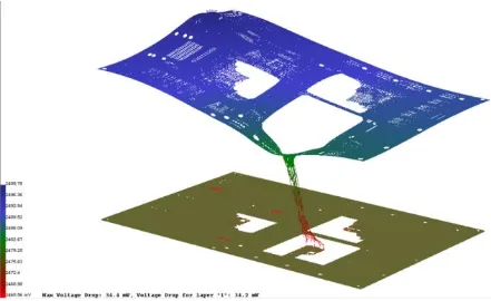
UGPCB 3Dパワーツリー分析:
-
自動車ECUで220MVから35MVに垂れ下がった電圧の垂れ下がった LDO配置最適化
-
ハイブリッドパワープレーン: スプリット/混合平面技術により、リップルが減少しました 67%

高速信号パスの精密制御
インピーダンス制御方程式:
UGPCB実装:
-
微分ペア補正: スキューを達成しました<2100gの光学モジュールのPS
-
EMシールドウォール: 18DB SNRの改善 医学 プリント基板 デジタル/アナログ分離を介して
工業用グレードのデザイン: UGPCB 9 コアテクノロジー
3Dスタックアップアーキテクチャの最適化
最適な8層構成:
L1: 信号 (高速)
L2: Solid GND
L3: 信号 (ストリップライン)
L4: Power
L5: GND
L6: Signal
L7: Power
L8: 信号 (低速)
検証: 12DBμV/M EMIの減少, FCCクラスB認定
製造主導のデザイン (DFM) 精度
UGPCB ±0.025mmプロセス制御:
-
Microviaテクノロジー: 0.1MMレーザードリル, 12:1 アスペクト比
-
銅の厚さ: 2オンスの外層の±10%エッチング許容範囲
-
はんだマスクブリッジ: 0.075MM最小幅はSMTブリッジングを防ぎます
デザインを超えて: UGPCBのフルライフサイクルサービス
信号整合性保証
設計フェーズ: hyperlynx pre-layoutシミュレーションは排除されます 90% リスク
検証フェーズ: TDRテストが保証されます <5% インピーダンス偏差
量産: キーパラメーターコントロールのゴールデンリファレンスデータベース
スマート製造統合


結果: 48-時間のプロトタイプ配信, 99.2% ファーストパス収量
将来のラボ: UGPCBの技術フロンティア
シリコン基板不均一な統合
2.5D TSVインターポーザー:
-
0.3FPGA-HBM統合のMMピッチ相互接続
-
熱抵抗は0.15°C/wに減少しました
AI主導のEDA革命
Neurorouteエンジン:
-
8Xルーティング効率の改善
-
最適化関数:
Min(ΔL, Crosstalk, Via_Count) -
5G MMWaveアンテナアレイに展開されます プリント基板 デザイン