What is a Power Bank Circuit Board?
Basic Functionality
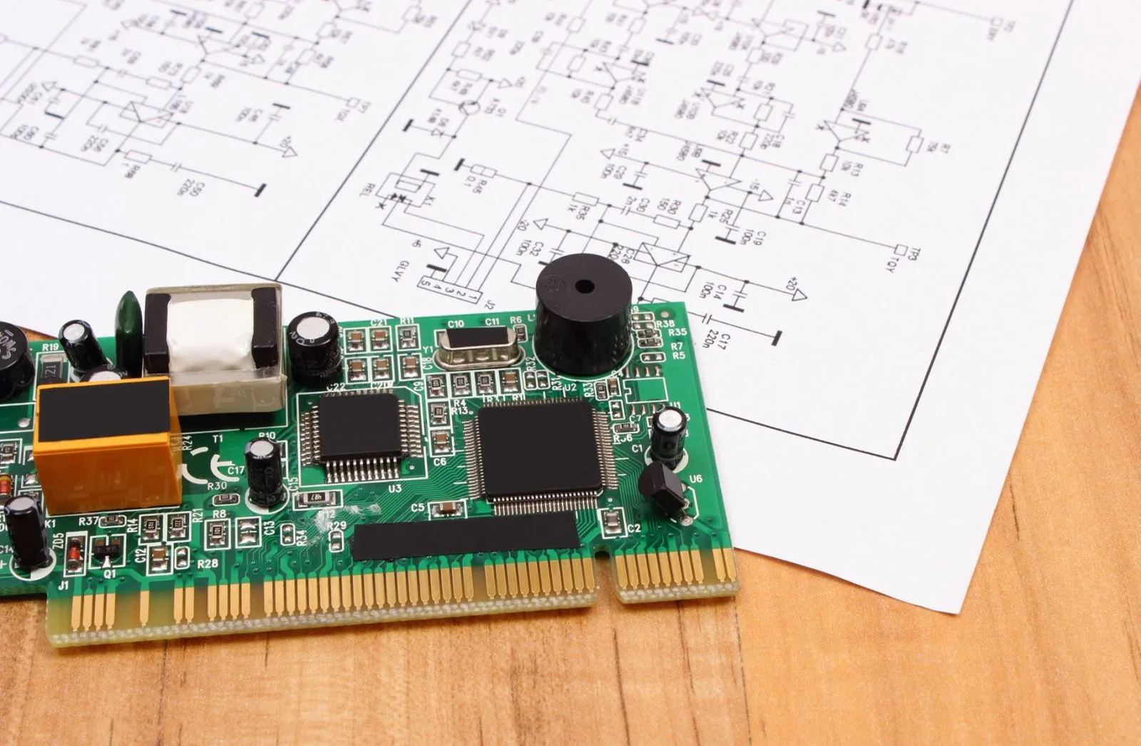
The charging and discharging module integrates the microUSB interface, and the mobile power circuit board can be used to charge other electronic products. The power bank circuit board integrates overcurrent protection, overvoltage protection, and undervoltage protection. The power bank has high precision.
急速充電
Fast Charging for Short
Fast charging refers to a charging method that can make the battery reach or close to a fully charged state within 1 に 2 時間.


