
À l’ère du développement électronique agile, la conception modulaire est la clé du raccourcissement de R&Cycles D. Séparation des systèmes centraux (comme un microcontrôleur ou des modules FPGA multicouches complexes) provenant de cartes de support périphériques atténue les risques de conception. Cependant, the physical connection between the core module and its carrier board often becomes the system’s Achilles’ heel. Comment les ingénieurs peuvent-ils garantir des connexions sécurisées tout en recherchant des performances et une densité élevées ?? Un spécialiste PCB processus connu sous le nom demi-trous plaqués (trous crénelés) apparaît comme une arme secrète pour les industriels, automobile, et applications haute fiabilité.
Le dilemme modulaire: Le paradoxe de la fiabilité des connecteurs
Les connexions de modules traditionnelles reposent sur des embases à broches peu coûteuses ou des connecteurs carte à carte de précision. Les connecteurs à broches sont économiques mais problématiques dans les environnements soumis à des vibrations ou à des cycles thermiques. Mouvement relatif infime (s'inquiéter) au niveau de l'interface de contact peut s'user à travers le placage en or, exposer le nickel ou le cuivre sous-jacent. Selon IPC études, des amplitudes de frottement aussi petites que quelques microns peuvent provoquer ce phénomène. Les métaux exposés s'oxydent, et ces oxydes agissent comme des abrasifs, conduisant à des couches isolantes à haute résistance. Comme décrit dans IPC-9701A (Méthodes de test de performance et exigences de qualification pour les fixations à souder à montage en surface), this “fretting corrosion” can cause contact resistance to skyrocket from milliohms to hundreds or thousands of ohms, provoquant des signaux intermittents ou une défaillance thermique.
Les connecteurs de précision offrent d'excellentes performances mais s'avèrent souvent prohibitifs en raison de leur coût élevé, exigences strictes en matière de tolérance d'usinage des PCB et des boîtiers, et une hauteur de pile verticale importante. Technologie demi-trou plaqué comble cet écart, offrant la fiabilité d'un joint de soudure permanent avec la commodité d'assemblage semblable à celle du SMT.
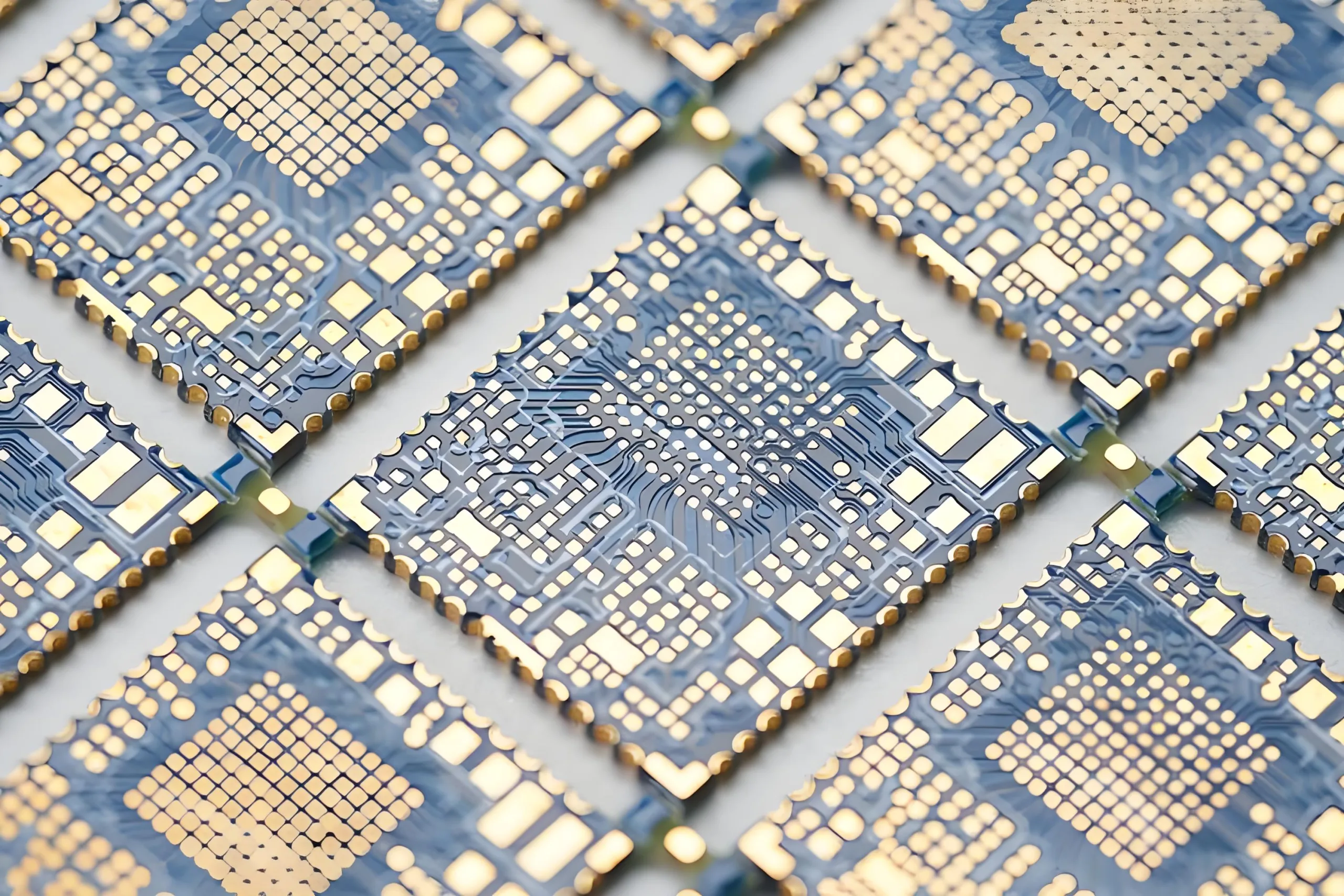
Que sont les trous crénelés? Fabrication de PCB de précision au-delà des apparences
À première vue, un demi-trou de bord de planche ressemble à un via standard coupé en deux par un foret de routage. En réalité, sa fabrication implique un contrôle précis du processus et est classée comme un processus spécial dans Normes IPC.

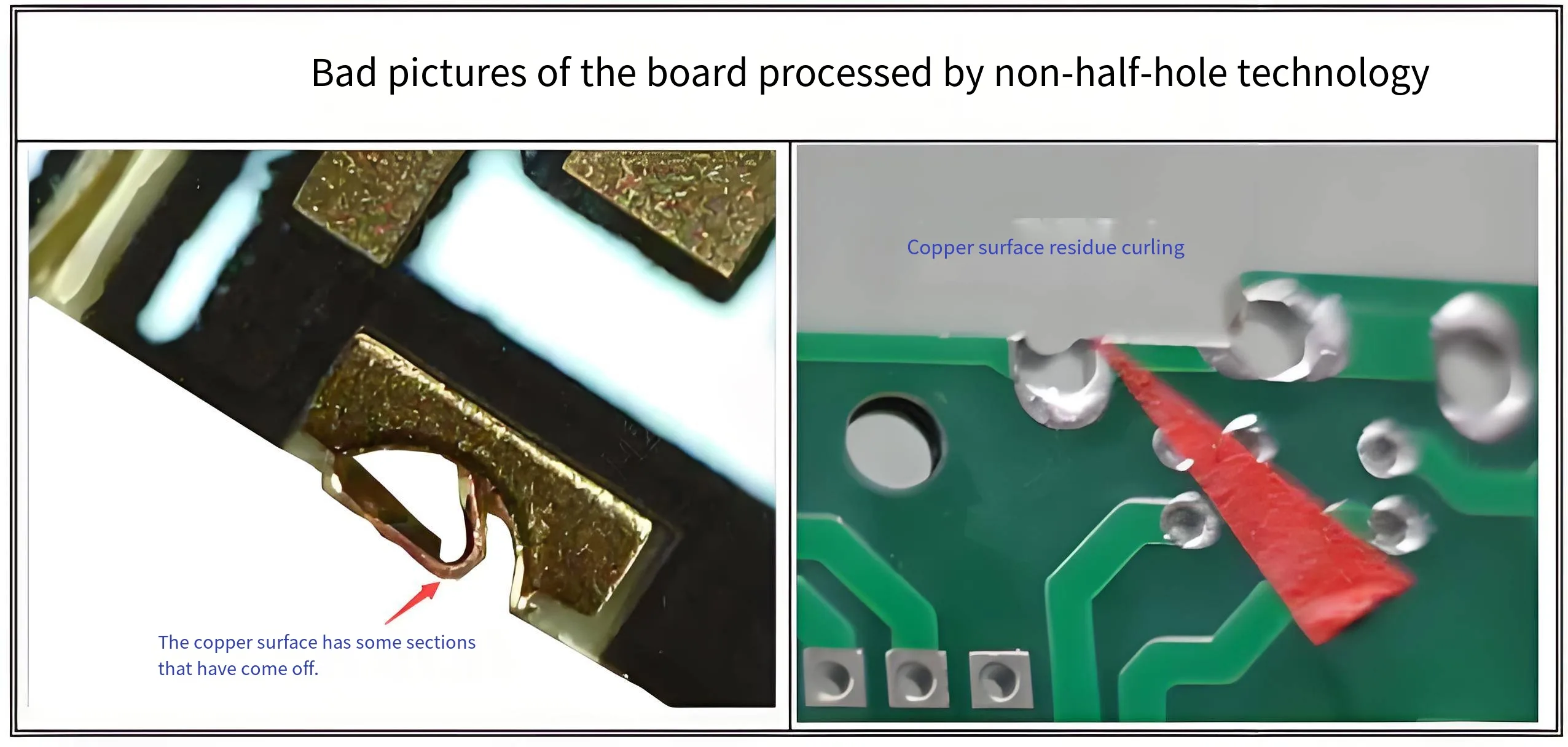
Si le routage du profil PCB standard passe à travers un trou entièrement plaqué, la contrainte mécanique du foret à grande vitesse peut déchirer le corps en cuivre du diélectrique, causing “copper pull-back” or burrs. Par IPC-6012E (Qualification et spécifications de performances pour les cartes imprimées rigides), ces défauts sont conditionnellement ou carrément rejetables car ils interrompent la continuité électrique, et les bavures peuvent provoquer des courts-circuits.

Donc, un processus demi-trou qualifié nécessite des étapes spéciales intégrées dans le flux standard. Primary methods include the “secondary drill method” or “precision depth-controlled routing.” These steps increase manufacturing time and cost but ensure the integrity and smoothness of the copper wall post-cutting, fournir une base solide pour le soudage. This explains why specifying “half-hole process” typically incurs additional engineering and fabrication costs during PCB prototyping or production.
L'art de la conception de circuits imprimés: Géométrie des plots de soudure basée sur les normes IPC
Le succès du soudage d'un module crénelé repose également sur Fabrication de circuits imprimés qualité et conception précise des tampons sur la planche porteuse. Le principe est similaire à la soudure d'un support de puce sans plomb (LCC), visant à favoriser l'action capillaire de la soudure le long de la paroi du demi-trou pour former un filet robuste et inspectable.
IPC-7351C (Exigences génériques pour les normes de conception de montage en surface et de configuration du terrain) fournit le cadre théorique. Le plot correspondant sur la planche porteuse ne doit pas être une simple projection 2D du demi-trou. Une conception optimisée équilibre la connexion électrique, résistance mécanique, et fenêtre de processus.
Les principales recommandations concernant les dimensions des tampons de la carte support sont les suivantes ::
-
Largeur du tampon (X): Correspond généralement ou est légèrement plus grand que le diamètre du demi-trou/la largeur du tampon du module. Une formule de référence:
X = Half-hole Diameter + 0.1mm. Une largeur excessive peut augmenter le risque de pontage. -
Longueur du tampon (Oui) – Toe Extension: Critique pour former le congé de pointe. Le plot doit s'étendre vers l'extérieur sous le module pour fournir de l'espace pour la montée de la soudure.. Les principes IPC suggèrent une extension suffisante pour un ménisque visible. Une valeur empirique de 0.3mm à 0,5 mm est recommandé, 0,5 mm étant idéal pour les retouches manuelles, réparation, et Zone d'intérêt inspection.
-
Longueur du tampon (Oui) – Heel Extension: Le coussinet doit s'étendre vers l'intérieur sous le module pour améliorer le congé du talon et l'ancrage mécanique.. Une valeur de 0.2mm à 0,3 mm est recommandé.
Le choix de la finition de surface est également crucial. Énipique ou ACCEPTER, avec leur appartement, surfaces résistantes à l'oxydation, favorisent grandement le mouillage de la soudure et sont préférés pour le brasage demi-trou de haute qualité.
Le sommet de la fiabilité: From “Separable” to “Unified” Connection Philosophy
The fundamental advantage of castellated holes is transforming the module-to-board interface from a “separable mechanical contact” to a “permanent metallurgical bond.” During reflow, la soudure forme un composé intermétallique robuste (Imc) couche avec le demi-trou de cuivre et le support, créer une connexion hermétique.

Ce joint unifié élimine l'interface de contact, éliminant ainsi la corrosion de contact. Que ce soit face à des vibrations à haute fréquence, cycles de température larges, choc, ou des environnements difficiles comme une humidité élevée et des brouillards salins, la stabilité des joints de soudure crénelés surpasse n'importe quel connecteur à ressort. En outre, tous les joints de soudure sont inspectables visuellement, permettant une évaluation rapide via une inspection manuelle ou AOI - une méthode plus rentable et plus efficace que Inspection des rayons X pour les joints cachés comme les BGA.
Considérations futures: Les limites et l'évolution de la technologie demi-trou
Malgré ses avantages, la technologie des trous crénelés n’est pas une solution universelle. Cela consomme de précieux biens immobiliers de bord., limitation de la densité d'E/S maximale. La connexion permanente complique la refonte du module, nécessitant généralement une station de reprise professionnelle à air chaud. Cela exige également une plus grande précision de fabrication de la part de Fabricants de PCB.
À mesure que les conceptions évoluent vers une densité plus élevée, les ingénieurs sont confrontés à de nouveaux choix: LGA adoptée (Tableau de la grille terrestre) des packages avec des exigences strictes en matière de coplanarité, ou attendez des technologies de micro-connecteurs plus avancées. La décision doit être basée sur les exigences spécifiques du produit: nombre de broches, besoins de réparabilité, budget, et chaîne d'approvisionnement. Pour de nombreuses applications en contrôle industriel, énergie, pouvoir, et équipements de transport où la fiabilité ultime et la stabilité à long terme sont primordiales, La technologie des demi-trous plaqués reste la référence en matière de connexion de modules centraux aux cartes de support..
Vous recherchez un fabricant de PCB qualifié pour votre prochain projet de haute fiabilité impliquant des trous crénelés? Assurez-vous qu'ils disposent de contrôles de processus éprouvés et de certifications standard IPC.. Avant de finaliser votre conception, consultez votre fabricant de PCB sur ses capacités spécifiques en demi-trou et demandez sa conception pour la fabrication (DFM) lignes directrices.