
As L2+ to L4 autonomous driving technology grows fast, each vehicle now needs 5 に 8 mmWave radar units. The old number was only 1 に 3. The 77GHz mmWave radar offers higher resolution and smaller size. It becomes the core sensor in advanced driver assistance systems (アダス).
しかし, 77GHz signals face a big challenge on 標準のPCB. Normal FR-4 material has a loss factor (Df) of about 0.02. That is not acceptable. We must use low-loss high-frequency materials and precise hybrid lamination.
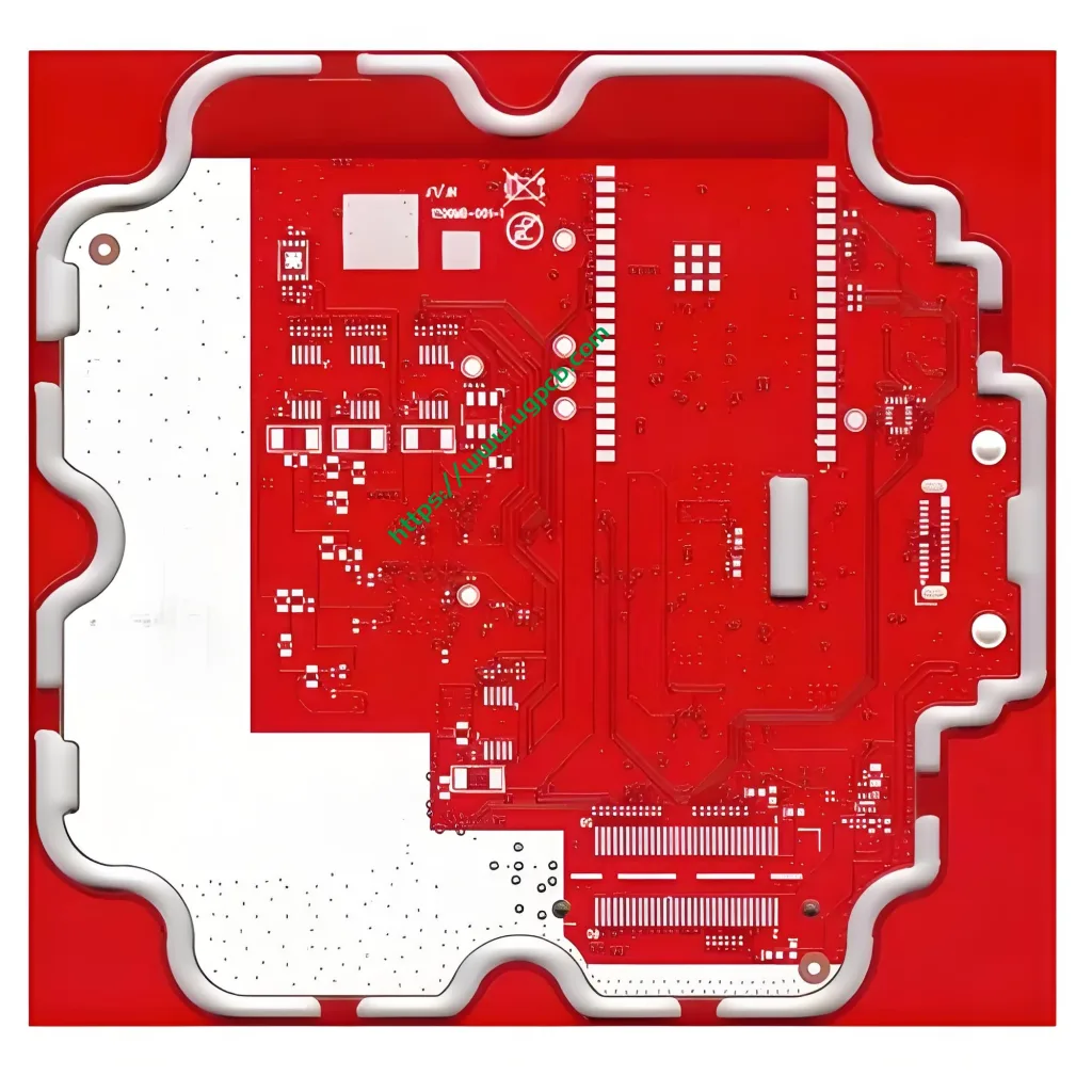
UGPCB follows industry-leading standards. We launch the UGPCB Rogers RO4835 77G mmWave Radar Board. This is a deeply optimized high-frequency ハイブリッド基板 for the 77GHz band. It ensures signal integrity and greatly reduces material costs.
製品の概要 | Key Parameters of 77G mmWave Radar PCB
UGPCB’s 77G mmWave radar PCB uses Rogers RO4835 high-frequency material and FR-4 hybrid solution. This 6-layer rigid 高周波プリント基板 is specially designed for mmWave radar antennas and RF front-ends.
Main technical parameters (data based on Rogers official datasheet and IPC standard test methods):
| パラメーター | 価値 | Test Standard / 注記 |
|---|---|---|
| Board Material | Rogers RO4835 (HF layer) + FR-4 (hybrid layer) | - |
| 誘電率 (DK) | 3.48 ± 0.05 @10GHz | IPC-TM-650 2.5.5.5 |
| 損失係数 (Df) | 0.0037 @10GHz | Rogers datasheet (corrected) |
| 誘電体の厚さ | 4ミル (0.1mm) | - |
| レイヤー数 | 6 レイヤー | - |
| Total Board Thickness | 1.2mm | - |
| 銅の厚さ | 1オンス (35μm) inner & outer | - |
| Via Process | Resin plugging | - |
| 表面仕上げ | 同意する (エレクトロレスニッケルイマージョンゴールド) | - |
| 熱伝導率 | 0.69 w/m・k | ASTM D5470 |
| 損失 (Df) | 0.0037 @10GHz | Consistent with above |
These parameters show very low dielectric loss and stable Dk tolerance. The hybrid high-frequency PCB fully meets 77GHz mmWave transmission requirements.
意味 | What Is a 77GHz mmWave Radar PCB?
A 77GHz mmWave radar PCB is a printed circuit board specially made for mmWave radar modules working at 77GHz. このタイプの プリント基板 must have low Dk, low Df, high dimensional stability, 優れた熱管理.
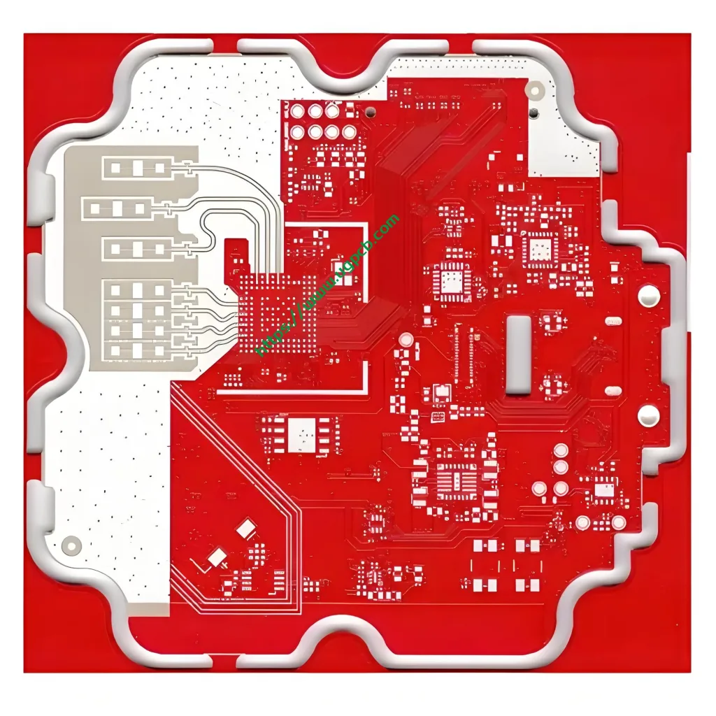
UGPCB’s Rogers RO4835 77G mmWave radar board uses RO4835 on the core RF layer. It uses cost-effective FR-4 on other layers. This creates a typical high-frequency hybrid PCB solution. The solution protects mmWave signal integrity and controls total cost well. It is an ideal choice for forward radar, corner radar, and 4D imaging radar.
設計のポイント | Core Considerations for mmWave Radar PCB
77GHz is a typical operating frequency in the mmWave band. At this frequency, PCB design must strictly follow high-frequency rules.
1. インピーダンス制御
The RF chain (アンテナ, transceiver, フィルター) on a 77GHz circuit uses a 50Ω characteristic impedance baseline. Engineers use impedance calculation tools like Polar SI9000. They precisely adjust line width, 誘電体の厚さ, および銅の厚さ. The goal is ±5% tolerance for single-ended 50Ω and differential 100Ω. For high-frequency microwave PCBs, the industry requires impedance control better than ±5% (that means 47.5–52.5Ω).
2. 材料の選択
Standard FR-4 has a Df of about 0.02. Rogers RO4835 has a Df of only 0.0037 (@10GHz). Signal transmission loss differs by more than 5 回. Wrong material choice directly reduces radar detection distance dramatically.
3. Stack-up Structure Design
In UGPCB’s 6-layer radar board, RF signal traces run inside the RO4835 dielectric between the top layer (L1) and L2. The other layers use FR-4 material. This ensures low-loss transmission on signal layers. その間, the FR-4 layers handle power distribution and signal filtering. This stack-up is called an asymmetric design for high-frequency hybrid PCBs.
4. ビアデザイン
77GHz signal vias need controlled impedance discontinuity. UGPCB uses resin plugging. We fill vias with resin and flatten the surface. This avoids signal reflection and loss caused by air gaps.
作業原則 | How Does a 77GHz Signal Transmit on the PCB?
On a PCB transmission line, high-frequency signal integrity depends on Dk and Df. The 77GHz mmWave radar board uses RO4835’s low Df property. High-frequency electromagnetic waves travel on microstrip or stripline with very little energy loss.
The antenna radiates radar waves into space. Then the receiving antenna sends echo signals back to the transceiver chip (such as NXP, Infineon, or TI 77GHz radar chipset). The hybrid FR-4 layer provides power and low-speed control signals. This keeps the whole module working stably in ADAS systems.
UGPCB PCBA capability further supports component assembly and testing. We offer true one-stop radar module manufacturing.
アプリケーション | Where to Use 77G mmWave Radar PCB
UGPCB’s 77G mmWave radar board fits many fields:
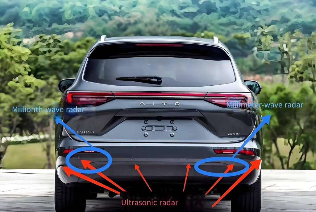
- Automotive forward radar – for adaptive cruise control (ACC) and automatic emergency braking (AEB)
- Corner radar – for blind spot detection (BSD) and lane change assist (LCA)
- 4D imaging radar – for elevation angle resolution and target classification
- Industrial mmWave radar – automation control, material level detection, security monitoring
- V2X and smart traffic – radar sensors in roadside units (RSU)
分類 | Scientific Categorization of 77G mmWave Radar PCB
According to industry standards and material systems, UGPCB’s Rogers RO4835 77G mmWave radar board has multiple classifications:
- By material system – RO4835 hydrocarbon resin + ceramic-filled high-frequency laminate (meets IPC-4103)
- By fabrication structure – High-frequency hybrid PCB (RF layer RO4835, ordinary layer FR-4)
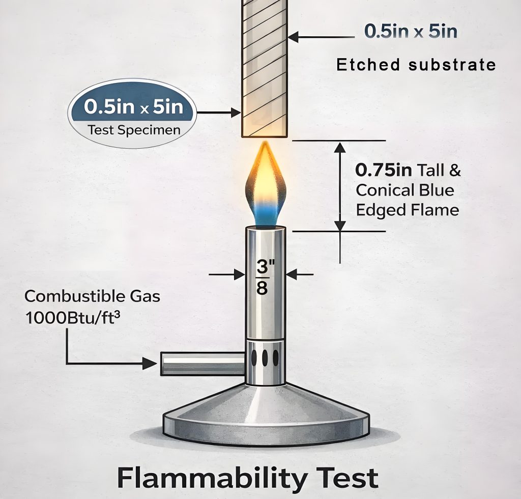
- By flame rating – UL 94 V-0 (self-extinguishes within 10 seconds after removing flame, no flaming drip ignites cotton)
- By PCB level – 6-layer rigid multilayer board
- By surface finish – ENIG (エレクトロレスニッケルイマージョンゴールド)
Reference note: RO4835 laminate meets IPC-4103 “Specification for High Frequency (電子レンジ) Base Materials” and satisfies UL 94 V-0 炎の評価. PCB 94V-0 means the material self-extinguishes within 10 seconds after removing the flame source, and no burning drip ignites cotton.
使用材料 | Scientific Combination of RO4835 and FR-4
UGPCB precisely selects two complementary materials for the radar board:
- Rogers RO4835 – a hydrocarbon resin and ceramic-filled microwave laminate. At 10GHz, Dk is 3.48±0.05 and Df is 0.0037. Oxidation resistance is 10 times better than traditional thermoset materials.
- FR-4 – a cost-effective flame-retardant epoxy woven glass fabric laminate, UL 94 V-0 定格. In the hybrid board, FR-4 handles power layers, ground layers, and low-frequency signal layers.
Because RO4835 and FR-4 have different coefficients of thermal expansion (CTE), lamination requires a step-wise heating profile and prepreg buffer layers. This prevents warpage and delamination.
パフォーマンス | 誘電, 損失, and Thermal Conductivity – Three in One
UGPCB’s Rogers RO4835 mmWave radar board excels in three key performance indicators:
| パラメーター | Value @10GHz | Test Standard / ソース |
|---|---|---|
| 誘電率 (DK) | 3.48 ± 0.05 | IPC-TM-650 2.5.5.5 |
| 損失係数 (Df) | 0.0037 | Rogers official datasheet |
| 熱伝導率 | 0.69 w/m・k | ASTM D5470 |
| Flame Rating | UL 94 V-0 | UL認定 |
| Oxidation improvement | 10x better than traditional thermoset | Rogers RO4835 datasheet |
This material has a Dk temperature coefficient of about 50 ppm/°C from -50°C to 150°C. Its Z-axis CTE is 31 ppm/°C. This means the 77G mmWave radar board keeps phase stability in the wide automotive temperature range.
構造 | Fine 6-Layer Hybrid Stack-up Design
UGPCB’s typical 6-layer high-frequency hybrid PCB stack-up:
| 層 | 銅 | 材料 | 関数 |
|---|---|---|---|
| L1 (トップ) | 1オンス | RO4835 | Signal – 77GHz RF traces (マイクロストリップ) |
| L2 | 1オンス | RO4835 | Ground – full RF reference ground |
| 誘電 | - | RO4835 (4mil/0.1mm) | Low-loss medium |
| L3 | 1オンス | RO4835/FR-4 transition | RF stripline / 配電 |
| L4-L6 | 1オンス | FR-4 | Conventional signal & パワーレイヤー |
This structure ensures RF signals travel between L1 and L2 using low-Dk, 低損失材料. The FR-4 part handles system logic and power integrity.
特徴 | Unique Advantages of 77G mmWave Radar PCB
- Oxidation stability – RO4835 offers 10 times better oxidation resistance than traditional thermoset materials. This greatly extends radar board life in harsh automotive environments.
- Low insertion loss design – Df=0.0037 ensures controllable attenuation for long-distance 77GHz signal transmission.
- Lead-free compatible – Fully RoHS compliant, supports lead-free reflow soldering.
- High PTH reliability – RO4835 provides high-quality plated through-hole reliability in multilayer boards, no blistering or delamination.
- Cost reduction with FR-4 hybrid – Hybrid design cuts total material cost by 30% に 60%, significantly improving project value.
- ENIG surface – Electroless nickel immersion gold ensures soldering reliability and gold wire bonding feasibility.
製造工程 | Precision from Material to Finished Board
UGPCB follows a strict high-frequency hybrid process for 77G mmWave radar boards:
- Material preparation – Clean and bake RO4835 high-frequency material and FR-4 substrates to keep low moisture absorption.
- Inner layer circuit – Use high-precision LDI exposure and fine etching for L1-L2 high-frequency signal layers. Line width control better than ±8μm.
- AOI検査 – Fully automatic optical inspection ensures no defects on inner layer patterns.
- ラミネート加工 – Use step-wise heating and pressure profile with prepreg buffer layers. This releases CTE mismatch stress and prevents delamination and warpage.
- 掘削 – Optimize drilling parameters separately for RO4835 and FR-4. Use low feed, 高速, plus plasma desmear.
- Resin plugging – Fill all vias with resin and flatten.
- Outer layer pattern and plating – Plate outer copper to 1oz, then etch final traces.
- ENIG表面仕上げ – Electroless nickel immersion gold, thickness meets IPC Class 2/3.
- Impedance test - 100% TDR test verifies 50Ω impedance ±5% accuracy on each board.
- Final inspection and electrical test – Flying probe test plus visual inspection ensure electrical performance.
使用シナリオ | Deploying UGPCB Radar Board in Real Systems
UGPCB’s 77G mmWave radar PCB can be directly deployed in these typical radar modules:
- Forward radar main board – Integrates Rogers RO4835 antenna layer with RF chip and MCU, supported by UGPCB’s one-stop PCBA assembly service.
- Corner radar antenna module – Hybrid RO4835+FR4 gives stable side detection at the lowest cost.
- 4D imaging radar – Multi-layer high-frequency hybrid stack-up supports multi-channel MIMO antenna arrays.
- Industrial radar sensor – Suitable for non-automotive high-frequency applications like smart warehouse AGVs and security radar.
UGPCBを選択する理由? – Get Your Quote Now
プロフェッショナルとして プリント基板の製造 and PCBA service provider, UGPCB offers unique guarantees:
- High-frequency hybrid experience – Dedicated production line for Rogers, PTFE and other high-frequency materials hybrid with FR-4 for volume production.
- 高精度 – Line width control within 10%, 100% TDR testing, impedance accuracy ±5%.
- Automotive-grade quality system – Meets IATF 16949 automotive certification requirements.
- Quick-turn service – Samples delivered in 7-10 days for fast iteration.
- One-stop PCBA – Full service from radar board production to component assembly and functional testing.
👉 For 77G mmWave radar PCB prototyping or mass production, contact us now. UGPCB’s technical team offers free DFM review and impedance design optimization advice. Send your Gerber files and technical requirements. We will provide the most competitive high-frequency hybrid PCB pricing and lead time.
Get your quote now → UGPCB Quick Inquiry Form
結論
で 2026, as autonomous driving and AI merge rapidly, the 77GHz mmWave radar becomes the core foundation of smart vehicle perception. UGPCB relies on Rogers RO4835’s low loss and high oxidation resistance. We combine it with FR-4’s flexible cost structure. The result is a high-frequency hybrid PCB solution that truly balances performance and mass production.
For the full datasheet or technical design support, please visit the UGPCB website. Our RF application engineers will assist you from layout design to radar board mass production.
Copyright Notice: All technical parameters in this document are sourced from the official Rogers datasheets and publicly available IPC industry standards. The data has been cross-verified by our senior engineers to guarantee accuracy. UGPCB reserves the right of final interpretation of this document.


