
Engineered for High-Frequency RF Performance: The UGPCB 2-Layer Halogen-Free Antenna PCB Solution
In the era of IoT and high-speed wireless communication, antenna performance is paramount to device connectivity and stability. UGPCB’s 2-Layer Halogen-Free Antenna PCB is a high-performance, environmentally conscious printed circuit board solution engineered specifically for RF circuit design. It is more than a signal carrier; it is a critical component for optimizing antenna efficiency, ensuring precise impedance matching, and enhancing overall device reliability. With deep expertise in high-frequency تصميم ثنائي الفينيل متعدد الكلور, we deliver a complete PCB to ثنائي الفينيل متعدد الكلور solution through stringent process controls and meticulous material selection.
In-Depth Analysis: From Materials to Structure
1. Product Definition
A 2-layer halogen-free antenna PCB is a double-sided circuit board dedicated to RF antenna circuitry. Its defining characteristic is the use of an environmentally friendly substrate free from halogens (chlorine, البروم). This makes it compliant with international directives like RoHS while meeting stringent RF performance requirements, making it particularly suitable for consumer electronics and export-oriented products.
2. Core Materials & Electrical Properties
-
Substrate Material: Premium Halogen-Free FR-4 laminate. This material emits very low levels of toxic gases when combusted, offering enhanced safety and environmental benefits.
-
ثابت العزل الكهربائي (DK): A stable Dk value of 4.2. This is a critical parameter for antenna ثنائي الفينيل متعدد الكلور design. A stable Dk ensures consistent signal propagation velocity, forming the foundation for predictable antenna impedance control and performance.
-
Copper Weight: Base copper of 0.5 أوقية, finished copper thickness of 1 أوقية (35ميكرومتر). The thickened copper layer helps reduce conductor loss and improves antenna radiation efficiency.
-
الانتهاء من السطح: الغمر الذهب (يوافق). Provides excellent solderability, superior oxidation resistance, and a flat surface for antenna contact points or solder pads, making it ideal for the ثنائي الفينيل متعدد الكلور and SMT assembly process.
3. Structural Design & Key Parameters
-
عدد الطبقة & سماكة: 2-layer construction with a standard finished board thickness of 0.8mm, ideal for wireless modules and compact devices.
-
Line Precision: Minimum trace/space capability of 12mil/12mil. We maintain strict tolerances to ensure precise routing control, which is essential for accurate 50Ω microstrip transmission line design. This directly impacts antenna performance metrics like return loss and VSWR.
-
Solder Mask Options: Standard green or white solder mask. White mask is especially beneficial for laser marking and high-end product identification.
Design Essentials & Operating Principle
Key Design Considerations:
-
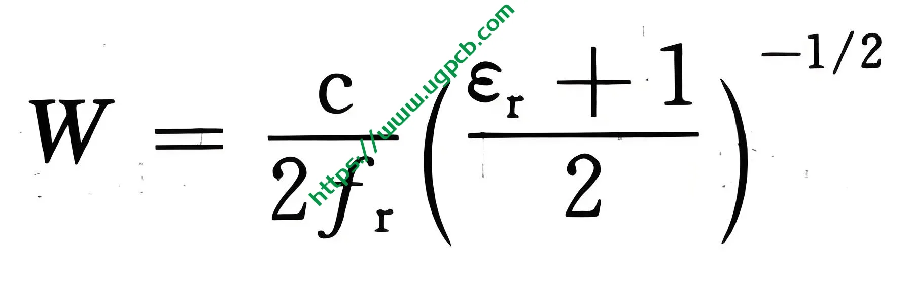
مطابقة المعاوقة: Utilizing the stable Dk (4.2) and precise trace width control (12ميل), designers can calculate or simulate exact 50Ω microstrip lines for perfect impedance matching between the antenna and the RF front-end.
-
Grounding Strategy: A well-planned ground plane (أرض) provides a complete return path for RF signals, minimizing interference and radiation loss.
-
Layout Isolation: Physically and spatially isolating the antenna section from other high-speed digital circuits (على سبيل المثال, MCU, DC-DC converters) to prevent noise coupling.
Operating Principle:
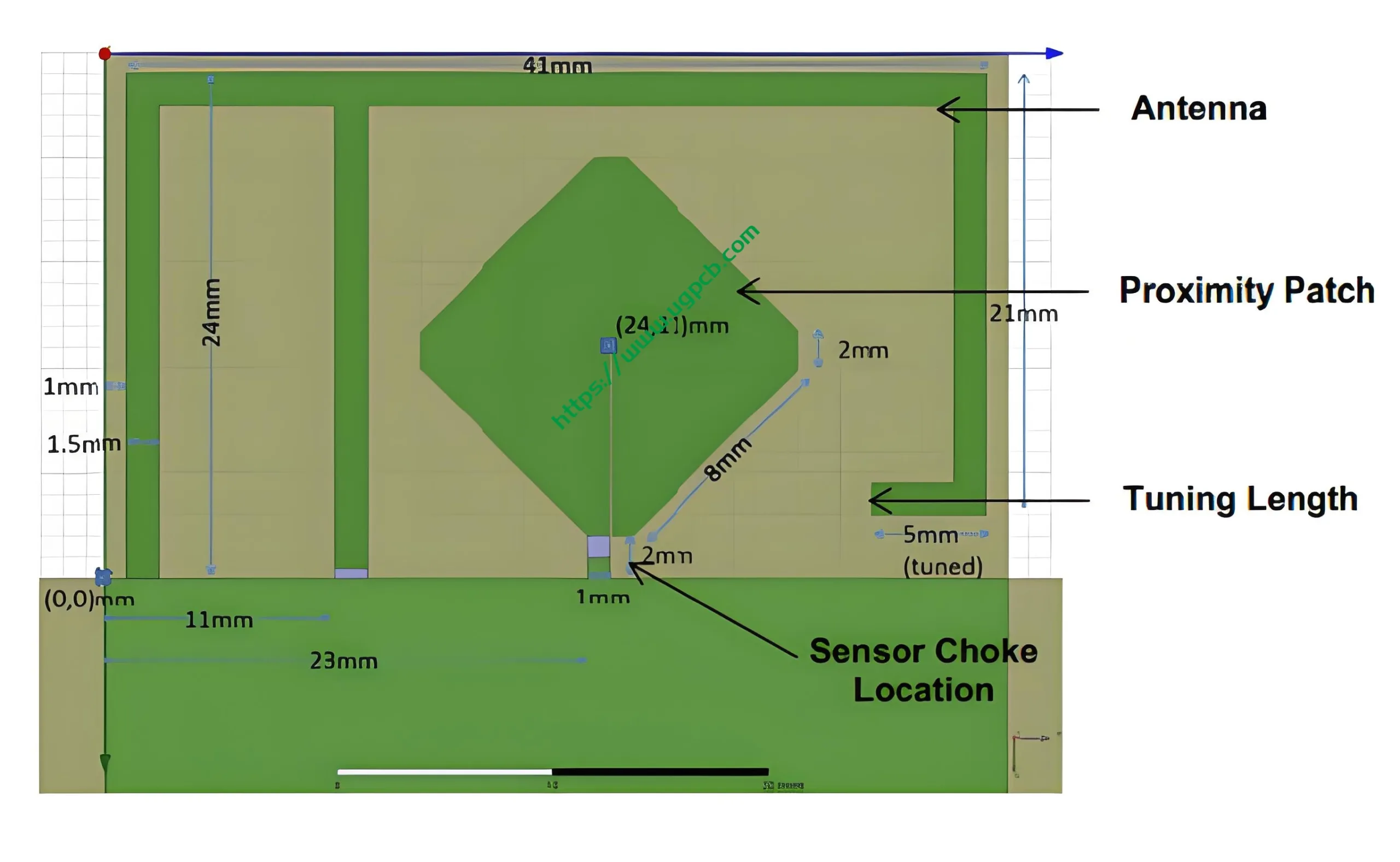
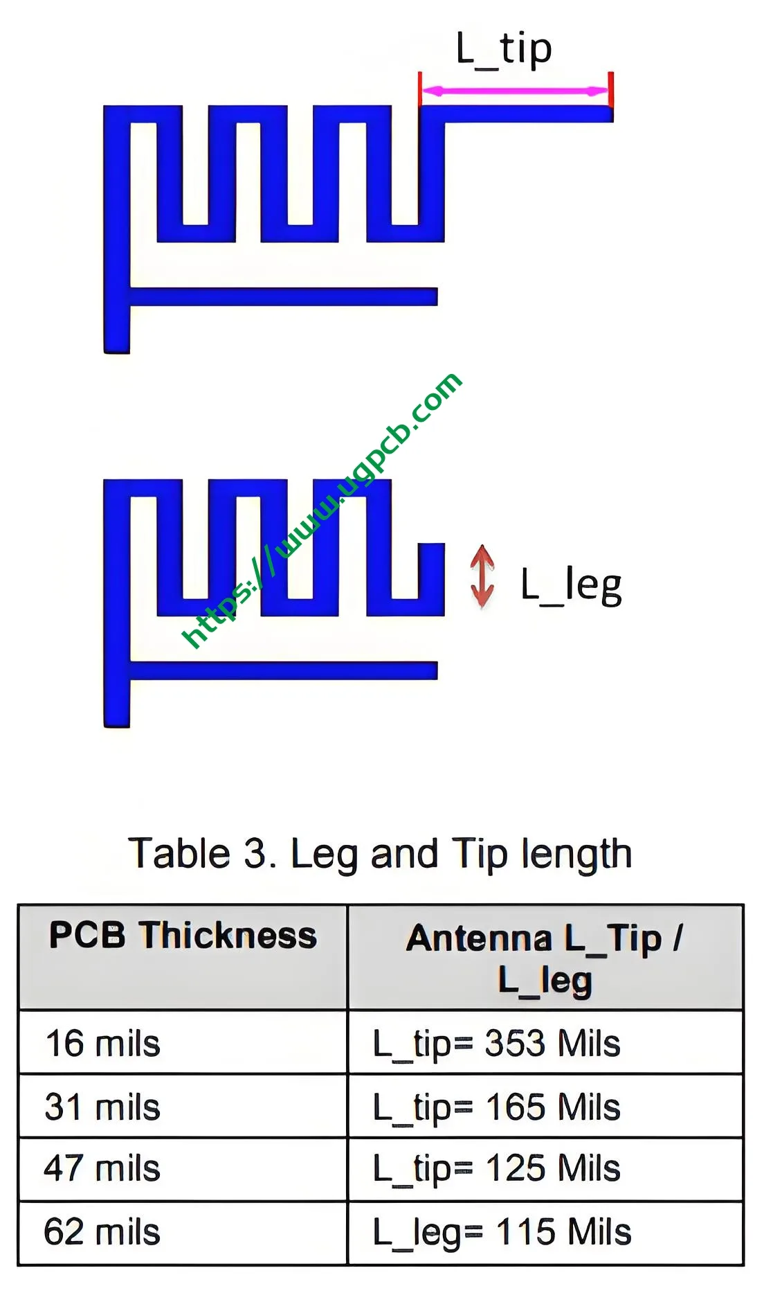
The copper traces on the antenna PCB are designed into specific geometries (على سبيل المثال, Inverted-F Antenna, meander line antenna). When an RF signal travels from the chip through a matching network to the antenna, these traces convert the electrical signal into electromagnetic waves for radiation (transmit mode) or convert incoming electromagnetic waves into electrical signals (receive mode). The efficiency of this process is highly dependent on the dielectric stability of the PCB laminate and the precision of the trace fabrication.
سمات & Advantages
-
Stable High-Frequency RF Performance: Consistent Dk (4.2) and strict trace tolerances ensure reliable, repeatable antenna performance across production batches.
-
Eco-Friendly & موثوق: Halogen-free materials meet green manufacturing standards, enhancing product safety and market accessibility.
-
High-Process Quality: ENIG surface finish offers oxidation resistance and long shelf life, providing perfect pads for subsequent SMT assembly and PCBA العمليات.
-
Expert Design Support: UGPCB offers PCB design review services to help customers optimize antenna layout and stack-up, avoiding common RF design pitfalls.
-
Image Suggestion 2: Microscope image comparing precise 12mil trace/space edges.
-
Image Alt Text: Close-up of high-precision 12mil trace/space on PCB, critical for consistent antenna impedance.
عملية الإنتاج & ضمان الجودة
UGPCB’s production workflow strictly adheres to the special requirements for high-frequency تصنيع ثنائي الفينيل متعدد الكلور:
Engineering Review → Halogen-Free Material Cutting → Laser Drilling → Deposition & Plating → Precision Pattern Transfer → Acid Etching (Strict Line Width Control) → ENIG Surface Finish → Solder Mask Application → Electrical & Flying Probe Testing → Final Inspection & التعبئة والتغليف.
We implement enhanced controls, particularly during pattern transfer and etching, to achieve stringent trace tolerance requirements. Stability of the Dk value is verified through periodic sampling with network analyzers.
Wide Range of Applications
This 2-layer halogen-free antenna PCB serves as the “heart” of numerous wireless communication devices. Typical applications include:
-
IoT Devices: Smart home sensors, Bluetooth modules, LoRa modules.
-
Network Communications: Wi-Fi routers, نقاط الوصول اللاسلكية, network cameras.
-
الالكترونيات الاستهلاكية: Wireless headphones, remote controls, wearable technology.
-
السيطرة الصناعية: Wireless data collectors, remote monitoring terminals.

Whether you require rapid prototype تصنيع ثنائي الفينيل متعدد الكلور or large-scale volume production, UGPCB provides reliable, فعال antenna PCB manufacturing and comprehensive PCBA assembly services to accelerate your product’s time-to-market.
-
Image Suggestion 3: Collage of application scenarios (PCB integrated into end-products like smart home devices, routers, الأجهزة القابلة للارتداء).
-
Image Alt Text: Application of 2-layer halogen-free antenna PCB in Wi-Fi routers, IoT sensors, and wireless devices.
Contact us today to get your customized 2-Layer Halogen-Free Antenna PCB solution and quote! Let UGPCB’s expertise become the solid foundation for your wireless product’s success.


