


أنا. نظرة عامة على المنتج
إن لوحة PCB ذات الفتحة المزدوجة من UGPCB هي عبارة عن طبقة صلبة عالية الأداء مكونة من طبقتين لوحة الدوائر المطبوعة مبني على ركيزة من الإيبوكسي الزجاجي FR-4 باستخدام فتحة مطلية (PTH) تكنولوجيا. تدابير المجلس 86.9 × 73.58 ملم بسمك 1.0 مم, سمك رقائق النحاس 1/1 أوقية (35 ميكرومتر على كل من الطبقات الخارجية والداخلية), وتسوية لحام بالهواء الساخن خالية من الرصاص (ينزف) الانتهاء من السطح. قناع اللحام أخضر, والأسطورة بالشاشة الحريرية بيضاء.
ثنائي الفينيل متعدد الكلور من خلال ثقب على الوجهين (لوحة دوائر مطبوعة على الوجهين) يتميز بدوائر موصلة على جانبي الركيزة العازلة, مع فتحات مطلية تتيح التوصيل الكهربائي بين الطبقتين. بالمقارنة مع ثنائي الفينيل متعدد الكلور أحادي الجانب, توفر مركبات ثنائي الفينيل متعدد الكلور ذات الوجهين كثافة توجيه أعلى بنسبة 60% إلى 80% وتدعم تصميمات الدوائر الأكثر تعقيدًا. UGPCB, مدعومة بأنظمة الجودة المعتمدة من ISO وعمليات التصنيع المتوافقة مع IPC, توفر مركبات ثنائي الفينيل متعدد الكلور عالية الجودة على الوجهين من خلال الفتحات والتسليم على المفتاح ثنائي الفينيل متعدد الكلور خدمات لمصنعي الإلكترونيات في جميع أنحاء العالم.
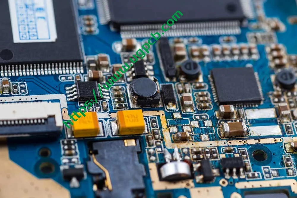
ثانيا. تعريف المنتج والمواصفات الفنية
لكل IPC-6012F مواصفات التأهيل والأداء للألواح المطبوعة الصلبة (نشرت سبتمبر 2023), يتم تصنيف ثنائي الفينيل متعدد الكلور ذو الفتحة المزدوجة على أنه لوحة مطبوعة صلبة ذات فتحات مطلية (يكتب 2). وتتمثل الميزة الأساسية لها في التوصيل الكهربائي بين الموصلات على كلا الجانبين من خلال جدران الفتحات المطلية بالنحاس. تقوم UGPCB بتصنيع هذا المنتج بما يتوافق تمامًا مع IPC-6012F ويتوافق مع الفئة 2 متطلبات الأداء (معدات إلكترونية مخصصة للخدمة).
المواصفات الرئيسية:
| المعلمة | مواصفة |
|---|---|
| مادة الركيزة | فر-4 (مثبطات اللهب UL 94 V-0) |
| عدد الطبقات | 2 طبقات (على الوجهين) |
| سمك المجلس | 1.0 مم |
| أبعاد اللوحة | 86.9 × 73.58 مم |
| الحد الأدنى قطر الثقب | 0.236 مم |
| الحد الأدنى لعرض الخط / تباعد | 0.32 × 0.37 مم |
| سمك رقائق النحاس | 1/1 أوقية (تقريبا. 35 ميكرومتر من كل جانب) |
| الانتهاء من السطح | HASL خالي من الرصاص (تسوية لحام الهواء الساخن) |
| قناع اللحام / أسطورة | قناع اللحام الأخضر / بالشاشة الحريرية البيضاء |
ثالثا. إرشادات التصميم
3.1 اختيار مادة الركيزة — القيمة الهندسية لـ FR-4
فر-4 is a flame-retardant grade designation established by the National Electrical Manufacturers Association (NEMA). The letters “الاب” stand for flame-retardant, and the number “4” denotes an epoxy resin system reinforced with woven glass fabric. لIPC-4101 مواصفات المواد الأساسية للوحات المطبوعة الصلبة ومتعددة الطبقات, FR-4 Grade A1 represents the core performance tier with optimal mechanical strength, electrical properties, and long-term reliability.
Key Performance Indicators of FR-4 (مصدر: IPC-4101 and industry standards):
-
درجة حرارة انتقال الزجاج (تيراغرام): 130-140 درجة مئوية (معيار FR-4)
-
ثابت العزل الكهربائي (DK) @ 1 GHz: 4.2–4.5
-
عامل التبديد (ص) @ 1 GHz: ≥ 0.020
-
تصنيف القابلية للاشتعال: أول 94 V-0
-
امتصاص الماء (24 ساعات): ≥ 0.10%
FR-4 remains the predominant substrate material in the PCB industry because it offers an outstanding balance of mechanical strength, العزل الكهربائي, استقرار الأبعاد, and processability.
3.2 Circuit Design Standards per IPC-2221
لIPC-2221 المعيار العام لتصميم اللوحة المطبوعة, conductor width design must account for current-carrying capacity, ارتفاع درجة الحرارة, وسمك النحاس. صيغة القدرة الاستيعابية الحالية IPC-2221 هي:
أنا = ك · ΔT^0.44 · أ^0.725
أين:
-
I = الحد الأقصى لقدرة الحمل الحالية (أ)
-
ك = ثابت تجريبي (0.048 للطبقات الخارجية, 0.024 للطبقات الداخلية)
-
ΔT = ارتفاع درجة الحرارة المسموح به (درجة مئوية)
-
A = مساحة المقطع العرضي للموصل (ميل²), حيث أ = ث × ت
يتميز منتج UGPCB بعرض خط يبلغ 0.32 مم (تقريبا. 12.6 ميل), تباعد الأسطر من 0.37 مم (تقريبا. 14.6 ميل), وسمك النحاس 1 أوقية (35 ميكرومتر). لتتبع الطبقة الخارجية مع ارتفاع درجة الحرارة 10 درجات مئوية:
أ = 0.32 مم × 0.035 مم = 0.0112 مم² ≈ 17.36 ميل²
أنا = 0.048 × 10^0.44 × 17.36^0.725 ≈ 0.048 × 2.75 × 7.82 ≈ 1.03 أ
يدعم عرض الموصل هذا تقريبًا 1 أ من الحالي, تلبية احتياجات نقل الطاقة والإشارات لمعظم الأجهزة الإلكترونية الاستهلاكية ومعدات التحكم الصناعية. يوصي IPC-2221 بتحديد الحد الأقصى لارتفاع درجة الحرارة إلى 10 درجات مئوية أو 20 درجة مئوية للحفاظ على عمر خدمة ثنائي الفينيل متعدد الكلور.
3.3 قطر الثقب وتصميم نسبة الارتفاع
تعد نسبة العرض إلى الارتفاع للفتحة مقياسًا مهمًا لتقييم صعوبة الحفر وصعوبة تعدين الثقب. الصيغة هي:
نسبة الارتفاع = سمك اللوحة / قطر الثقب المحفور
بالنسبة لمنتج UGPCB مع 1.0 سمك اللوح مم و 0.236 مم الحد الأدنى لقطر الثقب:
نسبة الارتفاع = 1.0 / 0.236 ≈ 4.24:1
نسبة العرض إلى الارتفاع هذه أقل بكثير من الحد الأعلى الموصى به في الصناعة وهو 10:1 وعتبة التصميم المحافظ ل 8:1. يشير إلى صعوبة منخفضة في الحفر والتعدين, معدلات عائد عالية, التكاليف الخاضعة للرقابة, وموثوقية مضمونة من خلال الحفرة.
3.4 مرجع تصميم نمط الأرض
لIPC-7351 المتطلبات العامة لتصميم التركيب على السطح ومعيار نمط الأرض, يجب أن يضمن تصميم نمط الأرض تكوينًا مناسبًا لشرائح اللحام ويلبي قابلية اللحام, قابلية الفحص, ومتطلبات إعادة العمل. للمكونات من خلال ثقب, يوصى عادةً بقطر الأرض بمقدار 1.8-2.2 ضعف قطر الثقب لضمان عرض الحلقة الحلقية الكافية.
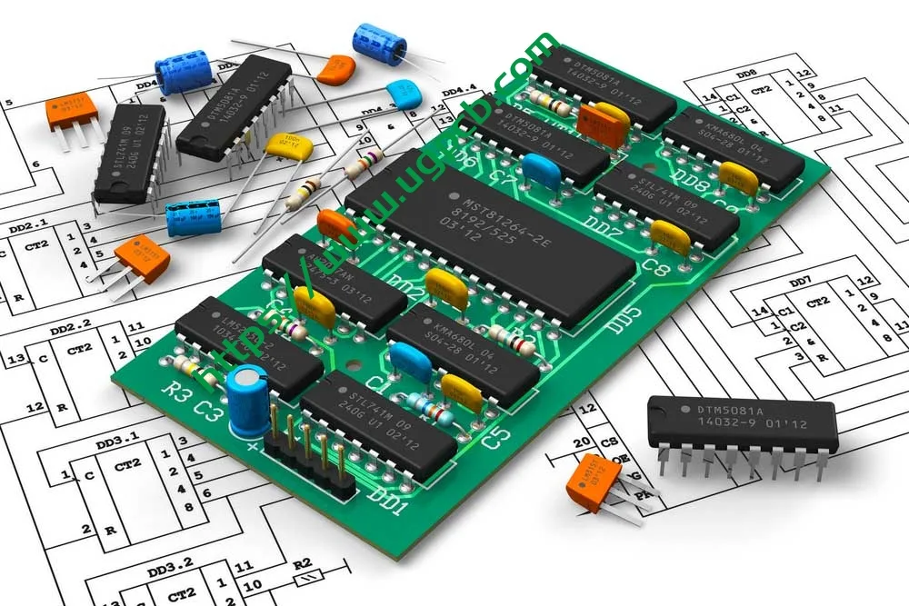
رابعا. مبدأ التشغيل
يعمل ثنائي الفينيل متعدد الكلور ذو الفتحة المزدوجة على ثلاث تقنيات أساسية:
1. التوجيه على الوجهين - يتم حفر أنماط الدوائر الموصلة على كل من الأسطح العلوية والسفلية للركيزة العازلة FR-4, السماح بوضع المكونات على كلا الجانبين. وهذا يزيد بشكل كبير من كثافة الدائرة ومرونة التصميم.
2. مطلي من خلال هول (PTH) الربط - بعد الحفر, يعمل ترسيب النحاس اللاكهربائي وطلاء النحاس الإلكتروليتي على بناء طبقة موصلة على جدران الثقب. وهذا يخلق مقاومة منخفضة, توصيلات كهربائية موثوقة للغاية بين الطبقات العلوية والسفلية. لكل فئة IPC-6012F 2, يجب أن يكون الحد الأدنى لمتوسط سمك النحاس المطلي على جدران الفتحات ≥ 20 ميكرومتر.
3. تجميع المكونات واللحام - يتم تركيب المكونات من خلال الفتحة (تي إتش تي) أو جبل السطح (سمت) تقنيات ومتصلة كهربائيا عن طريق إنحسر أو لحام الموجة, إنتاج PCBA تعمل بكامل طاقتها (مجموعة لوحة الدوائر المطبوعة) الوحدة النمطية.
V. تصنيف المنتج
وفقًا لنظام التصنيف IPC-6012F للألواح المطبوعة الصلبة, يتم تصنيف منتج UGPCB على النحو التالي:
| البعد التصنيفي | فئة |
|---|---|
| بواسطة البناء | لوح مطبوع صلب مزود بفتحات مطلية, على الوجهين (نوع IPC-6012F 2) |
| حسب فئة الأداء | فصل 2 (المعدات الإلكترونية المخصصة للخدمة) |
| بواسطة مادة الركيزة | FR-4 صفح نسيج زجاجي إيبوكسي (IPC-4101/21) |
| حسب عدد الطبقات | 2-لوحة الطبقة |
| بواسطة الانتهاء من السطح | HASL خالي من الرصاص |
| حسب تصنيف القابلية للاشتعال | أول 94 V-0 |
حسب مجال التطبيق, يقع هذا المنتج في ثنائي الفينيل متعدد الكلور ذو الوجهين من الدرجة الصناعية العامة فئة, مناسبة للإلكترونيات الاستهلاكية, الضوابط الصناعية, معدات الاتصالات, محولات الطاقة, وغيرها من التطبيقات متوسطة الموثوقية.
سادسا. تكوين المواد
6.1 الركيزة - صفائح نحاسية FR-4
FR-4 عبارة عن صفائح إيبوكسي مقواة بالزجاج تتكون من نسيج زجاجي منسوج من الدرجة الإلكترونية كتعزيز وراتنجات الإيبوكسي كمواد رابطة, موحدة تحت درجة حرارة عالية والضغط. لها ماي 94 V-0 تصنيف القابلية للاشتعال يعني ذلك في اختبار الحرق العمودي, تنطفئ المادة ذاتيًا بداخلها 10 ثوانٍ بعد كل تطبيق من تطبيقي اللهب لمدة 10 ثوانٍ, مع عدم وجود قطرات مشتعلة تشعل القطن.
6.2 رقائق النحاس — 1/1 أوقية
أونصة واحدة (1 أوقية) من رقائق النحاس يبلغ سمكها 35 ميكرومتر (1.37 ميل). يستخدم UGPCB 1 OZ النحاس على كلا الطبقتين الخارجيتين (معين 1/1 أوقية), ضمان القدرة على حمل التيار والموصلية على كلا الجانبين.
6.3 تشطيب السطح - HASL خالي من الرصاص
يتضمن HASL الخالي من الرصاص غمر ثنائي الفينيل متعدد الكلور في لحام خالي من الرصاص المنصهر (عادة Sn-Cu, سن-كو-ني, أو سبائك Sn-Ag-Cu), ثم استخدم سكاكين الهواء الساخن ذات الضغط العالي لتسوية وإزالة اللحام الزائد. هذا ينتج زيا موحدا, طلاء وقائي قابل للحام على الأسطح النحاسية. تتوافق العملية مع متطلبات IPC-6012F والتوجيهات البيئية لـ RoHS.
6.4 قناع اللحام والأسطورة
-
قناع اللحام الأخضر - يغطي جميع مناطق الدائرة باستثناء الوسادات, توفير العزل, حماية الأكسدة, ومنع ماس كهربائى.
-
أسطورة الشاشة الحريرية البيضاء - يحدد المسميات المرجعية للمكونات, علامات القطبية, أرقام أجزاء اللوحة, ومستويات المراجعة لتسهيل التجميع والتصحيح.
سابعا. أداء المنتج
7.1 الأداء الكهربائي
| معلمة الأداء | قيمة | المعيار المرجعي |
|---|---|---|
| ثابت العزل الكهربائي (DK) @ 1 GHz | 4.2–4.5 | إيبك-4101 |
| عامل التبديد (ص) @ 1 GHz | ≥ 0.020 | إيبك-4101 |
| مقاومة العزل | ≥ 10^12 أوم | IPC-6012F |
| عازلة تحمل الجهد | لكل قوة عازلة | IPC-6012F |
7.2 الأداء الميكانيكي
| معلمة الأداء | قيمة | المعيار المرجعي |
|---|---|---|
| سمك المجلس | 1.0 مم ± 10% | IPC-6012F |
| قوة قشر النحاس | ≥ 1.1 ن / مم | IPC-6012F |
| تصنيف القابلية للاشتعال | أول 94 V-0 | معيار UL |
| تيراغرام (درجة حرارة انتقال الزجاج) | 130-140 درجة مئوية | إيبك-4101 |
7.3 مصداقية
لكل فئة IPC-6012F 2 متطلبات, يجب أن يجتاز المنتج عمليات التحقق من الموثوقية التالية:
-
اختبار الإجهاد الحراري (288درجة مئوية, 10 ثواني, لا التصفيح أو تقرحات)
-
اختبار التصاق النحاس المطلي من خلال الفتحة (الحد الأدنى لمتوسط سمك النحاس في جدار الثقب ≥ 20 ميكرومتر)
-
اختبار قابلية اللحام
-
اختبار الاستمرارية الكهربائية ومقاومة العزل
ثامنا. هيكل المنتج
يتميز ثنائي الفينيل متعدد الكلور ذو الفتحة المزدوجة من UGPCB ببنية متماثلة من طبقتين. من الأعلى إلى الأسفل:
-
أعلى طبقة أسطورة (بالشاشة الحريرية البيضاء)
-
طبقة قناع اللحام العلوي (الحبر الأخضر)
-
طبقة رقائق النحاس العلوية (1 أوقية, 35 ميكرومتر)
-
الركيزة العازلة FR-4 (1.0 سمك مم)
-
طبقة رقائق النحاس السفلية (1 أوقية, 35 ميكرومتر)
-
طبقة قناع اللحام السفلي (الحبر الأخضر)
-
طبقة الأسطورة السفلية (بالشاشة الحريرية البيضاء)
-
مطلي من خلال الثقوب (PTH) - قم بتمديد سمك اللوحة بالكامل بجدران مثقوبة مطلية بالنحاس مما يتيح التوصيل البيني للطبقات
تاسعا. ميزات المنتج
-
كثافة توجيه عالية — يوفر التوجيه مزدوج الجوانب كثافة أعلى بنسبة 60% إلى 80% من اللوحات أحادية الجانب, دعم تصاميم الدوائر الأكثر تعقيدا.
-
اتصال بيني موثوق به للغاية عبر الفتحات - مطلي من خلال الفتحة (PTH) تضمن التكنولوجيا الموثوقية الكهربائية على المدى الطويل بين الطبقات, مع سمك النحاس ذو الجدار المثقوب الذي يتوافق مع فئة IPC-6012F 2 متطلبات (≥ 20 ميكرومتر متوسط).
-
تثبيط اللهب ممتاز - الركيزة FR-4 تلبي معايير UL 94 V-0 تصنيف القابلية للاشتعال, ضمان السلامة في ظل ظروف التشغيل غير الطبيعية.
-
خالية من الرصاص وصديقة للبيئة — يتوافق تشطيب سطح HASL الخالي من الرصاص مع التوجيهات البيئية لـ RoHS.
-
قدرة الدائرة الدقيقة - الحد الأدنى لعرض الخط 0.32 مم والحد الأدنى للتباعد 0.37 مم استيعاب المتوسطة- لتصميم الدوائر عالية الكثافة.
-
استقرار الأبعاد متفوقة - امتصاص الماء المنخفض لـ FR-4 (≥ 0.10%) يضمن الحد الأدنى من تغيير الأبعاد في البيئات الرطبة, الحفاظ على دقة التجميع.
-
عملية التصنيع الناضجة - مع 1.0 سمك اللوح مم و 0.236 مم الحد الأدنى لقطر الثقب, نسبة العرض إلى الارتفاع فقط 4.24:1 تمكن العمليات الناضجة, عوائد عالية, ومهل زمنية قصيرة.
X. تدفق عملية التصنيع
عملية تصنيع ثنائي الفينيل متعدد الكلور القياسية على الوجهين من خلال الفتحات الخاصة بشركة UGPCB:
1. فحص المواد الواردة → تحقق من سمك الصفائح المغطاة بالنحاس FR-4, نوعية رقائق النحاس, والعيوب البصرية.
2. قطع → قطع صفائح نحاسية كبيرة الحجم لتناسب حجم لوحة العمل (86.9 × 73.58 مم).
3. حفر → استخدم آلات الحفر CNC عالية الدقة لحفر جميع الثقوب في ملف حفر جربر (الحد الأدنى للقطر 0.236 مم).
4. مطلي من خلال هول (PTH) ← قم بإيداع طبقة رقيقة من بذور النحاس على جدران الثقب عن طريق ترسيب النحاس اللاكهربائي.
5. طلاء اللوحة → لوحة النحاس كهربائيا لبناء جدار الثقب والنحاس السطحي لاستهداف السُمك (1 أوقية).
6. نقل النمط → صفح الفيلم الجاف, يفضح, وتطويرها لتشكيل نمط الدائرة المقاومة.
7. النقش ← قم بحفر النحاس غير المحمي لتشكيل نمط الدائرة النهائي.
8. تجريد → قم بإزالة طبقة مقاومة الجفاف من آثار الدائرة.
9. تطبيق قناع اللحام → تطبيق حبر قناع اللحام الأخضر, يفضح, وتطوير لفضح منصات.
10. الانتهاء من السطح → HASL خالية من الرصاص.
11. طباعة الأسطورة → أسطورة الشاشة الحريرية البيضاء المطبوعة بالشاشة الحريرية.
12. التوجيه / قطع على شكل حرف V → توجيه CNC إلى المخطط النهائي للوحة.
13. الاختبار الكهربائي → اختبار المسبار الطائر أو التركيبات للتحقق من السلامة المفتوحة/القصيرة.
14. مراقبة الجودة النهائية (FQC) → الفحص البصري, أخذ العينات الأبعاد, والتعبئة والتغليف للشحن.
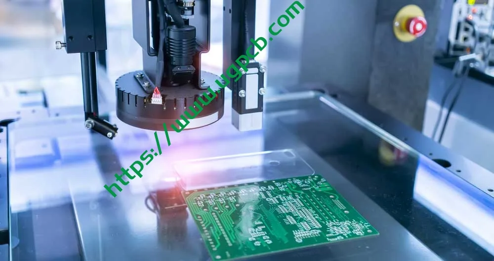
الحادي عشر. سيناريوهات التطبيق
لوحات UGPCB مزدوجة الجوانب من خلال الفتحات FR-4 PCB, مع أدائها المتوازن والعمليات الناضجة, تستخدم على نطاق واسع في:
11.1 الالكترونيات الاستهلاكية
-
محولات الطاقة وأجهزة الشحن
-
لوحات تحكم الأجهزة المنزلية
-
الأجهزة المنزلية الذكية
11.2 الضوابط الصناعية
-
وحدات التحكم المنطقية القابلة للبرمجة PLC
-
وحدات الطاقة الصناعية
-
الأجهزة والعدادات
11.3 معدات الاتصالات
-
أجهزة التوجيه والمحولات
-
وحدات الاتصالات
-
أجهزة تحويل الإشارة
11.4 إلكترونيات السيارات
-
أجهزة الشحن على متن الطائرة
-
وحدات التحكم في الجسم (غير السلامة الحرجة)
-
أنظمة المعلومات والترفيه
11.5 الأجهزة الطبية
-
لوحات مساعدة لمراقبة المريض
-
المعدات الطبية المحمولة (فصل 2 ملائم)
الثاني عشر. مزايا المنتج ودليل الاختيار
12.1 لماذا تختار UGPCB ثنائي الفينيل متعدد الكلور ذو الفتحة المزدوجة?
-
التحكم في العمليات المتوافقة مع IPC - من اختيار المواد إلى السلع التامة الصنع, الامتثال الكامل لـ IPC-6012F, إيبك-4101, وغيرها من المعايير الدولية.
-
تصنيع عالي الدقة - الحد الأدنى لقطر الثقب 0.236 ملم والحد الأدنى لعرض الخط 0.32 مم تلبية المتوسطة- لمتطلبات التصميم عالية الكثافة.
-
الامتثال البيئي — تشطيب سطح HASL الخالي من الرصاص يتوافق مع RoHS 2.0 التوجيهات.
-
موثوقية مثبتة — لقد تم اعتماد الركيزة FR-4 في السوق لعقود من الزمن مع أداء ثابت.
-
تسليم سريع — المواصفات القياسية مخزنة بمواد خام وافرة, ضمان فترات زمنية موثوقة.
12.2 مرجع الاختيار
تعد مركبات ثنائي الفينيل متعدد الكلور ذات الفتحات المزدوجة من UGPCB الخيار الأمثل عندما يفي مشروعك بهذه المعايير:
-
تعقيد الدائرة المعتدلة 2 يمكن أن تستوعب الطبقات
-
تردد التشغيل أدناه 1 GHz (يعمل FR-4 بشكل ممتاز في هذا النطاق)
-
بيئة تشغيل طويلة الأمد لا تتجاوز 120 درجة مئوية
-
التطبيقات الحساسة للتكلفة والتي تتطلب قيمة عالية
الثالث عشر. طلب عرض أسعار
تلتزم UGPCB بتقديم خدمات تصنيع PCBA عالية الجودة وخدمات PCBA الجاهزة للعملاء في جميع أنحاء العالم. سواء كنت بحاجة إلى مركبات ثنائي الفينيل متعدد الكلور ذات فتحة مزدوجة ذات مواصفات قياسية أو متطلبات مخصصة (سمك اللوحة الخاصة, وزن النحاس, الانتهاء من السطح, التحكم في المعاوقة, إلخ.), يقدم فريق الخبراء التابع لـ UGPCB الدعم الكامل بدءًا من التصميم الهندسي وحتى الإنتاج بكميات كبيرة.
احصل على عرض أسعار اليوم:
-
إرسال ملفات جربر + المواصفات - احصل على عرض أسعار داخل 24 ساعات
-
الدعم من النموذج الأولي إلى الإنتاج بكميات كبيرة
-
تصميم مجاني للتصنيع (سوق دبي المالي) مراجعة
اتصل بـ UGPCB:
📧 استفسارات المبيعات: [sales@ugpcb.com]
🌐 موقع الكتروني: [www.ugpcb.com]
الرابع عشر. إعلان مصدر البيانات
يتم الحصول على المعايير والبيانات المذكورة في هذه الوثيقة من المنظمات الرسمية التالية:
-
IPC (جمعية ربط الصناعات الإلكترونية): IPC-6012F مواصفات التأهيل والأداء للألواح المطبوعة الصلبة (سبتمبر 2023); إيبك-4101 مواصفات المواد الأساسية للوحات المطبوعة الصلبة ومتعددة الطبقات; IPC-2221 المعيار العام لتصميم اللوحة المطبوعة; IPC-7351 المتطلبات العامة لتصميم التركيب على السطح ومعيار نمط الأرض
-
أول (مختبرات الضامنين): أول 94 معيار اختبارات القابلية للاشتعال للمواد البلاستيكية لأجزاء الأجهزة والأجهزة
-
NEMA (الرابطة الوطنية لمصنعي الأجهزة الكهربائية): تعريف درجة المواد FR-4
-
البيانات الفنية القياسية الصناعية: ثابت العزل الكهربائي FR-4, عامل التبديد, وغيرها من معلمات خصائص المواد













