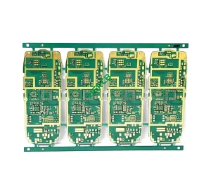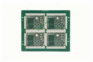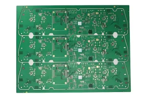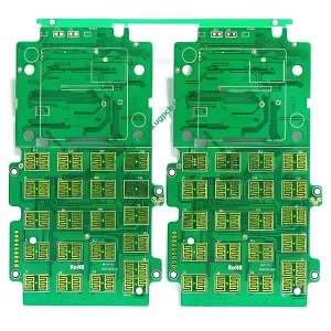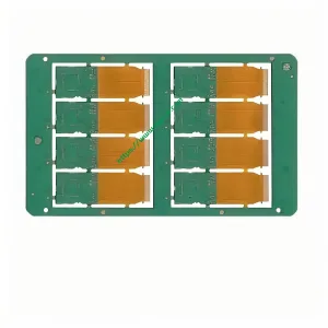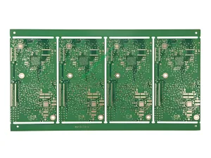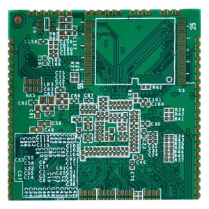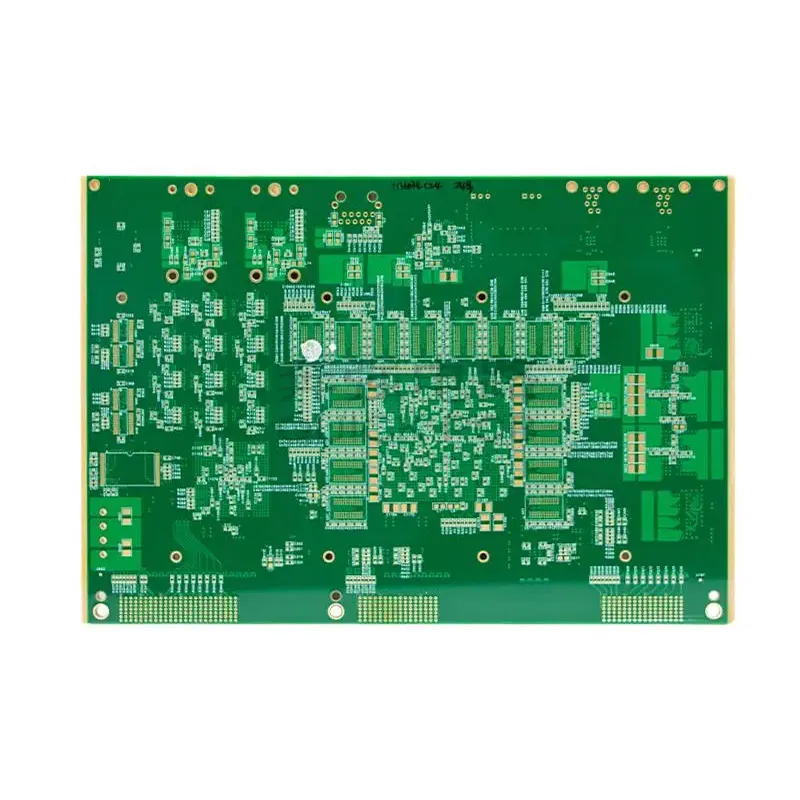
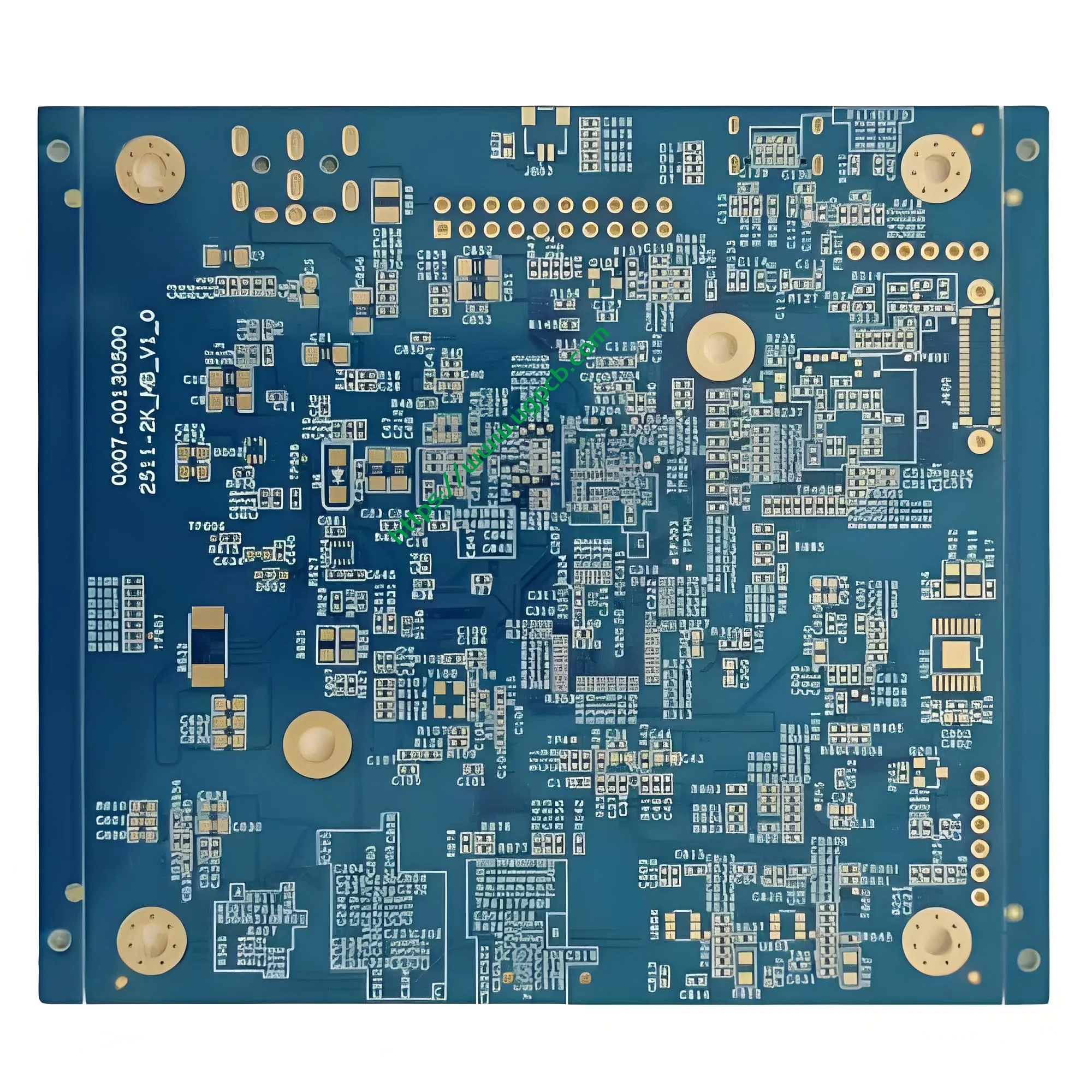


Product positioning: UGPCB’s 6-layer 1-stage HDI PCB uses a 1+N+1 stack-up. それは提供します 0.10 mm laser blind vias, 0.20 mm through holes, 0.20 mm BGA pitch, そして 3/3 mil traces. It suits compact, high-integration electronics.
1. What Is a 6-Layer 1-Stage HDI PCB?
A 6-layer 1-stage HDI PCB is a six-layer 高密度相互接続プリント基板. It uses a 1+N+1 stack-up, where N equals 4. IPC-2226 classifies this build-up approach as a Type I HDI 構造. Each side has one build-up layer. Laser microvias connect the outer layers to the next inner layer. Mechanical through holes connect the core layers.

Parameter Snapshot
| パラメーター | 仕様 |
|---|---|
| レイヤー数 | 6 レイヤー (1+n+1) |
| 基材 | FR4 TG150 |
| 板厚 | 1.6 mm |
| パネルサイズ | 105 × 95 mm (1-上) |
| 外側の銅の厚さ | 35 μm (1 オンス) |
| 内側の銅の厚さ | 30 μm |
| 最小スルーホール | 0.20 mm |
| Minimum blind via | 0.10 mm |
| Minimum BGA pitch | 0.20 mm |
| Trace width/spacing | 3/3 ミル (75 µm/75 µm) |
2. Product Overview and Scientific Classification
2.1 製品の概要
UGPCB’s 6-layer 1-stage HDI PCB targets high-density electronic packaging. It improves routing density over a standard 6-layer through-hole PCB. Laser-drilled blind vias make this possible. IPC-2226 defines HDI as a board with higher wiring density than 従来のPCB. It uses conductors ≤100 µm, ビア <150 μm, and pads <400 μm. This product meets those thresholds. その 3/3 ミル (75 μm) traces and 0.10 mm laser microvias exceed standard PCB capability.
2.2 科学的分類
- By interconnection: HDI PCB, IPC-2226 Type I
- By stack-up: 1+N+1 first-order HDI, single build-up per side, N=4 core
- レイヤー数別: 6-層 多層PCB
- By base material: FR4 Tg150 epoxy glass fabric
- By performance class: IPC-6012クラス 2 またはクラス 3
- By product form: bare PCB or PCBAアセンブリ
3. Stack-Up and Design Highlights
3.1 1+N+1 Stack-Up
1+N+1 is the most basic and mature HDI stack-up. “N” is the core. Each “1” is one build-up layer. This product is 1+4+1. The core has four layers. One build-up layer sits on each side. IPC-2226 describes this structure as having microvias that connect to adjacent inner layers. The core uses mechanical through holes. This structure balances signal integrity, 料金, and yield. Many HDI PCB designs start with this stack-up.

3.2 Key Design Points
Blind via design: The minimum blind via is 0.10 mm (100 μm). IPC-T-50M defines a microvia as a blind via ≤0.15 mm with aspect ratio ≤1:1. The blind via connects only the outer layer to the next inner layer. It frees inner-layer routing space. This helps high-density PCB layout.
Trace width and spacing: The product uses 3/3 ミル (75 µm/75 µm) 痕跡. This is a core HDI PCB 能力. Standard multilayer PCBs often use 6/6 ミル (150 μm) 痕跡. HDI PCBs can use 3/3 mil or finer. This doubles routing density in the same area. で 0.20 mm BGA pitch, 3/3 mil traces allow two routes between pads. This directly affects BGA escape routing.
BGA support: The minimum BGA pitch is 0.20 mm. At this pitch, pads are often 0.10–0.12 mm. Pad spacing is only 0.08–0.10 mm. This demands high registration accuracy and etch control in PCB manufacturing.
インピーダンス制御: と 3/3 mil traces and FR4 Tg150, Dk is about 4.2–4.6 at 1 MHz. Manufacturers can control 50 Ω single-ended and 100 Ω differential impedance. This supports high-speed signal transmission.
Thermal design: The 6-layer structure uses 30 µm inner copper. Large inner copper planes spread heat away from BGA areas.
4. それがどのように機能するか
The 6-layer 1-stage HDI PCB uses two via types:
- Laser blind via: A laser drills from the outer layer to the next inner layer. The minimum diameter is 0.10 mm. CO₂ or UV lasers form these vias.
- Mechanical through hole: This hole passes from top to bottom. It connects core layers and all layers. The minimum diameter is 0.20 mm.
Signals travel from surface components, such as BGA chips, through blind vias into inner signal layers. This avoids the space loss and signal reflection of through holes. The shorter path lowers parasitic inductance and capacitance. This benefits high-speed digital signals.
5. Core Materials and Performance
5.1 基本材料: FR4 TG150
This product uses FR4 Tg150 epoxy glass fabric. Tg is the glass transition temperature. IPC-TM-650 method 2.4.25 (DSC) measures this value. Tg150 material remains stable in lead-free soldering. Lead-free reflow peaks at about 245–260°C. The material withstands multiple reflow cycles without major dimensional change or delamination.
5.2 銅の厚さ
- Outer copper: 35 μm (1 オンス). This supports current carrying and solder reliability.
- Inner copper: 30 μm. This meets signal and power plane needs.
5.3 主なパフォーマンス機能
- High routing density: 3/3 mil traces and 0.10 mm microvias raise density by over 50% versus standard 6-layer boards.
- Small package support: 0.20 mm BGA pitch fits CSP, QFN, and other micro packages.
- Strong signal integrity: Short blind via paths reduce parasitic effects. This helps high-speed signals.
- Reliable construction: The board can meet IPC-6012 acceptance requirements. IPC-6012クラス 3 requires a minimum average copper thickness of 25 µm in plated holes.
6. 製造工程
UGPCB makes 6-layer 1-stage HDI PCBs through precise steps:
- Inner-layer imaging: Expose, 開発する, and etch inner traces on the 4-layer core.
- Inner-layer lamination: Press inner cores and prepreg into a 4-layer core.
- First drilling and plating: Drill mechanical through holes and plate copper.
- Build-up lamination: Press one dielectric layer on each side of the core.
- レーザー掘削: Use CO₂ or UV lasers to form 0.10 MMマイクロバイアス.
- Blind via plating and filling: Plate and fill laser vias for reliable conduction.
- Outer-layer imaging: 形状 3/3 mil outer traces.
- Solder mask and surface finish: Apply solder mask and ENIG or OSP finish.
- Profiling and testing: Route the outline, run flying probe test, あおい, そして最終検査.
7. 主なアプリケーション
The 6-layer 1-stage HDI PCB balances density, サイズ, と信頼性. It serves many markets:
- Smartphones and mobile devices: Mainboard core areas with processor BGA packages.
- ウェアラブル: スマートウォッチ, TWS earbuds, and other space-limited products.
- 自動車電子機器: ADAS sensor modules and infotainment mainboards.
- 医療用電子機器: Portable monitors and implantable device control boards.
- 産業用制御: PLC modules and industrial IoT gateways.
- 通信機器: 5G small-cell RF modules and optical module PCBs.

The global HDI PCB market is growing fast. The Business Research Company reports strong HDI market growth. The market will grow from USD 17.78 10億インチ 2025 米ドルへ 19.47 10億インチ 2026. That is a 9.5% compound annual growth rate (CAGR). The market may reach USD 28.82 10億 2030.
8. UGPCBを選択する理由?
UGPCB Circuits Limited (UGPCB®) focuses on high-precision PCB R&D and manufacturing. Its factory covers 280,000 square meters. それは採用します 1,300 人々. 以上 35% are technical professionals. The company makes HDI PCBs from 1 に 6+ 段階, 任意の層HDIボード, IC基板, 剛体ボード, および標準の多層FR4 PCB.
UGPCB holds ISO9001, UL, and RoHS certifications. It follows IPC standards for production and acceptance. This ensures product quality meets customer needs and industry rules. The company serves customers in mainland China, 台湾, 韓国, 日本, the US, ブラジル, インド, 東南アジア, and Europe.
Get a quote today: Send your Gerber files or design parameters. The UGPCB technical team will reply within 24 時間. We will provide a custom 6-layer HDI PCB quote and a one-stop PCBA assembly solution. 必要かどうか quick prototyping or stable volume supply, we can help.
データソースステートメント
This article cites standards and technical data from these authorities:
- IPC-2226, Sectional Design Standard for High Density Interconnect (HDI) Printed Boards — HDI structure classification and microvia definition.
- IPC-T-50M, Terms and Definitions for Interconnecting and Packaging Electronic Circuits — microvia terminology.
- IPC-6012, リジッドプリント基板の認定および性能仕様 — rigid board acceptance and plated copper thickness.
- IPC-2221, プリント基板設計に関する一般規格 — PCB design guidelines and trace/space practice.
- IPC-TM-650 Method 2.4.25 — glass transition temperature (TG) テスト方法.
- The Business Research Company, Global High Density Interconnect (HDI) Market Report 2026 — HDI market data.