


製品の概要
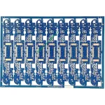
UGPCB の導入 ロボットモーターコントロールPCB, 高信頼性の両面 プリント基板 ロボットモーションコントロールシステム専用に設計. この製品は、Kingboard KB6160A 銅張エポキシ ガラス ファブリック ラミネートを使用しており、IPC-4101E/21 仕様要件に厳密に従っています。. 優れた耐熱性を実現する材料, 機械的強度, および電気的性能. これらの品質により、ロボット モーターの駆動および制御アプリケーションに強固なハードウェア基盤が提供されます。.
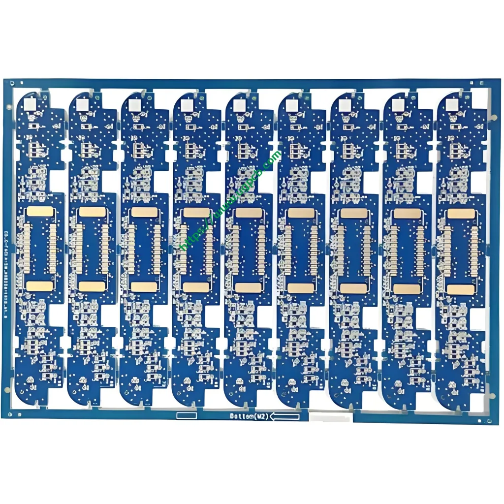
これロボットモーター制御回路基板 対策 96.83 × 30.6 mm付き 1.6 板厚mm. 両面配線構造を採用しています。 (2 レイヤー) コンパクトなロボット制御システムのスペース要件を満たします. この製品の最小絞りは次のとおりです。 0.27 mm, トレースの幅/間隔 0.32/0.382 mm, と銅箔の厚さ 35/35 μm (1 両面にオンスの銅). 表面処理はOSPを使用 (有機はんだ付け性保存剤) 酸化防止仕上げ. ソルダーマスクの色は青色です, そして伝説は白く現れる.
製品の定義と規格への準拠
TheロボットモーターコントロールPCB ロボット関節ドライブ用の特殊なプリント基板です。, サーボモーター制御, モーションコントロールカード, および同様のアプリケーション. この PCB はモーター駆動信号を送信します, 力を分配する, 制御ロジックを実行します. ロボットの重要なコンポーネントとして機能します。 “神経系。”
この製品は、以下の国際規格に厳密に従って製造および設計されています。:
- IPC-4101E/21 (リジッド・多層プリント基板用基材仕様): KB6160A ラミネートはこの仕様を満たしています.
- IPC-6012E (リジッドプリント基板の認定および性能仕様): これは、両面基板の認定要件と性能要件をカバーします。.
- IPC-A-600K (プリント基板の適合性): これは図示された合格基準として機能します.
- IPC-4555 (プリント基板用高温有機はんだ付け性保存剤の性能仕様): これは OSP の表面仕上げプロセスを制御します.
- UL 94 V-0 (可燃性規格): これは最高の難燃性評価を表します.
データソース: 上記の標準情報は IPC からのものです (エレクトロニクス産業をつなぐ協会) 公式規格書とUL (引き受けの研究所) 安全規格.
デザインのハイライト
材料の選択 – KB6160A の主な利点
KB6160A は、Kingboard Laminates Holdings の従来の FR-4 エポキシ ガラス ファブリック銅張積層板です。. 主要なパフォーマンスパラメータを以下に示します:
| 財産 | テスト方法 (IPC-TM-650) | 仕様 | 代表値 |
|---|---|---|---|
| ガラス転移温度 (TG) | 2.4.25 (DSC) | ≧130℃ | 135℃ |
| 熱応力 (288はんだ浮き℃) | 2.4.13.1 | ≥10秒 | ≥180秒 |
| CTE (A1) z軸 | 2.4.24 (TMA) | - | 58 ppm/℃ |
| CTE (A2) z軸 | 2.4.24 (TMA) | - | 286 ppm/℃ |
| 熱分解温度 (TD) | 2.4.24.6 (TGA) | - | 305℃ |
| 可燃性 (炎の評価) | UL 94 | V-0 | V-0 |
| 表面抵抗率 | 2.5.17.1 | ≧1.0×10⁴ MΩ | 1.0×10⁶MΩ |
| 体積抵抗率 | 2.5.17.1 | ≧1.0×10⁶ MΩ・cm | 1.0×10⁸MΩ・cm |
| 誘電率 (@1MHz) | 2.5.5.2 | ≤5.4 | 4.58 |
| 損失係数 (@1MHz) | 2.5.5.2 | ≤0.035 | 0.022 |
| 銅剥離強度 (125℃) | 2.4.8 | ≧0.70N/mm | 1.70 N/mm |
| 曲げ強度 (ワープ) | 2.4.4 | ≥415 N/mm² | 565 N/mm² |
データソース: 上記のデータは、Kingboard Laminates Holdings の公式製品技術文書および IPC-TM-650 試験方法規格から取得したものです。.
KB6160A ラミネートは、次のコア機能を提供します:
- UVB ブロックと AOI の互換性: この素材は紫外線遮断と 自動光学検査 (あおい). これにより、PCB 生産の効率と精度が向上します。.
- 優れた寸法安定性: 一般的な反り値は以下の値に達します 0.17%/0.35%, well below the IPC standard requirement of ≤1.0%.
- 優れた熱性能: ガラス転移温度≧130℃ (典型的な135℃) 288℃のはんだフロートで180秒以上の耐熱ストレス性.
- 優れた機械的特性: 一般的な曲げ強さは次の値に達します 565 N/mm².
トレース幅/間隔および開口部の設計
この製品の特徴は最小絞りです。0.27 mm トレースの幅/間隔0.32/0.382 mm. IPC-2221によると, IPC-2220 シリーズのすべての文書の基礎設計標準, 導体の通電容量は次の式に従います。:
I = k × ΔT^0.44 × A^0.725
ここで、I は電流容量を表します (あ), k は補正係数です (0.024 インナーレイヤー用, 0.048 外層用), ΔT は温度上昇です (℃), A は導体の断面積です (ミル平方). 外層導体温度上昇10℃の場合, a 0.32 トレース幅 mm (約 12.6 ミル) と 35 μm (1 オンス) 銅の厚さは約1.2 あ 電流容量. この設計は、ロボット モーター制御アプリケーションの信号伝送と中程度の電流駆動要件を完全にサポートします。.
基板の厚さと層の積層数
The 1.6 mm 板厚はリジッドの標準的な板厚を表します。 プリント基板. 機械的強度と電気的性能のバランスをとります. The 両面 (2-層) 配線構造により、限られたスペース内で効果的な電源層と信号層の分割が可能. これはロボットモーター制御回路の機能分割原則を満たしています。, モータードライブを明確に分離, メインコントローラー, センサーインターフェース, および電源管理モジュール.
動作原理
TheロボットモーターコントロールPCB として機能します “神経中枢” ロボットシステム内で. その動作原理はいくつかの層を通して理解できます:
信号伝送: PCB 上の銅配線は、メイン MCU からの制御信号を正確に送信する電気ネットワークを形成します。 (マイクロコントローラー) ゲートドライバーやプリドライバーなどのモータードライバーチップまで. The 0.32 mmのトレース幅により信号の完全性が保証されます. The 0.27 mmの最小口径はQFNやBGAを含む高密度コンポーネントパッケージをサポートします.
パワードライブ: 両面 1 オンス (35 μm) 銅は、モータードライブに必要な過渡的な大電流に十分な電流容量を提供します。. 熱放散を促進するために、高出力コンポーネントが基板端近くに配置されています。.
電磁互換性 (EMC): 適切な接地設計と配線戦略により、電磁干渉が効果的に抑制されます。 (エミ) モーターの整流中に生成される. これにより、システム全体でクリーンな制御信号が保証されます。.
製品の用途
これロボットモーター制御回路基板 次のアプリケーションに役立ちます:
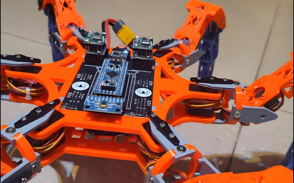
- 産業用ロボットの関節駆動制御: 多軸ロボットアームのサーボモーター制御
- サービスロボットの動作制御: 配送ロボットとガイドロボットのシャーシ駆動と車輪速度のフィードバック
- 教育用ロボットプラットフォーム: 教育および実験用ロボット工学用の制御ボード
- UAV飛行制御システム: モーターの速度調整と制御
- スマートホームオートメーション: 電動カーテンやスマートロックのモーター駆動制御
- OA機器: プリンターやコピー機のモーター制御
- 通信機器: 基地局およびスイッチ用の冷却ファンモーター制御
製品分類
この製品は、国際的なプリント基板規格に従って、複数の次元にわたって科学的に分類できます。:
| 分類次元 | カテゴリ | 準拠規格 |
|---|---|---|
| 基材の種類 | リジッドFR-4プリント基板 | IPC-4101E/21 |
| 導電層数 | 両面基板 (2-層) | IPC-6012E |
| ビアの種類 | メッキスルーホール (PTH) 両面基板 | IPC-6012E |
| 火炎遅延 | UL 94 V-0 評価済み | UL 94 |
| 表面仕上げ | OSP (有機はんだ付け性保存剤) | IPC-4555 |
| アプリケーションドメイン | ロボット工学/産業用制御 PCB | - |
データソース: 分類基準はIPC-4101Eに基づく, IPC-6012E, IPC-4555, およびUL 94 国際仕様.
使用材料
基材 – KB6160A 銅被覆エポキシガラスファブリックラミネート
KB6160A は、FR-4 エポキシガラス布銅張積層板 家族. その材料構成には以下が含まれます::
- 強化: 電子グレードの E ガラス生地
- バインダー: 難燃性エポキシ樹脂
- 銅箔: 電着塗装 (編) 銅, 35 μm (1 オンス) 厚さ
- 難燃システム: UL 94 V-0 適合した難燃性添加剤
表面仕上げ – OSP (有機はんだ付け性保存剤)
OSP は、裸の銅表面に塗布される薄い有機コーティングです。. 銅の酸化を防ぎ、はんだ付け性を維持します。. IPC-4555によると, OSP コーティングの保存寿命は最低6か月.
OSP表面仕上げのメリット:
- 費用対効果の高い: ENIGよりも経済的 (エレクトロレスニッケルイマージョンゴールド) またはHASL (熱気はんだレベリング)
- 環境に優しい: 鉛フリーはんだ付けプロセスに完全対応
- 良好なはんだ付け性: ライフサイクルが短から中程度の製品または良好な環境に適しています
はんだマスクと凡例
- はんだマスク: 青色インクは絶縁保護を提供し、はんだブリッジを防止します
- 伝説: コンポーネントの識別と組み立てガイド用の白インク
パフォーマンスパラメータの概要
| パラメーター | 仕様 |
|---|---|
| ラミネートタイプ | KB6160A (キングボード FR-4) |
| 板厚 | 1.6 mm |
| レイヤー数 | 2 レイヤー (両面) |
| 基板サイズ | 96.83 × 30.6 mm |
| 最小開口 | 0.27 mm |
| 最小トレース幅 | 0.32 mm |
| 最小トレース間隔 | 0.382 mm |
| 銅箔の厚さ | 35/35 μm (1 オンスの両面) |
| 表面仕上げ | OSP 酸化防止剤 |
| はんだマスク色 | 青 |
| 凡例の色 | 白 |
| TG (ガラス転移温度) | ≧130℃ (代表値135℃) |
| 炎の評価 | UL 94 V-0 |
| 熱応力 (288℃) | ≥10秒 (通常 ≥180 秒) |
構造的特徴
- 両面配線: 最上層と最下層の両方に回路が搭載されています, 配線密度を効果的に高める
- メッキスルーホール (PTH) デザイン: 層間の電気的相互接続を可能にします
- OSP表面保護: 銅表面の酸化保護により、はんだ付けの信頼性が保証されます
- 白い凡例が付いた青いはんだマスク: 明確な視覚的コントラストにより、組み立てと検査が容易になります
- 1.6 mm標準板厚: 機械的強度と標準化された製造のバランスをとる
製造工程
UGPCB は、ロボットモーターコントロールPCB この標準化されたプロセスフローを通じて:
- 材料の切断: 大型のKB6160A銅張パネルは生産パネルのサイズに合わせてカットされます
- 掘削: CNC 数値制御穴あけ加工により、 0.27 mm最小口径
- 無電解銅・パネルメッキ: 銅の化学蒸着とそれに続くホールメタライゼーションのためのパネル電気めっき
- 外層パターン転写: ラミネート→露光→現像で回路パターンを作成
- パターンメッキ: 銅および錫鉛レジストが回路パターン上に電気めっきされます
- エッチング: 露出した銅箔を除去して最終回路を形成します
- 錫剥離: 錫鉛レジストを除去
- OSP表面処理: IPC-4555に従ってOSP有機はんだ付け性保護剤が適用されています
- ソルダーマスク印刷: 青色のソルダーマスクインクを塗布, 露出, そして開発された
- 凡例の印刷: 白い識別文字がスクリーン印刷されています
- プロファイルルーティング: CNC ルーティングが最終的な形状を形成 96.83 × 30.6 mm寸法
- 電気試験: フライングプローブまたはユニバーサルテストでオープン/ショート状態を検証
- 最終検査: IPC-A-600Kに準拠した目視および寸法検査
- 梱包と発送: 湿気を遮断した真空包装
アプリケーションシナリオ
シナリオ 1: 産業用ロボットのサーボドライブ制御
6軸産業用ロボットでは, これプリント基板 サーボドライバー制御ボードとして機能します. ホストコンピュータからモーションコマンドを受信します. PWM 制御信号が通過します。 0.32 IGBT または MOSFET ドライバー段までの mm トレース, サーボモーターの正確なトルクと速度制御を実現.
シナリオ 2: サービスロボットシャーシドライブ
配送ロボットやAGVにおいて (無人搬送車), これ回路基板 デュアルモーター独立駆動制御の中核として機能. 左右の駆動輪の速度とステアリングを独立して制御します, 直線移動とその場回転が可能.
シナリオ 3: 教育用ロボット開発プラットフォーム
大学のロボット研究室やメーカースペースなど, これロボットモーター制御基板 ロボット制御システムのコアボードとして機能します. FOCを含むモーター駆動アルゴリズムの学生の開発と検証をサポートします。 (フィールド指向制御) およびPID速度調整.
シナリオ 4: UAV モーター速度制御
クアッドコプターの場合, この PCB は ESC として機能できます (電子スピードコントローラー) 制御盤. フライトコントローラーのコマンドをモーター駆動信号に変換します。, ブラシレスモーターの高速応答制御を実現.
UGPCB のロボット モーター制御 PCB が選ばれる理由?
- 完全な国際規格準拠: 製品はIPC-4101E/21に従って設計および製造されています, IPC-6012E, IPC-A-600K, IPC-4555, およびUL 94 V-0
- プレミアム素材保証: Kingboard KB6160A FR-4 ラミネート、Tg ≥130℃, UL 94 V-0 炎の評価, かつ 180 秒以上の熱応力耐性
- 高精度の製造: 0.27 mm最小口径と 0.32 mmの最小トレース幅は高密度配線要件を満たします
- ワンストップサービス: PCB 設計の最適化とコンポーネントの調達から SMT/DIP アセンブリと機能テストに至るまでのフルチェーンのサポート
- 10+ 長年の業界経験: サーブオーバー 3,000 世界中の企業顧客
UGPCB は世界をリードする PCB 設計プロバイダーです, 製造業, およびPCBAアセンブリサービス. に設立されました 2014, 同社は、世界中の顧客に高精度で信頼性の高い PCB ソリューションを提供することに尽力しています。.
今すぐ見積もりとサンプルを入手してください
UGPCB はあなたのロボットモーターコントロールPCB とのプロジェクト:
- ✅ 無料のDFM (製造用のデザイン) レポート
- ✅ ラピッドプロトタイピング 24-時間 配達可能
- ✅ 大量生産 20%+ 業界平均を上回る歩留まり
- ✅ 技術サポートを提供する専門のエンジニアリングチーム
📧無料お見積りについてはお問い合わせください: UGPCB Web サイトにアクセスして、ガーバー ファイルと BOM を送信してください。. 業界をリードする自動見積もりを受け取る.
📞ホットライン: 当社ウェブサイトのオンラインチャットまたは電子メールを通じてご連絡ください.
データソース宣言
この記事で引用されているすべての技術データと標準情報は、次の信頼できる情報源から取得されています。:
- キングボード・ラミネート・ホールディングス株式会社. — KB-6160A 製品技術資料 (KB 技術情報)
- IPC (エレクトロニクス産業をつなぐ協会) — IPC-4101E/21 リジッドおよび多層プリント基板用基材仕様, IPC-6012E リジッドプリント基板の認定および性能仕様, IPC-A-600K プリント基板の適合性, IPC-4555 高温有機はんだ付け性防腐剤の性能仕様 (OSP) プリント基板用, IPC-TM-650 試験方法マニュアル, IPC-2221 プリント基板設計に関する一般規格
- UL (引き受けの研究所) — UL 94 機器・家電部品のプラスチック材料の燃焼性試験に関する規格
- PCBWay 材料データベース — KB-6160/6160A/6160C の技術パラメータ
- OSHPark 技術文書 — KB6160A 基板仕様シート
免責事項: 上記の典型的な値は、参考のためにのみ提供された臨床検査データです。. 実際の製品の性能は製造プロセスや使用環境によって異なる場合があります.













