

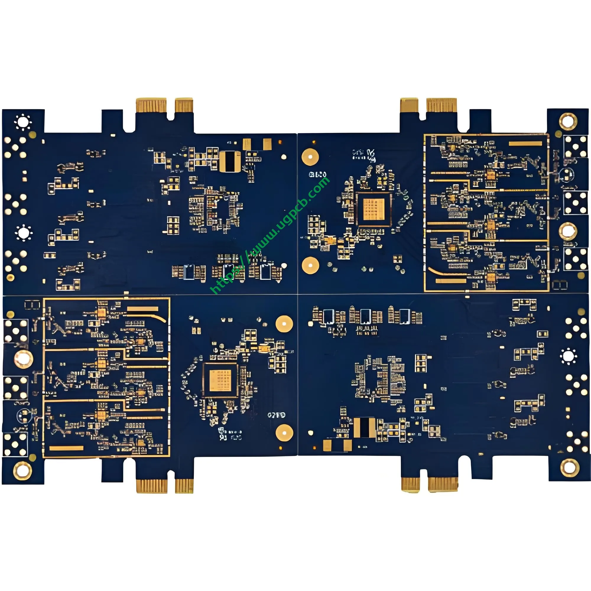
نظرة عامة على المنتج: ما هو القرص الصلب الميكانيكي للكمبيوتر ثنائي الفينيل متعدد الكلور?
قرص صلب ميكانيكي للكمبيوتر ثنائي الفينيل متعدد الكلور (لوحة الدوائر المطبوعة) هو عنصر التحكم الكهربائي الأكثر أهمية داخل محرك الأقراص الثابتة (الأقراص الصلبة). تحمل هذه اللوحة شريحة التحكم الرئيسية, ذاكرة التخزين المؤقت, دوائر إدارة الطاقة, وموصلات واجهة مختلفة. يقوم بتنسيق عمليات القراءة/الكتابة للرأس, التحكم في محرك المغزل, واتصالات البيانات بين المضيف ووسائط التخزين.
يقدم UGPCB هذاالقرص الصلب الميكانيكي للكمبيوتر ثنائي الفينيل متعدد الكلور المصنعة وفقا لمعايير الصناعة مادة الألياف الزجاجية FR4. يبلغ سمك اللوحة 1.6 ملم مع وجهين (2-طبقة) تصميم. أبعادها الدقيقة هي 53.68 × 42.7 ملم, مصمم خصيصًا لأجهزة تخزين القرص الصلب الميكانيكية مقاس 3.5 بوصة. كما “المركز العصبي” من القرص الصلب, تحدد جودة وأداء PCB هذا معدلات نقل البيانات بشكل مباشر, استقرار القراءة/الكتابة, وعمر الخدمة الشامل.
في عالم اليوم القائم على البيانات, تحتفظ الأقراص الصلبة الميكانيكية بمكانة لا يمكن الاستغناء عنها في مراكز البيانات, أجهزة الكمبيوتر الشخصية, المراقبة الأمنية, والتخزين السحابي نظرًا لسعتها الكبيرة والتكلفة المنخفضة لكل جيجابايت. باعتبارها المكون الأساسي لمحركات الأقراص الصلبة, اللوحة دوائر القرص الصلب يتطلب جودة وموثوقية استثنائية.
تعريف المنتج والتصنيف العلمي
تعريف المنتج
أالقرص الصلب الميكانيكي للكمبيوتر ثنائي الفينيل متعدد الكلور عبارة عن لوحة دوائر مطبوعة صلبة مصممة خصيصًا للاستخدام الداخلي داخل محركات الأقراص الثابتة الميكانيكية (الأقراص الصلبة). يحمل وحدة التحكم الرئيسية, ذاكرة التخزين المؤقت, دوائر إدارة الطاقة, وموصلات الواجهة لتمكين التحكم في قراءة/كتابة البيانات, محرك السيارات, والاتصالات المضيفة.
التصنيف العلمي
لكل IPC-6012Fمواصفات التأهيل والأداء للألواح المطبوعة الصلبة, يقع هذا المنتج ضمن فئات التصنيف العلمي التالية:
| البعد التصنيفي | فئة |
|---|---|
| حسب الهيكل | لوحة مطبوعة صلبة على الوجهين |
| حسب عدد الطبقات | 2-لوحة الطبقة (2ل) |
| حسب النوع | مع فتحات مطلية (PTH) |
| بواسطة الركيزة | FR4 إيبوكسي الألياف الزجاجية |
| حسب تصنيف القابلية للاشتعال | أول 94 V-0 (أعلى تصنيف مثبطات اللهب) |
| بواسطة الانتهاء من السطح | طلاء الذهب |
| بواسطة فئة الأداء IPC | فصل 2 (منتجات إلكترونية مخصصة للخدمة) |
لكل IPC-6012F, هذا المنتج هولوح مطبوع صلب على الوجهين مزود بفتحات مطلية. يفي بفئة IPC 2 متطلبات المعدات الإلكترونية للخدمة المخصصة, ضمان الموثوقية في ظل التشغيل المستمر لمحرك الأقراص الصلبة, التغيرات في درجات الحرارة, والتداخل الكهرومغناطيسي.
مواصفات التصميم والمعايير الفنية
مادة الركيزة: FR4 الألياف الزجاجية
يستخدم هذا المنتج FR4 (مثبطات اللهب 4) كمادة أساسية, الصفائح الصلبة الأكثر استخدامًا على نطاق واسع في صناعة ثنائي الفينيل متعدد الكلور. يتكون FR4 من مادة رابطة من راتنجات الإيبوكسي معززة بقطعة قماش منسوجة من الألياف الزجاجية. وتشمل المزايا الرئيسية:
- قوة ميكانيكية متفوقة: يوفر تعزيز الألياف الزجاجية قوة انثناء ممتازة واستقرارًا للأبعاد
- عزل كهربائي متميز: مقاومة عالية الحجم وثابت عازل مستقر
- أول 94 V-0 تصنيف القابلية للاشتعال: اللهب ينطفئ ذاتيا في الداخل 10 ثواني بعد إزالة اللهب دون أن يقطر
- مقاومة حرارية ممتازة: TG (درجة حرارة التحول الزجاجي) ≥135 درجة مئوية, متوافق مع عمليات اللحام الخالية من الرصاص
سمك اللوحة وعدد الطبقات: 1.6مم تصميم على الوجهين
سمك اللوحة: 1.6مم - وهذا يمثل “سمك ذهبي” في صناعة ثنائي الفينيل متعدد الكلور والمواصفات الأكثر شيوعًا للوحات الصلبة ذات الوجهين وفقًا لـ IPC-6012. يحقق سمك 1.6 ملم التوازن الأمثل بين القوة الميكانيكية, مقاومة الانحناء, وتكلفة التصنيع.
لكل IPC-6012F, التسامح مع سمك اللوحة النهائية لسمك اسمي 1.6 مم هو± 10 ٪, تحقيق نطاق مقبول من1.44ملم إلى 1.76 ملم.
عدد الطبقات: 2 طبقات (2ل) - يلبي التصميم ذو الوجهين متطلبات تعقيد التوجيه لدوائر القرص الصلب مع تحقيق التوازن الأمثل بين التكلفة والأداء. تحمل كل من الطبقات العلوية والسفلية آثارًا, مع ثقوب مطلية (PTH) توفير التوصيلات الكهربائية بين الطبقات.
مواصفات الأبعاد الدقيقة
أبعاد المخطط التفصيلي: 53.68 × 42.7 ملم
يقوم UGPCB بتخصيص هذه الأبعاد بدقة استنادًا إلى معايير صناعة الأقراص الصلبة الميكانيكية السائدة مقاس 3.5 بوصة, ضمان التوافق المادي مع حاوية القرص, محرك المغزل, ومجموعة ذراع المحرك. يستخدم الطول 53.68 ملم والعرض 42.7 ملم المساحة الداخلية المحدودة للقرص الصلب بشكل كامل مع زيادة مساحة الدائرة الوظيفية إلى أقصى حد.
معلمات التوجيه الدقيقة
الحد الأدنى لقطر الثقب: 0.22مم
يمثل الحد الأدنى لقطر الثقب 0.22 مم متطلبات دقة حفر ميكانيكية عالية نسبيًا. نسبة الارتفاع (سمك اللوح إلى قطر الثقب) يكون1.6 / 0.22 ≈ 7.27:1, جيدًا ضمن الحد الأعلى للحفر الميكانيكي التقليدي وهو ≥8:1. وهذا يضمن سماكة وموثوقية موحدة لطلاء النحاس على جدران الفتحات.
عرض الخط / تباعد الخط: 0.37 × 0.42 ملم
يضمن التوجيه الدقيق بعرض الخط 0.37 مم وتباعد الخط 0.42 مم سلامة الإشارة مع توفير مساحة توجيه كافية لحافلات البيانات عالية السرعة. تحقق مجموعة المعلمات هذه توازنًا مثاليًا بين إنتاجية التصنيع والأداء الكهربائي.
سمك رقائق النحاس: 35/35ميكرومتر (1 أوقية)
يتم قياس رقائق النحاس من الطبقة العلوية والسفلية35ميكرومتر (1 أوقية) , يمثل سمك النحاس الموصل الخارجي النموذجي للألواح المطبوعة الصلبة وفقًا لـ IPC-6012F.
لكل IPC-D-275, يتم حساب قدرة الحمل الحالية للموصل الخارجي على النحو التالي:
أنا = 0.0647 × (ΔT)^0.4281 × (أ)^0.6734
أين:
- I = الحد الأقصى لقدرة الحمل الحالية (أ)
- ΔT = ارتفاع درجة الحرارة المسموح به (درجة مئوية)
- A = مساحة المقطع العرضي للموصل (مم²)
لرقائق النحاس 35 ميكرومتر بعرض خط 1 مم, مساحة المقطع العرضي للموصل A = 0.035mm². عند ارتفاع درجة الحرارة بمقدار 10 درجات مئوية, يمكن لهذا الموصل أن يحمل تقريبًا1.0أ.
بعرض خط 0.37 ملم, القدرة الاستيعابية الحالية المقابلة تقريبًا0.37أ (عند ارتفاع درجة الحرارة بمقدار 10 درجات مئوية), تلبية المتطلبات الحالية لخطوط الإشارة والطاقة في دوائر القرص الصلب بشكل كامل.
الانتهاء من السطح: طلاء الذهب
يستخدم هذا المنتجطلاء الذهب كما الانتهاء من السطح, مع طبقة النيكل (2-3ميكرومتر) أودعت أولا, تليها طبقة ذهبية (≥0.025μm) على أسطح الوسادة.
المزايا الرئيسية لطلاء الذهب:
- مقاومة التآكل استثنائية: تتحمل طبقة الذهب الصلب دورات التزاوج المتكررة
- مقاومة الاتصال منخفضة للغاية: يضمن نقل إشارة مستقر وموثوق
- قابلية لحام ممتازة: سطح الذهب يقاوم الأكسدة, تمكين موثوقية لحام عالية
- استقرار التخزين على المدى الطويل: تحمي الطبقة الذهبية الأسطح النحاسية بشكل فعال من الأكسدة والتآكل
تعمل طبقة النيكل كحاجز انتشار, منع الانتشار المتبادل بين النحاس والذهب وتجنب تكوين مركبات بين معادن النحاس والذهب الهشة, ضمان الموثوقية على المدى الطويل بشكل أساسي.
قناع اللحام والأسطورة: قناع أزرق بأحرف بيضاء
لون قناع اللحام: أزرق
يوفر قناع اللحام الأزرق تعريفًا بصريًا مميزًا بينما يوفر حماية عزل ممتازة ومقاومة للرطوبة. يغطي قناع اللحام جميع مناطق التوجيه باستثناء الوسائد, يمنع بشكل فعال سد اللحام والدوائر القصيرة أثناء التجميع.
لون الأسطورة: أبيض
طباعة الأسطورة البيضاء على قناع اللحام الأزرق تخلق تباينًا عاليًا. المحددات المرجعية للمكونات, علامات القطبية, وتبقى معلومات الإصدار واضحة المعالم, يسهل بشكل كبير وضع SMT والفحص والإصلاح اللاحق.
مبدأ التشغيل: كيف يقوم HDD PCB بتخزين البيانات?
يعمل القرص الصلب الميكانيكي للكمبيوتر PCB على المستويات التالية:
فك تشفير الأوامر وتنفيذها
عندما يرسل الكمبيوتر أوامر القراءة/الكتابة إلى القرص الصلب, تنتقل هذه الأوامر عبر واجهة SATA إلى شريحة التحكم الموجودة على PCB. تقوم شريحة التحكم بفك تشفير الأوامر وإرسال إشارات التحكم من خلال آثار PCB إلى مشغل المحرك ومحرك المغزل.
التحكم في قراءة/كتابة البيانات
تتكون قناة القراءة/الكتابة الموجودة على PCB من مضخم أولي, دوائر القراءة/الكتابة, وساعة المزامنة. أثناء عمليات القراءة, تمر الإشارات المغناطيسية الضعيفة التي يستشعرها رأس القراءة/الكتابة عبر المضخم ويتم تحويلها بواسطة قناة القراءة/الكتابة إلى إشارات رقمية, ثم ينتقل إلى المضيف من خلال الواجهة. عمليات الكتابة تتبع المسار العكسي.
إدارة الطاقة
تعمل وحدة إدارة الجهد/التيار الموجودة على PCB على تحويل طاقة +5V و+12V من المضيف إلى الفولتية المتنوعة التي تتطلبها مكونات HDD المختلفة. تنفذ هذه الوحدة أيضًا وظائف إدارة الطاقة المتقدمة بما في ذلك تحسين الطاقة, وضع السكون التلقائي, وحماية المبادلة الساخنة.
ذاكرة التخزين المؤقت للبيانات والبرامج الثابتة
تقوم شريحة ذاكرة التخزين المؤقت الموجودة على PCB بتخزين البيانات التي يتم الوصول إليها بشكل متكرر مؤقتًا لتحسين أداء القراءة/الكتابة. تقوم شريحة البرنامج الثابت بتخزين الرمز الصغير التشغيلي لمحرك الأقراص الثابتة, التحكم في المنطق الأساسي بما في ذلك وضع الرأس, إدارة القطاع السيئ, والمراقبة الذكية.
مواصفات الأداء ومعايير الجودة
الأداء الكهربائي
| المعلمة | مواصفة | المعيار المرجعي |
|---|---|---|
| مقاومة العزل | ≥10⁶ مΩ | IPC-6012F |
| عازلة تحمل الجهد | ≥500VAC (1 دقيقة) | IPC-6012F |
| مقاومة الموصل | .01.0mΩ/سم | IPC-6012F |
| الممانعة المميزة | التحكم لكل تصميم | IPC-6012F |
الأداء الميكانيكي
| المعلمة | مواصفة | المعيار المرجعي |
|---|---|---|
| التسامح سمك المجلس | ± 10 ٪ (1.44-1.76 ملم) | IPC-6012F |
| سمك جدار الثقب النحاسي | ≥20μm (فصل 2) | IPC-6012F |
| قوة التقشير | ≥1.1N/مم | IPC-6012F |
| تصنيف القابلية للاشتعال | أول 94 V-0 | أول 94 |
التفتيش البصري والأبعاد
لكل IPC-A-600Kقبول اللوحات المطبوعة, يجب أن تمر مركبات ثنائي الفينيل متعدد الكلور النهائية بفحص بصري صارم (3 تكبير الديوبتر, حوالي 1.75x) لضمان عدم وجود خدوش, فقاعات, النحاس المكشوف, أو عيوب أخرى.
عملية التصنيع ومراقبة الجودة
تدفق الإنتاج القياسي
- قطع: صفائح نحاسية FR4 مقطوعة حسب حجم اللوحة
- حفر: 0.22الحفر الميكانيكي بدقة مم
- النحاس غير الكهربائي / طلاء اللوحة: الترسيب الكيميائي + الطلاء الكهربائي للوحة كاملة
- نقل النمط: تصفيح الفيلم الجاف ← التعرض ← التطوير ← النقش
- طلاء النمط: تراكم طبقة النحاس حتى 35μm
- يجرد / حفر / يجرد: تشكيل نمط الدائرة النهائية
- طباعة قناع اللحام: قناع اللحام الأزرق بالشاشة الحريرية + علاج
- طباعة الأسطورة: أسطورة بيضاء بالشاشة الحريرية
- طلاء الذهب: طلاء بالنيكل والذهب على أسطح الوسادة
- التوجيه: التوجيه باستخدام الحاسب الآلي إلى 53.68 × 42.7 ملم مخطط تفصيلي
- اختبار الكهربائية: مسبار الطيران / تركيبات اختبار مفتوحة قصيرة
- تفتيش FQC: 100% مراقبة الجودة النهائية وفقًا لـ IPC-A-600K
نظام مراقبة الجودة
تطبق UGPCB فئة IPC-6012F بصرامة 2 معايير مع مراقبة الجودة الشاملة من المواد الواردة إلى الشحن:
- التفتيش الوارد: 100% فحص شرائح FR4, رقائق النحاس, الأحبار, وغيرها من المواد الخام
- التحكم في العملية: نقاط فحص الجودة في كل خطوة من خطوات العملية مع مراقبة SPC
- تفتيش المنظمة العربية للتصنيع: 100% الفحص البصري التلقائي لعيوب الدائرة
- اختبار الموثوقية: اختبار الصدمة الحرارية, اختبار الرطوبة, اختبار قابلية اللحام
سيناريوهات التطبيق والقيمة السوقية
سيناريوهات التطبيق الأساسي
| منطقة التطبيق | حالة استخدام محددة | متطلبات ثنائي الفينيل متعدد الكلور |
|---|---|---|
| أجهزة الكمبيوتر الشخصية | القرص الصلب لسطح المكتب, هارد ديسك خارجي لأجهزة الكمبيوتر المحمول | موثوقية عالية, عمر خدمة طويل |
| مراكز البيانات | خوادم التخزين السحابية, مصفوفات تخزين المؤسسة | 24/7 عملية مستمرة |
| المراقبة الأمنية | مسجلات فيديو شبكية NVR, خوادم تخزين الفيديو | قدرة عالية على الكتابة المستمرة |
| الالكترونيات الاستهلاكية | وحدات تحكم اللعبة, صناديق فك التشفير, أجهزة التلفاز الذكية | الأمثل من حيث التكلفة, عملية مستقرة |
| استعادة البيانات | استبدال وإصلاح خلل HDD PCB | التوافق الدقيق, التوصيل والتشغيل |

توقعات السوق
بحسب QYR (QYResearch) إحصائيات, يحافظ سوق ثنائي الفينيل متعدد الكلور للقرص الصلب الميكانيكي العالمي على نمو مطرد. على الرغم من محركات الأقراص ذات الحالة الصلبة (محركات أقراص الحالة الصلبة) تخترق السوق الاستهلاكية بسرعة, تستمر الأقراص الصلبة الميكانيكية في الهيمنة على وحدات التخزين عالية السعة (8السل وما فوق), التخزين البارد لمركز البيانات, وتطبيقات المراقبة الأمنية بسببميزة التكلفة لكل جيجابايت وموثوقية الاحتفاظ بالبيانات على المدى الطويل.
لماذا تختار ثنائي الفينيل متعدد الكلور للقرص الصلب الميكانيكي للكمبيوتر الخاص بـ UGPCB?
المزايا التقنية
- تم تصنيعها بدقة وفقًا للمواصفات الدولية IPC-6012F
- 1.6توفر الركيزة FR4 مم مع رقائق النحاس على الوجهين مقاس 35 ميكرومتر القوة الميكانيكية والأداء الكهربائي
- 0.22قطر الثقب الدقيق مم مع عرض/تباعد الخط الدقيق 0.37/0.42 مم يدعم متطلبات التوجيه عالية الكثافة
ضمان الجودة
- يوفر السطح المطلي بالذهب مقاومة اتصال منخفضة, قابلية لحام ممتازة, واستقرار التخزين على المدى الطويل
- يوفر قناع اللحام الأزرق مع الأسطورة البيضاء تباينًا عاليًا, تحديد سهل, مقاومة الرطوبة, والعزل
- 100% يضمن الاختبار الكهربائي بالإضافة إلى فحص AOI شحنًا خاليًا من العيوب لكل ثنائي الفينيل متعدد الكلور
التزام الخدمة
- يدعم كلا من النماذج الأولية بكميات صغيرة والإنتاج بكميات كبيرة
- يوفر سوق دبي المالي الاحترافي (تصميم للتصنيع) مراجعة
- تسليم سريع لتلبية احتياجات الإصلاح والإنتاج الضخم العاجلة
اطلب عرض أسعار - احصل على حل HDD PCB المخصص اليوم
سواء كنت شركة مصنعة للقرص الصلب, مزود خدمة استعادة البيانات, أو تكامل نظام المراقبة الأمنية, توفر UGPCB مركبات ثنائي الفينيل متعدد الكلور للأقراص الصلبة الميكانيكية للكمبيوتر عالية الجودة ومصممة خصيصًا لتلبية احتياجاتك.
اتصل بنا اليوم ل:
- أوراق بيانات المنتج وتقارير اختبار الموثوقية
- خدمات التصميم المخصص ومراجعة سوق دبي المالي
- التسعير الحجمي ومقترحات جدول التسليم
👉انقر للاستفسار – سيقوم الفريق الفني لـ UGPCB بالرد في الداخل 24 ساعات مع الحل المخصص الخاص بك!
إعلان مصدر البيانات
المعايير الفنية والبيانات المذكورة في هذه الوثيقة مستمدة من المصادر الرسمية التالية:
- IPC-6012F: مواصفات التأهيل والأداء للألواح المطبوعة الصلبة, IPC - الجمعية العالمية للإلكترونيات, أكتوبر 2023
- IPC-A-600K: قبول اللوحات المطبوعة, IPC - الجمعية العالمية للإلكترونيات, يوليو 2020
- إيبك-د-275: معيار التصميم للألواح المطبوعة الصلبة وتجميعات الألواح المطبوعة الصلبة
- أول 94: معيار السلامة من القابلية للاشتعال للمواد البلاستيكية, مختبرات الضامنين
- IPC-6012F تحمل سمك اللوحة: السُمك الاسمي ±10% (1.44ملم – 1.76 ملم)













