


نظرة عامة على المنتج
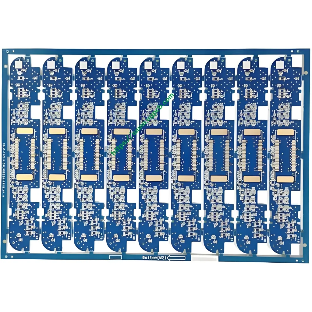
يقدم UGPCB التحكم في محرك الروبوت ثنائي الفينيل متعدد الكلور, موثوقية عالية على الوجهين لوحة الدوائر المطبوعة مصممة خصيصًا لأنظمة التحكم في الحركة الروبوتية. يستخدم هذا المنتج صفائح نسيج زجاج إيبوكسي مطلية بالنحاس Kingboard KB6160A ويتبع بدقة متطلبات مواصفات IPC-4101E/21. توفر المادة مقاومة حرارية ممتازة, القوة الميكانيكية, والأداء الكهربائي. توفر هذه الصفات أساسًا متينًا للأجهزة لتشغيل المحركات الآلية وتطبيقات التحكم.
هذالوحة دائرة التحكم بمحرك الروبوت مقاسات 96.83 × 30.6 مم مع أ 1.6 سمك اللوح مم. ويتميز بهيكل الأسلاك على الوجهين (2 طبقات) التي تلبي متطلبات المساحة لأنظمة التحكم الروبوتية المدمجة. يوفر المنتج الحد الأدنى من الفتحة 0.27 مم, عرض التتبع/تباعد 0.32/0.382 مم, وسمك رقائق النحاس 35/35 ميكرومتر (1 أوقية النحاس على كلا الجانبين). تستخدم المعالجة السطحية OSP (المواد الحافظة العضوية القابلة للحام) لمسة نهائية مضادة للأكسدة. قناع اللحام يأتي باللون الأزرق, وتظهر الأسطورة باللون الأبيض.
تعريف المنتج والامتثال للمعايير
الالتحكم في محرك الروبوت ثنائي الفينيل متعدد الكلور عبارة عن لوحة دوائر مطبوعة متخصصة لمحركات المفاصل الآلية, التحكم في المحركات المؤازرة, بطاقات التحكم في الحركة, والتطبيقات المماثلة. ينقل ثنائي الفينيل متعدد الكلور إشارات محرك المحرك, يوزع الطاقة, وينفذ منطق التحكم. إنه يعمل كعنصر حاسم في الروبوت “الجهاز العصبي.”
يخضع هذا المنتج للتصنيع والتصميم وفقًا للمعايير الدولية التالية:
- IPC-4101E/21 (مواصفات المواد الأساسية للوحات المطبوعة الصلبة ومتعددة الطبقات): صفح KB6160A يلبي هذه المواصفات.
- IPC-6012E (مواصفات التأهيل والأداء للألواح المطبوعة الصلبة): يغطي هذا متطلبات التأهيل والأداء للألواح ذات الوجهين.
- IPC-A-600K (قبول اللوحات المطبوعة): وهذا بمثابة معيار القبول المصور.
- إيبك-4555 (مواصفات الأداء للمواد الحافظة العضوية القابلة للحام بدرجة الحرارة العالية للوحات المطبوعة): هذا يحكم عملية تشطيب سطح OSP.
- أول 94 V-0 (معيار القابلية للاشتعال): وهذا يمثل أعلى تصنيف لتثبيط اللهب.
مصدر البيانات: المعلومات القياسية المذكورة أعلاه تأتي من IPC (جمعية ربط الصناعات الإلكترونية) الوثائق القياسية الرسمية وUL (مختبرات الضامنين) معايير السلامة.
أبرز التصميم
اختيار المواد – المزايا الأساسية لـ KB6160A
KB6160A عبارة عن صفائح نحاسية تقليدية مغطاة بالنحاس من نسيج زجاج الإيبوكسي FR-4 من Kingboard Laminates Holdings. تظهر معلمات الأداء الرئيسية أدناه:
| ملكية | طريقة الاختبار (IPC-TM-650) | مواصفة | القيمة النموذجية |
|---|---|---|---|
| درجة حرارة انتقال الزجاج (تيراغرام) | 2.4.25 (DSC) | ≥130 درجة مئوية | 135℃ |
| الإجهاد الحراري (288☀ تعويم اللحام) | 2.4.13.1 | ≥10 ثانية | ≥180 ثانية |
| CTE (a1) المحور Z | 2.4.24 (تما) | — | 58 جزء في المليون/درجة مئوية |
| CTE (a2) المحور Z | 2.4.24 (تما) | — | 286 جزء في المليون/درجة مئوية |
| درجة حرارة التحلل الحراري (TD) | 2.4.24.6 (TGA) | — | 305℃ |
| القابلية للاشتعال (تصنيف اللهب) | أول 94 | V-0 | V-0 |
| المقاومة السطحية | 2.5.17.1 | ≥1.0×10⁴ مΩ | 1.0×10⁶ مΩ |
| مقاومة الحجم | 2.5.17.1 | ≥1.0×10⁶ مΩ·سم | 1.0×10⁸ مΩ·سم |
| ثابت العزل الكهربائي (@ 1 ميغاهيرتز) | 2.5.5.2 | .45.4 | 4.58 |
| عامل التبديد (@ 1 ميغاهيرتز) | 2.5.5.2 | .035.035 | 0.022 |
| قوة قشر النحاس (125℃) | 2.4.8 | ≥0.70 ن/مم | 1.70 ن / مم |
| قوة العاطفة (الاعوجاج) | 2.4.4 | ≥415 نيوتن/مم² | 565 ن/مم2 |
مصدر البيانات: البيانات المذكورة أعلاه تأتي من الوثائق الفنية الرسمية للمنتج Kingboard Laminates Holdings ومعايير طريقة الاختبار IPC-TM-650.
تقدم صفائح KB6160A هذه الميزات الأساسية:
- حجب الأشعة فوق البنفسجية (UVB) وتوافق AOI: تدعم المادة حجب الأشعة فوق البنفسجية و الفحص البصري التلقائي (الهيئة العربية للتصنيع). وهذا يحسن كفاءة ودقة إنتاج ثنائي الفينيل متعدد الكلور.
- استقرار الأبعاد ممتازة: تصل قيم صفحة الحرب النموذجية فقط 0.17%/0.35%, أقل بكثير من متطلبات معيار IPC البالغة .01.0%.
- أداء حراري متفوق: تيراغرام ≥130 درجة مئوية (نموذجي 135 درجة مئوية) مع مقاومة الإجهاد الحراري ≥180 ثانية عند درجة حرارة 288 درجة مئوية.
- خصائص ميكانيكية متميزة: تصل قوة الانثناء النموذجية 565 ن/مم2.
تتبع العرض/التباعد وتصميم الفتحة
يتميز هذا المنتج بحد أدنى من الفتحة0.27 مم وتتبع العرض/التباعد0.32/0.382 مم. وفقا ل IPC-2221, معيار التصميم الأساسي لجميع المستندات في سلسلة IPC-2220, تتبع قدرة الحمل الحالية للموصل هذه الصيغة:
أنا = ك × ΔT^0.44 × أ^0.725
حيث أمثل القدرة الاستيعابية الحالية (أ), ك هو عامل التصحيح (0.024 للطبقات الداخلية, 0.048 للطبقات الخارجية), ΔT هو ارتفاع درجة الحرارة (℃), و A هي منطقة المقطع العرضي للموصل (ميل²). لموصلات الطبقة الخارجية عند ارتفاع درجة الحرارة بمقدار 10 درجات مئوية, أ 0.32 عرض التتبع مم (تقريبًا 12.6 ميل) مع 35 ميكرومتر (1 أوقية) سمك النحاس يسلم تقريبا1.2 أ القدرة الحالية. يدعم هذا التصميم بشكل كامل نقل الإشارات ومتطلبات محرك التيار المعتدل لتطبيقات التحكم في المحركات الآلية.
سمك اللوحة وتكديس الطبقة
ال 1.6 مم يمثل سمك اللوح السماكة القياسية للصلبة مركبات ثنائي الفينيل متعدد الكلور. فهو يوازن بين القوة الميكانيكية والأداء الكهربائي. ال على الوجهين (2-طبقة) يتيح هيكل الأسلاك تقسيمًا فعالاً لطبقة الطاقة والإشارة ضمن مساحة محدودة. وهذا يتوافق مع مبادئ التقسيم الوظيفي لدوائر التحكم في المحركات الآلية, فصل محرك السيارات بشكل واضح, وحدة التحكم الرئيسية, واجهة الاستشعار, ووحدات إدارة الطاقة.
مبدأ التشغيل
الالتحكم في محرك الروبوت ثنائي الفينيل متعدد الكلور وظائف كما “المركز العصبي” ضمن الأنظمة الروبوتية. يمكن فهم مبدأ تشغيله من خلال عدة طبقات:
نقل الإشارة: تشكل آثار النحاس الموجودة على PCB شبكات كهربائية تنقل إشارات التحكم بدقة من وحدة MCU الرئيسية (متحكم) لرقائق سائق المحرك مثل برامج تشغيل البوابة والسائقين المسبقين. ال 0.32 عرض التتبع مم يضمن سلامة الإشارة. ال 0.27 تدعم الفتحة الدنيا مم حزم المكونات عالية الكثافة بما في ذلك QFN وBGA.
محرك الطاقة: على الوجهين 1 أوقية (35 ميكرومتر) يوفر النحاس قدرة حمل تيار وافرة للتيارات العالية العابرة التي تتطلبها محركات السيارات. يتم وضع المكونات عالية الطاقة بالقرب من حواف اللوحة لتسهيل تبديد الحرارة.
التوافق الكهرومغناطيسي (إي إم سي): يعمل تصميم التأريض المناسب واستراتيجيات التوجيه على منع التداخل الكهرومغناطيسي بشكل فعال (emi) المتولدة أثناء تخفيف المحرك. وهذا يضمن إشارات تحكم نظيفة في جميع أنحاء النظام.
تطبيقات المنتج
هذالوحة دائرة التحكم بمحرك الروبوت يخدم التطبيقات التالية:
- التحكم في القيادة المشتركة للروبوت الصناعي: التحكم في المحركات المؤازرة للأذرع الآلية متعددة المحاور
- التحكم في حركة روبوت الخدمة: محرك الشاسيه وردود الفعل على سرعة العجلة لروبوتات التوصيل وروبوتات التوجيه
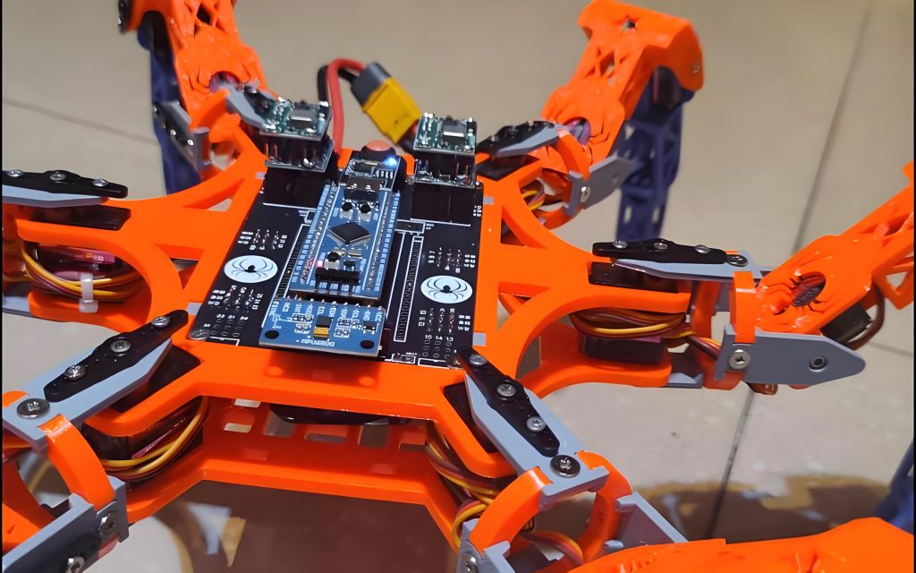
- منصات الروبوت التعليمية: لوحات التحكم الخاصة بالروبوتات التعليمية والمخبرية
- أنظمة التحكم في الطيران بدون طيار: تنظيم ومراقبة سرعة المحرك
- أتمتة المنزل الذكي: التحكم بمحرك المحرك للستائر الكهربائية والأقفال الذكية
- معدات التشغيل الآلي للمكاتب: التحكم في المحركات للطابعات وآلات التصوير
- معدات الاتصالات: التحكم في محرك مروحة التبريد للمحطات والمفاتيح الأساسية
تصنيف المنتج
يمكن تصنيف هذا المنتج علميًا عبر أبعاد متعددة وفقًا لمعايير لوحات الدوائر المطبوعة الدولية:
| البعد التصنيفي | فئة | المعيار الحاكم |
|---|---|---|
| نوع المادة الأساسية | لوحة مطبوعة صلبة FR-4 | IPC-4101E/21 |
| عدد الطبقات الموصلة | لوحة على الوجهين (2-طبقة) | IPC-6012E |
| عبر النوع | مطلي من خلال هول (PTH) لوحة على الوجهين | IPC-6012E |
| تثبيط اللهب | أول 94 V-0 تصنيف | أول 94 |
| الانتهاء من السطح | OSP (المواد الحافظة العضوية القابلة للحام) | إيبك-4555 |
| مجال التطبيق | الروبوتات/التحكم الصناعي ثنائي الفينيل متعدد الكلور | — |
مصدر البيانات: تعتمد معايير التصنيف على IPC-4101E, IPC-6012E, إيبك-4555, و ماي 94 المواصفات العالمية.
المواد المستخدمة
المادة الأساسية – KB6160A صفائح من نسيج زجاج الإيبوكسي المغطى بالنحاس
KB6160A ينتمي إلىFR-4 نسيج زجاجي إيبوكسي مغطى بالنحاس عائلة. تركيبته المادية تشمل:
- تعزيز: نسيج زجاجي إلكتروني من الدرجة الإلكترونية
- الموثق: راتنجات الايبوكسي المقاومة للهب
- احباط النحاس: المودعة كهربائيا (الضعف الجنسي) نحاس, 35 ميكرومتر (1 أوقية) سماكة
- نظام مثبطات اللهب: أول 94 V-0 إضافات مثبطات اللهب المتوافقة
تشطيب السطح – OSP (المواد الحافظة العضوية القابلة للحام)
OSP عبارة عن طلاء عضوي رقيق يتم تطبيقه على الأسطح النحاسية العارية. يمنع أكسدة النحاس ويحافظ على قابلية اللحام. وفقا ل IPC-4555, العمر الافتراضي لطلاءات OSP هوستة أشهر على الأقل.
مزايا الانتهاء من سطح OSP:
- فعالة من حيث التكلفة: أكثر اقتصادا من ENIG (الذهب الغمر بالنيكل غير الكهربائي) أو هاسل (تسوية لحام الهواء الساخن)
- صديقة للبيئة: متوافق تمامًا مع عمليات اللحام الخالية من الرصاص
- قابلية لحام جيدة: مناسبة للمنتجات ذات دورات حياة قصيرة إلى متوسطة أو البيئات الحميدة
قناع اللحام والأسطورة
- قناع اللحام: حبر أزرق يوفر حماية عازلة ويمنع سد اللحام
- أسطورة: حبر أبيض لتحديد المكونات وتوجيه التجميع
ملخص معلمات الأداء
| المعلمة | مواصفة |
|---|---|
| نوع صفح | KB6160A (كينج بورد FR-4) |
| سمك المجلس | 1.6 مم |
| عدد الطبقة | 2 طبقات (على الوجهين) |
| حجم اللوحة | 96.83 × 30.6 مم |
| الحد الأدنى للفتحة | 0.27 مم |
| الحد الأدنى لعرض التتبع | 0.32 مم |
| الحد الأدنى لتباعد التتبع | 0.382 مم |
| سمك رقائق النحاس | 35/35 ميكرومتر (1 أوز كلا الجانبين) |
| الانتهاء من السطح | مضادات الأكسدة OSP |
| لون قناع اللحام | أزرق |
| لون الأسطورة | أبيض |
| تيراغرام (درجة حرارة انتقال الزجاج) | ≥130 درجة مئوية (نموذجي 135 درجة مئوية) |
| تصنيف اللهب | أول 94 V-0 |
| الإجهاد الحراري (288℃) | ≥10 ثانية (نموذجي ≥180 ثانية) |
الميزات الهيكلية
- التوجيه على الوجهين: تحمل كل من الطبقات العلوية والسفلية دوائر, زيادة كثافة التوجيه بشكل فعال
- مطلي من خلال ثقب (PTH) تصميم: تمكين الربط الكهربائي بين الطبقات
- حماية سطح OSP: تضمن حماية أكسدة سطح النحاس موثوقية اللحام
- قناع لحام أزرق مع أسطورة بيضاء: يسهل التباين البصري الواضح عملية التجميع والفحص
- 1.6 مم سمك اللوحة القياسية: يوازن بين القوة الميكانيكية والتصنيع الموحد
عملية التصنيع
تقوم شركة UGPCB بتصنيعالتحكم في محرك الروبوت ثنائي الفينيل متعدد الكلور من خلال تدفق العملية الموحدة:
- قطع المواد: يتم قطع الألواح الكبيرة المكسوة بالنحاس KB6160A لتناسب أحجام لوحات الإنتاج
- حفر: CNC الحفر بالتحكم العددي يحقق 0.27 ملم الحد الأدنى للفتحة
- طلاء النحاس / الألواح بدون كهرباء: ترسيب النحاس الكيميائي متبوعًا بالطلاء الكهربائي للوحة لتمعدن الثقب
- نقل نمط الطبقة الخارجية: التصفيح → التعرض → التطوير يخلق نمط الدائرة
- طلاء النمط: مقاومة النحاس والقصدير والرصاص مطلية بالكهرباء على نمط الدائرة
- النقش: تتم إزالة رقائق النحاس المكشوفة لتشكيل الدوائر النهائية
- تجريد القصدير: تتم إزالة مقاومة الرصاص والقصدير
- المعالجة السطحية OSP: يتم تطبيق المواد الحافظة العضوية القابلة للحام OSP وفقًا لـ IPC-4555
- طباعة قناع اللحام: يتم تطبيق حبر قناع اللحام الأزرق, مُعرض ل, والمتطورة
- طباعة الأسطورة: شخصيات التعريف البيضاء مطبوعة بالشاشة الحريرية
- توجيه الملف الشخصي: يشكل توجيه CNC الشكل النهائي 96.83 × 30.6 أبعاد ملم
- الاختبارات الكهربائية: يتحقق المسبار الطائر أو الاختبار الشامل من الظروف المفتوحة/القصيرة
- التفتيش النهائي: الفحص البصري والأبعاد وفقًا لـ IPC-A-600K
- التعبئة والتغليف والشحن: التعبئة والتغليف فراغ مع حاجز الرطوبة
سيناريوهات التطبيق
سيناريو 1: التحكم بمحرك سيرفو للروبوت الصناعي
في الروبوتات الصناعية ذات ستة محاور, هذاثنائي الفينيل متعدد الكلور بمثابة لوحة تحكم للسائق المؤازر. يتلقى أوامر الحركة من الكمبيوتر المضيف. تنتقل إشارات التحكم PWM عبرها 0.32 ملم يتتبع مراحل تشغيل IGBT أو MOSFET, تحقيق عزم دوران دقيق والتحكم في سرعة المحركات المؤازرة.
سيناريو 2: محرك هيكل روبوت الخدمة
في روبوتات التوصيل ومركبات AGV (المركبات الموجهة الآلية), هذالوحة الدائرة يعمل بمثابة جوهر للتحكم في محرك مزدوج مستقل. إنه يتحكم بشكل مستقل في سرعات عجلة القيادة والتوجيه اليسرى واليمنى, تمكين السفر في خط مستقيم والتناوب في المكان.
سيناريو 3: منصات تطوير الروبوت التعليمي
في مختبرات الروبوتات الجامعية ومساحات التصنيع, هذاروبوت للتحكم في محرك ثنائي الفينيل متعدد الكلور بمثابة اللوحة الأساسية لأنظمة التحكم الروبوتية. وهو يدعم تطوير الطلاب والتحقق من خوارزميات محرك السيارات بما في ذلك FOC (التحكم الميداني) وتنظيم سرعة PID.
سيناريو 4: التحكم في سرعة محرك الطائرات بدون طيار
في كوادكوبتر, يمكن أن يعمل ثنائي الفينيل متعدد الكلور هذا كـ ESC (تحكم السرعة الإلكترونية) لوحة التحكم. يقوم بتحويل أوامر وحدة التحكم في الطيران إلى إشارات محرك المحرك, تحقيق التحكم في الاستجابة عالية السرعة للمحركات بدون فرش.
لماذا تختار PCB للتحكم في محرك الروبوت من UGPCB?
- الامتثال الكامل للمعايير الدولية: تم تصميم المنتجات وتصنيعها وفقًا لمعايير IPC-4101E/21, IPC-6012E, IPC-A-600K, إيبك-4555, و ماي 94 V-0
- ضمان المواد المتميزة: صفح Kingboard KB6160A FR-4 بطبقة Tg ≥130 درجة مئوية, أول 94 V-0 تصنيف اللهب, و ≥180 ثانية مقاومة الإجهاد الحراري
- تصنيع عالي الدقة: 0.27 ملم الحد الأدنى للفتحة و 0.32 الحد الأدنى لعرض التتبع مم يلبي متطلبات التوجيه عالي الكثافة
- خدمة وقفة واحدة: دعم كامل السلسلة بدءًا من تحسين تصميم PCB ومصادر المكونات وحتى تجميع SMT/DIP والاختبار الوظيفي
- 10+ سنوات من الخبرة في الصناعة: يخدم أكثر 3,000 عملاء المؤسسات على مستوى العالم
UGPCB هي شركة رائدة عالميًا في مجال تصميم ثنائي الفينيل متعدد الكلور, تصنيع, وخدمات تجميع PCBA. تأسست في 2014, تلتزم الشركة بتوفير حلول PCB عالية الدقة والموثوقة للغاية للعملاء في جميع أنحاء العالم.
احصل على عرض أسعار وعينات اليوم
UGPCB يدعم الخاص بكالتحكم في محرك الروبوت ثنائي الفينيل متعدد الكلور المشروع مع:
- ✅ سوق دبي المالي مجاني (تصميم للتصنيع) التقارير
- ✅ النماذج الأولية السريعة مع 24-ساعة التسليم متاح
- ✅حجم الإنتاج مع 20%+ معدلات عائد أعلى من متوسط الصناعة
- ✅ فريق هندسي محترف يقدم الدعم الفني
📧اتصل بنا للحصول على عرض أسعار مجاني: قم بزيارة موقع UGPCB لإرسال ملفات Gerber وBOM الخاصة بك. احصل على عرض أسعار آلي رائد في الصناعة.
📞الخط الساخن: تواصل معنا من خلال الدردشة عبر الإنترنت أو البريد الإلكتروني على موقعنا.
إعلان مصدر البيانات
جميع البيانات الفنية والمعلومات القياسية المذكورة في هذه المقالة تأتي من المصادر الرسمية التالية:
- Kingboard Laminates Holdings Ltd. - الوثائق الفنية للمنتج KB-6160A (المعلومات الفنية كيلو بايت)
- IPC (جمعية ربط الصناعات الإلكترونية) — مواصفات IPC-4101E/21 للمواد الأساسية للألواح المطبوعة الصلبة والمتعددة الطبقات, IPC-6012E مواصفات التأهيل والأداء للوحات المطبوعة الصلبة, IPC-A-600K قبول اللوحات المطبوعة, IPC-4555 مواصفات الأداء للمواد الحافظة العضوية القابلة للحام بدرجة الحرارة العالية (OSP) للوحات المطبوعة, دليل طرق الاختبار IPC-TM-650, IPC-2221 المعيار العام لتصميم اللوحة المطبوعة
- أول (مختبرات الضامنين) - أول 94 معيار اختبارات القابلية للاشتعال للمواد البلاستيكية لأجزاء الأجهزة والأجهزة
- قاعدة بيانات المواد PCBWay - KB-6160/6160A/6160C المعلمات الفنية
- الوثائق الفنية لـ OSHPark - ورقة مواصفات الركيزة KB6160A
تنصل: القيم النموذجية أعلاه هي بيانات الاختبارات المعملية المقدمة كمرجع فقط. قد يختلف الأداء الفعلي للمنتج وفقًا لعمليات التصنيع وبيئات التطبيق.













