

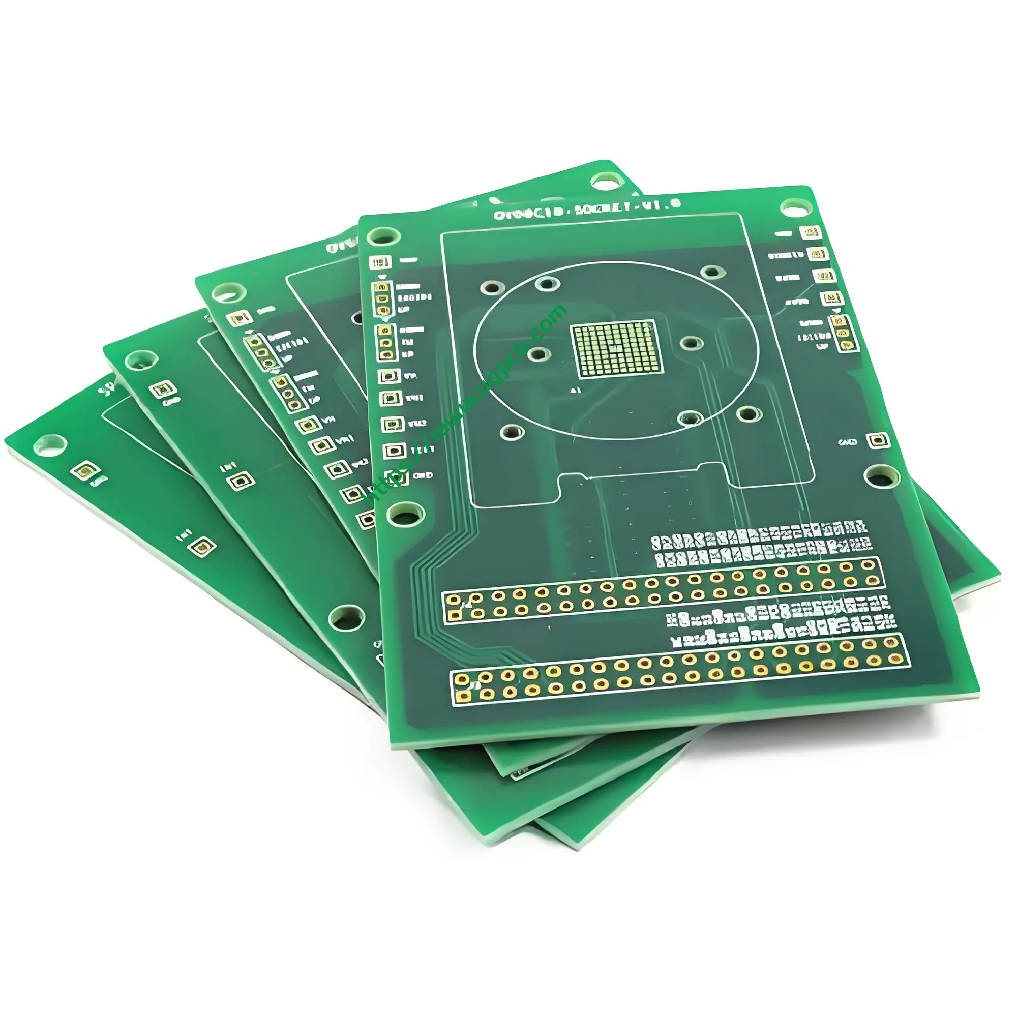
1. نظرة عامة على المنتج: ما هي المكنسة الكهربائية اللاسلكية ثنائي الفينيل متعدد الكلور?
مكنسة كهربائية لاسلكية ثنائي الفينيل متعدد الكلور (لوحة الدوائر المطبوعة) هو المكون الإلكتروني الأساسي المسؤول عن التحكم في قيادة المحرك, إدارة الطاقة, تفاعل المستخدم, وحماية السلامة داخل المكنسة الكهربائية اللاسلكية. بعبارات بسيطة, فهو بمثابة "الدماغ" و"المركز العصبي" للجهاز. يتلقى أوامر الزر, يتحكم في سرعة المحرك بدون فرش, يدير شحن البطارية وتفريغها, يراقب حالة التشغيل, وينفذ وسائل حماية السلامة المتعددة.
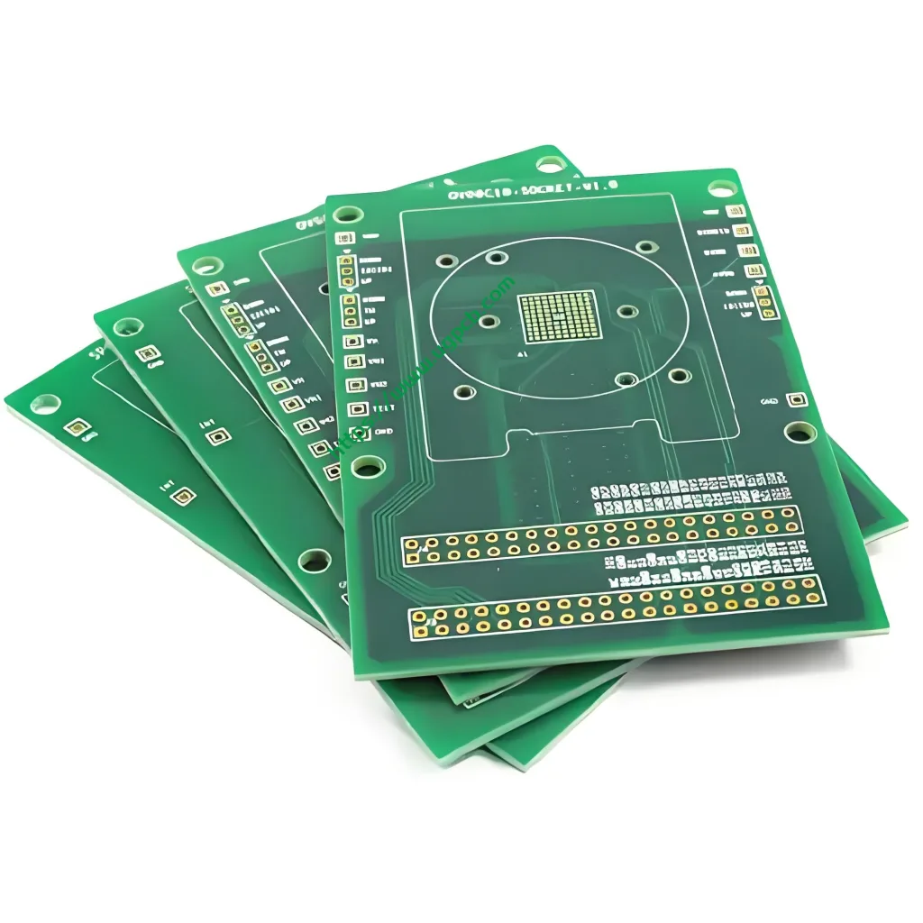
تقدم UGPCB هذه المكنسة الكهربائية اللاسلكية PCB - أ 2-طبقة لوحة الدوائر المطبوعة الصلبة مصممة خصيصًا لمعدات التنظيف المحمولة. يستخدم صفائح نحاسية من الإيبوكسي الزجاجي FR-4 كمادة أساسية. سمك اللوح 1.0 ملم, والأبعاد هي 86.37 × 72.6 ملم. يتناسب هذا الحجم الصغير تمامًا مع المساحات الداخلية الضيقة للمكانس اللاسلكية المحمولة باليد أو ذات النمط العصا.
لكل IPC-6012F مواصفات التأهيل والأداء للألواح المطبوعة الصلبة, هذا المنتج يندرج تحت لوحة مطبوعة صلبة على الوجهين (مع ثقوب مطلية) فئة. كجزء أساسي من محطة UGPCB الشاملة ثنائي الفينيل متعدد الكلور الحلول, يلبي هذا المنتج معايير IPC الدولية بدءًا من التصميم وحتى التصنيع ومراقبة الجودة. إنه يوفر لمصنعي المكانس الكهربائية موثوقية عالية, فعالة من حيث التكلفة ثنائي الفينيل متعدد الكلور حل.
2. تصنيف المنتج: تحديد المواقع العلمية وتصنيف الصناعة
لكل IPC-6012F و ثنائي الفينيل متعدد الكلور القياسي أنظمة تصنيف الصناعة, يمكن تصنيف هذا المنتج علميا على النحو التالي:
| البعد التصنيفي | فئة |
|---|---|
| حسب الهيكل | لوحة مطبوعة صلبة على الوجهين (مع ثقوب مطلية) |
| بواسطة المواد الأساسية | FR-4 صفائح زجاجية منسوجة من النحاس ومغطاة بالنحاس (متوافق مع IPC-4101) |
| حسب عدد الطبقات | 2-لوحة الطبقة (ثنائي الفينيل متعدد الكلور على الوجهين) |
| بواسطة الانتهاء من السطح | HASL خالي من الرصاص (تسوية لحام الهواء الساخن) |
| حسب تصنيف القابلية للاشتعال | أول 94 V-0 |
| عن طريق التطبيق | الالكترونيات الاستهلاكية / لوحة تحكم للأجهزة الصغيرة (المكنسة الكهربائية PCBA) |
ضمن صناعة الإلكترونيات المكانس الكهربائية, هذا المنتج ينتمي إلىمحرك السيارات والتحكم PCBA فئة. جنبا إلى جنب مع لوحة التحكم الرئيسية ولوحة إدارة الطاقة, إنها تشكل وحدات الدائرة الأساسية الثلاثة للمكنسة الكهربائية اللاسلكية.
3. المعلمات التقنية الرئيسية
3.1 المادة الأساسية وسمك اللوحة
- المواد الأساسية: فر-4 (صفائح من النحاس والإيبوكسي المقوى بالألياف الزجاجية)
- سمك المجلس: 1.0مم
FR-4 هو الركيزة الصلبة الأكثر استخدامًا على نطاق واسع في صناعة ثنائي الفينيل متعدد الكلور. لIPC-4101, يوفر FR-4 عزلًا كهربائيًا ممتازًا, القوة الميكانيكية, ومقاومة الحرارة. يحتوي معيار FR-4 على درجة حرارة التزجج (تيراغرام) من 130-140 درجة مئوية. ل IPC-6012, نطاق التسامح لسمك اللوحة 1.0 مم هو ± 0.1 مم.
3.2 عدد الطبقات وأبعادها
- عدد الطبقة: 2 طبقات (لوحة على الوجهين)
- أبعاد: 86.37 × 72.6 مم
يتحكم الهيكل المكون من طبقتين في تكلفة التصنيع بشكل فعال مع توفير أداء كهربائي قوي. وهذا يجعلها الاختيار السائد للوحات التحكم في المكنسة الكهربائية اللاسلكية. الاتفاق 86.37 × تم تحسين أبعاد 72.6 مم للمساحة المحدودة داخل المكانس الكهربائية.
3.3 عرض التتبع/التباعد والحد الأدنى لحجم الثقب
- الحد الأدنى لحجم الفتحة: 0.45مم
- تتبع العرض/التباعد: 0.45مم / 0.391مم
لكل IPC-2221Cالمعيار العام لتصميم اللوحة المطبوعة, يجب أن يأخذ تصميم عرض التتبع والتباعد في الاعتبار الأداء الكهربائي, القدرة الاستيعابية الحالية, والقدرة على التصنيع. يدعم الحد الأدنى لحجم الثقب 0.45 مم اللحام الموثوق به لمكونات DIP التقليدية والأجزاء من خلال الفتحة.
للقدرة الاستيعابية الحالية, الصيغة القياسية للصناعةأنا = ك·ΔT^0.44·A^0.725 (حيث A هي مساحة المقطع العرضي) يظهر أنه مع 1 أوقية من النحاس, 0.45 ملم (تقريبا. 18ميل) يمكن أن يحمل التتبع حوالي 1.8-2.0 أمبير. تستخدم المكنسة الكهربائية اللاسلكية PCB عرض التتبع هذا لإشارات محرك المحرك وإشارات التحكم, ضمان عملية مستقرة على المدى الطويل.
3.4 سمك رقائق النحاس
- سمك رقائق النحاس: 1/1 أوقية (1 أونصة على كلا الطبقتين الخارجيتين)
1احباط النحاس أوقية (تقريبا. 35ميكرومتر) هو التكوين القياسي لثنائي الفينيل متعدد الكلور للإلكترونيات الاستهلاكية. إنه يحقق توازنًا ممتازًا بين القدرة الاستيعابية الحالية, الموصلية الحرارية, والتكلفة.
3.5 الانتهاء من السطح
- الانتهاء من السطح: HASL خالي من الرصاص (تسوية لحام الهواء الساخن)
HASL عبارة عن تشطيب سطحي ثنائي الفينيل متعدد الكلور ناضج واقتصادي. HASL الخالي من الرصاص يلبي المتطلبات البيئية لـ RoHS. وفقًا لمعايير IPC, عادةً ما يكون سمك HASL الخالي من الرصاص من 1 إلى 40 ميكرومتر, مع العمليات التقليدية التي يتم التحكم فيها عند 5-25 ميكرومتر. توفر هذه النهاية قابلية لحام ممتازة (قابلية التبلل) وعمر تخزين جيد يصل إلى 12 شهور.
3.6 قناع اللحام والأسطورة
- لون قناع اللحام: الحبر الأخضر
- لون الأسطورة: أبيض
قناع اللحام الأخضر هو الخيار الأكثر شعبية في الصناعة. يوفر حماية عزل ممتازة وتباين عالي الهيئة العربية للتصنيع (الفحص البصري الآلي). الأساطير البيضاء واضحة وسهلة القراءة, تسهيل وضع المكونات والصيانة المستقبلية.
4. إرشادات التصميم: اتباع معايير IPC-2221C
يجب أن تتبع المكنسة الكهربائية اللاسلكية PCB المصممة جيدًا هذه المبادئ الأساسية (لكل IPC-2221C):
4.1 تصميم الأداء الكهربائي
- عرض تتبع الطاقة: احسب باستخدام الصيغة أنا = ك·ΔT^0.44·A^0.725 لضمان بقاء ارتفاع درجة الحرارة أقل من 10 درجات مئوية عند أقصى تيار تشغيل.
- سلامة الإشارة: استخدم عرض تتبع 0.45 مم لإشارات التحكم لضمان النقل الكامل لإشارات التحكم في سرعة PWM وإشارات المستشعر.
- تصميم التأريض: استخدم استراتيجيات التأريض أحادية النقطة أو التأريض المنفصل لمنع تداخل حلقة الطاقة مع حلقة التحكم.
4.2 تصميم الإدارة الحرارية
تولد المكانس الكهربائية اللاسلكية حرارة كبيرة من الدوائر المتكاملة منخفضة المقاومة (MOSFET) أثناء التشغيل. ال تصميم ثنائي الفينيل متعدد الكلور يجب معالجة هذا من خلال:
- وضع الحرارة عبر المصفوفات تحت أجهزة الطاقة.
- توسيع آثار التيار العالي أو إضافة النحاس المكشوف لتبديد الحرارة بشكل أفضل.
- استخدام سمك لوح 1.0 مم لموازنة التوصيل الحراري والقوة الميكانيكية.
4.3 تصميم الهيكل الميكانيكي
ال 86.37 × يجب أن تتطابق أبعاد 72.6 ملم بدقة مع هيكل المكنسة الكهربائية. يجب أن تتوافق مواضع فتحات التثبيت ومواقع الموصلات مع متطلبات التصميم الهيكلي. يدعم الحد الأدنى لحجم الثقب 0.45 مم اللحام عبر الفتحة لمختلف مكونات وموصلات DIP.
5. مبدأ العمل
تعمل المكنسة الكهربائية اللاسلكية PCB من خلال العمليات الأساسية التالية:
① مدخلات الطاقة وإدارتها: حزمة بطارية الليثيوم (عادة 21.6 فولت أو 25.2 فولت) يمر عبر دائرة إدارة الطاقة على PCB. وهذا يوفر جهدًا ثابتًا لشريحة التحكم الرئيسية ودوائر التشغيل.
② حساب شريحة التحكم الرئيسية: MCU (متحكم) على PCB يتلقى أوامر الزر. يقوم بحساب وإخراج إشارات القيادة ثلاثية الطور باستخدام FOC (التحكم الميداني) أو خوارزميات التحكم في الموجة المربعة.
③ محرك السيارات: يتم تضخيم إشارات المحرك بواسطة أجهزة الطاقة MOSFET. تقوم هذه الإشارات بعد ذلك بتشغيل محرك DC بدون فرش (بلدك) لتدور بسرعة عالية, توليد تدفق الهواء اللازم للشفط.
④ ردود الفعل والحماية: يقوم PCB بمراقبة تيار المحرك بشكل مستمر, جهد البطارية, درجة حرارة, وغيرها من المعلمات. عندما يكتشف حالات غير طبيعية مثل التيار الزائد, على درجة الحرارة, انخفاض الجهد, أو قفل الدوار, يقوم بتنفيذ إجراءات الحماية على الفور.
6. المواد المستخدمة
| عنصر | مادة | وصف |
|---|---|---|
| الركيزة | FR-4 زجاج إيبوكسي | متوافق مع IPC-4101 |
| طبقة موصلة | رقائق النحاس كهربائيا (1أوقية) | 1أوقية على كلا الطبقتين الخارجيتين |
| قناع اللحام | حبر أخضر قابل للصور | حماية العزل, مقاومة الأكسدة |
| الانتهاء من السطح | سبيكة HASL خالية من الرصاص | متوافق مع RoHS |
| حبر الأسطورة | حبر إيبوكسي أبيض | التباين العالي, مقاومة للحرارة |
الركيزة FR-4 تحمل UL 94 V-0 تصنيف القابلية للاشتعال. في اختبار الحرق العمودي, اللهب ينطفئ في الداخل 10 ثواني بعد الإزالة, مع عدم وجود قطرات حرق. هذه الميزة ضرورية للطاقة العالية, الأجهزة التي تعمل بالبطارية مثل المكانس الكهربائية اللاسلكية. إنه يقلل بشكل كبير من خطر نشوب حريق بسبب أعطال الدائرة.
7. مواصفات الأداء
7.1 الأداء الكهربائي
| المعلمة | مواصفة | المعيار المرجعي |
|---|---|---|
| مقاومة العزل | ≥10^6 مΩ | IPC-6012F |
| عازلة تحمل الجهد | ما يصل إلى 500 فولت (تعتمد على التصميم) | IPC-2221C |
| مقاومة التوصيل | ≥50mΩ (عادي) | IPC-6012F |
| الممانعة المميزة | يمكن التحكم بها عند الطلب (50أوم / 90 أوم / 100 أوم) | IPC-2221C |
7.2 الأداء الحراري
| المعلمة | مواصفة | المعيار المرجعي |
|---|---|---|
| درجة حرارة انتقال الزجاج (تيراغرام) | ≥135 درجة مئوية (طريقة كالوريمتر المسح الضوئي التفاضلي (DSC).) | IPC-TM-650 2.4.25 |
| مقاومة حرارة اللحام | 288درجة مئوية / 10ق, لا delamination | إيبك-4101 |
| المحور Z CTE (CTEz) | ≥65 جزء في المليون/درجة مئوية (50-260 درجة مئوية) | إيبك-4101 |
7.3 الأداء الميكانيكي
| المعلمة | مواصفة | المعيار المرجعي |
|---|---|---|
| التسامح سمك المجلس | ± 0.1 ملم | IPC-6012 |
| التسامح مع حجم الثقب | ± 0.05 ملم | IPC-6012F |
| تصنيف القابلية للاشتعال | أول 94 V-0 | أول 94 |
7.4 مصداقية
- اختبار قابلية اللحام: متوافق مع IPC-J-STD-003
- اختبار الشيخوخة: 500 ساعات تحت ظروف مزدوجة 85 (85درجة مئوية / 85%ر.س) مع عدم وجود تشوهات
8. الميزات الهيكلية
8.1 2-مزايا لوحة الطبقة
تحمل الطبقة العليا المكونات الرئيسية وآثار الإشارة. تتعامل الطبقة السفلية مع المكونات المساعدة وصب النحاس الأرضي/الطاقي. يحقق التصميم المكون من طبقتينأفضل تكلفة وأعلى موثوقية توازن وظائف التحكم في المكنسة الكهربائية اللاسلكية.
8.2 مطلي من خلال هول (PTH) عملية
تستخدم جميع الثقوب عبر عملية الفتحة المطلية. وهذا يضمن اتصالًا موثوقًا به بين الطبقات العلوية والسفلية. كما أنه يوفر دعمًا ميكانيكيًا قويًا واتصالًا كهربائيًا لمكونات DIP.
8.3 عملية جسر قناع اللحام
يشكل قناع اللحام الأخضر جسورًا بين الوسادات المتجاورة. وهذا يمنع حدوث شورتات لحام ويحسن إنتاجية وضع SMT.
9. تدفق عملية التصنيع
يتبع UGPCB معايير IPC-6012F بدقة للتحكم في كل خطوة إنتاج:
① فحص المواد الواردة →② إنشاء دائرة الطبقة الداخلية (للوحات ذات طبقتين, هذه هي الطبقة الخارجية مباشرة) →③ التصفيح (لا ينطبق على الألواح المكونة من طبقتين) →④ الحفر (الحد الأدنى لحجم الثقب 0.45 ملم) →⑤ ترسيب النحاس اللاكهربائي / طلاء اللوحة →⑥ دائرة الطبقة الخارجية →⑦ طلاء النمط →⑧ النقش →⑨ قناع اللحام (الحبر الأخضر) →⑩ تشطيب السطح (HASL خالية من الرصاص) →⑪ أسطورة (شخصيات بيضاء) →⑫ توجيه الملف الشخصي (86.37 × 72.6 ملم) →⑬ الاختبار الكهربائي →⑭ التفتيش النهائي (لـ IPC-A-600) →⑮ التعبئة والتغليف والشحن
تخضع كل دفعةاختبار مسبار الطيران أواختبار تركيبات مخصصة لضمان 100% لا دوائر مفتوحة أو قصيرة.
10. سيناريوهات التطبيق
10.1 التطبيقات الأولية
- مكانس لاسلكية محمولة: قيادة المحرك والتحكم في المساحات المدمجة
- مكانس لاسلكية على شكل عصا: إدارة البطارية ومحرك بدون فرش
- المكانس الروبوتية: التحكم في الملاحة وقيادة السيارات
- مكانس السيارة: 12التكيف والتحكم في الطاقة V/24V
- أجهزة التنظيف الذكية: اتصال إنترنت الأشياء والتحكم الذكي
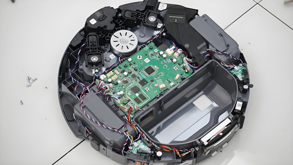
10.2 أمثلة على المنتج النهائي
يمكن استخدام ثنائي الفينيل متعدد الكلور على نطاق واسع في لوحات التحكم ولوحات التشغيل للمكانس الكهربائية اللاسلكية وأجهزة التنظيف المماثلة من العلامات التجارية مثل Xiaomi, دايسون, تينيكو, و ليفهيت.
11. لماذا تختار المكنسة الكهربائية اللاسلكية PCB من UGPCB?
✅الامتثال للمعايير الدولية: تصميم, تصنيع, والتفتيش يتوافق تمامًا مع IPC-6012F, إيبك-أ-600, IPC-2221C, وغيرها من المعايير الدولية
✅يو ال 94 فولت-0 السلامة من الحرائق: تحقق الركيزة FR-4 أعلى معدل حرق عمودي, ضمان سلامة الجهاز

✅عملية صديقة للبيئة خالية من الرصاص: تشطيب سطح HASL الخالي من الرصاص يتوافق مع توجيهات RoHS وREACH البيئية
✅قدرة تصنيع مثبتة: يوفر UGPCB خدمات شاملة بدءًا من تصميم ثنائي الفينيل متعدد الكلور وتصنيعه وحتى تجميع PCBA
✅رقابة صارمة على الجودة: الفحص البصري لكل IPC-A-600 و 100% الاختبارات الكهربائية تضمن جودة الشحن
✅الأبعاد المحسنة المدمجة: ال 86.37 × مقاس 72.6 ملم يناسب تمامًا المساحة الداخلية لمختلف المكانس الكهربائية اللاسلكية
12. احصل على عرض أسعار وعينات اليوم
UGPCB ملتزمة بتوفير دقة عالية, حلول PCB وPCBA عالية الموثوقية لمصنعي الإلكترونيات في جميع أنحاء العالم. سواء كنت بحاجة مركبات ثنائي الفينيل متعدد الكلور العارية, PCBA مجمعة بالكامل, أو خدمات وقفة واحدة من التصميم إلى الإنتاج الضخم, لدى UGPCB الخبرة اللازمة لدعمك.
📧اتصل بـ UGPCB للحصول على عرض أسعار مخصص اليوم →
- موقع إلكتروني: www.ugpcb.com
- تعديلات التصميم المخصص والتحسينات المتاحة
- سوق دبي المالي مجاني (تصميم للتصنيع) مراجعة
- يتوفر كل من النماذج الأولية السريعة والإنتاج بكميات كبيرة
إعلان مصدر البيانات
المعايير الفنية والبيانات المذكورة في هذه المقالة تأتي من المنظمات الموثوقة التالية:
- IPC (جمعية ربط الصناعات الإلكترونية): IPC-6012F مواصفات التأهيل والأداء للألواح المطبوعة الصلبة, إيبك-أ-600 قبول اللوحات المطبوعة, IPC-2221C المعيار العام لتصميم اللوحة المطبوعة, إيبك-4101 مواصفات المواد الأساسية للوحات المطبوعة الصلبة ومتعددة الطبقات, IPC-TM-650 دليل طرق الاختبار
- أول (مختبرات الضامنين): أول 94 معيار السلامة من قابلية اشتعال المواد البلاستيكية لأجزاء الأجهزة والأجهزة – خامسا-0 تصنيف
- الصيغة الهندسية القياسية الصناعية: صيغة القدرة الاستيعابية الحالية لثنائي الفينيل متعدد الكلور أنا = ك·ΔT^0.44·A^0.725













