

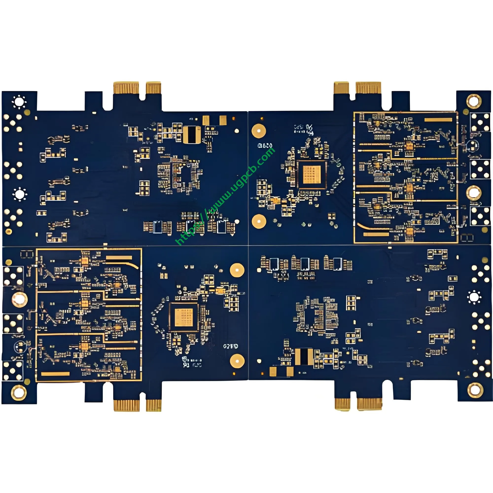
Panoramica del prodotto: Che cos'è un PCB del disco rigido meccanico del computer?
Un disco rigido meccanico del computer PCB (Circuito stampato) è il componente di controllo elettrico più critico all'interno di un'unità disco rigido (HDD). Questa scheda trasporta il chip del controller principale, memoria cache, Circuiti di gestione dell'alimentazione, e vari connettori di interfaccia. Coordina le operazioni di lettura/scrittura della testina, controllo del motore del mandrino, e comunicazione di dati tra l'host e il supporto di memorizzazione.
UGPCB lo presentaPCB del disco rigido meccanico del computer prodotto con standard di settore Materiale in fibra di vetro FR4. La tavola misura 1,6 mm di spessore con un fronte-retro (2-strato) progetto. Le sue dimensioni precise sono 53.68 x 42,7 mm, progettato specificamente per dispositivi di archiviazione con disco rigido meccanico da 3,5 pollici. Come il “centro neurale” del disco rigido, la qualità e le prestazioni di questo PCB determinano direttamente la velocità di trasferimento dei dati, stabilità in lettura/scrittura, e la durata complessiva.
Nel mondo odierno basato sui dati, i dischi rigidi meccanici mantengono una posizione insostituibile nei data center, personal computer, sorveglianza di sicurezza, e archiviazione nel cloud grazie alla loro grande capacità e al basso costo per gigabyte. Come componente principale degli HDD, ILcircuito stampato del disco rigido richiede qualità e affidabilità eccezionali.
Definizione del prodotto e classificazione scientifica
Definizione del prodotto
UNPCB del disco rigido meccanico del computer è un circuito stampato rigido progettato specificamente per l'uso interno all'interno di unità disco rigido meccaniche (HDD). Trasporta il controller principale, memoria cache, Circuiti di gestione dell'alimentazione, e connettori di interfaccia per abilitare il controllo di lettura/scrittura dei dati, azionamento del motore, e comunicazione con l'ospite.
Classificazione scientifica
Secondo IPC-6012FSpecifiche di qualificazione e prestazione per circuiti stampati rigidi, questo prodotto rientra nelle seguenti categorie di classificazione scientifica:
| Dimensione Classificazione | Categoria |
|---|---|
| Per struttura | Cartoncino stampato fronte-retro rigido |
| Per conteggio strati | 2-Scheda a strati (2L) |
| Per tipo | Con fori passanti (PTH) |
| Per substrato | Fibra di vetro epossidica FR4 |
| Per grado di infiammabilità | UL 94 V-0 (Grado di ritardante di fiamma più elevato) |
| Per finitura superficiale | Placcatura in oro |
| Per classe di prestazione IPC | Classe 2 (Prodotti elettronici di servizio dedicati) |
Secondo IPC-6012F, questo prodotto è unCartoncino stampato fronte-retro rigido con fori passanti placcati. Soddisfa la classe IPC 2 requisiti per le apparecchiature elettroniche di servizio dedicate, garantendo affidabilità durante il funzionamento continuo dell'HDD, variazioni di temperatura, e interferenza elettromagnetica.
Specifiche di progettazione e parametri tecnici
Materiale del substrato: FR4 Fibra di vetro
Questo prodotto utilizza FR4 (Ritardante di fiamma 4) come materiale di base, il laminato rigido più utilizzato nell'industria dei PCB. FR4 è costituito da un legante in resina epossidica rinforzato con tessuto in fibra di vetro. I principali vantaggi includono:
- Resistenza meccanica superiore: Il rinforzo in fibra di vetro fornisce un'eccellente resistenza alla flessione e stabilità dimensionale
- Isolamento elettrico eccezionale: Resistività di volume elevata e costante dielettrica stabile
- UL 94 V-0 grado di infiammabilità: La fiamma si autoestingue all'interno 10 secondi dopo la rimozione della fiamma senza gocciolamenti
- Ottima resistenza termica: Tg (temperatura di transizione vetrosa) ≥135°C, compatibile con processi di saldatura senza piombo
Spessore del cartone e numero di strati: 1.6Design fronte-retro da mm
Spessore della scheda: 1.6mm – Questo rappresenta il “spessore dorato” nel settore PCB e la specifica più tipica per schede rigide a doppia faccia secondo IPC-6012. Lo spessore di 1,6 mm raggiunge un equilibrio ottimale tra resistenza meccanica, resistenza alla flessione, e costo di produzione.
Secondo IPC-6012F, la tolleranza dello spessore del pannello finito per uno spessore nominale di 1,6 mm è± 10%, ottenendo un intervallo accettabile di1.44mm a 1,76 mm.
Conteggio degli strati: 2 strati (2L) – Il design a doppia faccia soddisfa i requisiti di complessità di routing dei circuiti dei dischi rigidi ottenendo al tempo stesso un equilibrio ottimale tra costi e prestazioni. Sia gli strati superiori che quelli inferiori portano tracce, con fori passanti placcati (PTH) fornitura di collegamenti elettrici interstrato.
Specifiche dimensionali precise
Dimensioni del contorno: 53.68 x 42,7 mm
UGPCB personalizza con precisione queste dimensioni in base ai tradizionali standard di settore dei dischi rigidi meccanici da 3,5 pollici, garantendo la compatibilità fisica con il contenitore del disco, motore del mandrino, e il gruppo del braccio dell'attuatore. La lunghezza di 53,68 mm e la larghezza di 42,7 mm sfruttano appieno lo spazio interno limitato del disco rigido massimizzando al tempo stesso l'area del circuito funzionale.
Parametri di routing di precisione
Diametro del foro minimo: 0.22mm
Il diametro minimo del foro di 0,22 mm rappresenta un requisito di precisione di perforazione meccanica relativamente elevato. Le proporzioni (spessore della scheda rispetto al diametro del foro) È1.6 / 0.22 ≈ 7.27:1, ben entro il limite superiore della perforazione meccanica convenzionale di ≤8:1. Ciò garantisce uno spessore uniforme della placcatura in rame e affidabilità sulle pareti dei fori.
Larghezza della linea / interlinea: 0.37 x 0,42 mm
Il routing di precisione con larghezza di linea di 0,37 mm e spaziatura di linea di 0,42 mm garantisce l'integrità del segnale fornendo allo stesso tempo spazio di routing sufficiente per bus dati ad alta velocità. Questa combinazione di parametri raggiunge un equilibrio ideale tra resa produttiva e prestazioni elettriche.
Spessore di lamina di rame: 35/35μm (1 oz)
Misurano sia i fogli di rame dello strato superiore che quello inferiore35μm (1 oz) , che rappresenta lo spessore tipico del rame del conduttore esterno per schede stampate rigide secondo IPC-6012F.
Secondo IPC-D-275, la capacità di trasporto di corrente del conduttore esterno viene calcolata come segue:
io = 0.0647 × (ΔT)^0,4281 × (UN)^0,6734
Dove:
- I = Portata massima di corrente (UN)
- ΔT = Aumento di temperatura consentito (° C.)
- A = Area della sezione trasversale del conduttore (mm²)
Per foglio di rame da 35μm con larghezza del tratto di 1 mm, la sezione trasversale del conduttore A = 0,035 mm². Con un aumento della temperatura di 10°C, questo conduttore può trasportare circa1.0UN.
Con una larghezza della linea di 0,37 mm, la corrispondente capacità di trasporto di corrente è di circa0.37UN (con un aumento della temperatura di 10°C), soddisfa pienamente i requisiti attuali delle linee di segnale e di alimentazione nei circuiti dei dischi rigidi.
Finitura superficiale: Placcatura in oro
Questo prodotto utilizzaPlaccatura in oro come finitura superficiale, con uno strato di nichel (2-3μm) depositato per primo, seguito da uno strato d'oro (≥0,025μm) sulle superfici dei cuscinetti.
Principali vantaggi della placcatura in oro:
- Eccezionale resistenza all'usura: Lo strato d'oro duro resiste a ripetuti cicli di accoppiamento
- Resistenza di contatto estremamente bassa: Garantisce una trasmissione del segnale stabile e affidabile
- Ottima saldabilità: La superficie dorata resiste all'ossidazione, consentendo un'elevata affidabilità di saldatura
- Stabilità di conservazione a lungo termine: Lo strato dorato protegge efficacemente le superfici in rame dall'ossidazione e dalla corrosione
Lo strato di nichel funge da barriera alla diffusione, prevenendo l'interdiffusione tra rame e oro ed evitando la formazione di composti intermetallici fragili rame-oro, garantire fondamentalmente l’affidabilità a lungo termine.
Maschera di saldatura e leggenda: Maschera Blu con Caratteri Bianchi
Colore della maschera di saldatura: Blu
La maschera di saldatura blu fornisce un'identificazione visiva distintiva offrendo allo stesso tempo un'eccellente protezione isolante e resistenza all'umidità. La maschera di saldatura copre tutte le aree di instradamento tranne i pad, prevenendo efficacemente ponti di saldatura e cortocircuiti durante l'assemblaggio.
Colore della legenda: Bianco
La stampa della leggenda bianca sulla maschera di saldatura blu crea un contrasto elevato. Designatori di riferimento dei componenti, segni di polarità, e le informazioni sulla versione rimangono chiaramente leggibili, facilitando notevolmente il posizionamento dell'SMT e la successiva ispezione e riparazione.
Principio di funzionamento: In che modo il PCB dell'HDD guida l'archiviazione dei dati?
Il PCB del disco rigido meccanico del computer funziona ai seguenti livelli:
Decodifica ed esecuzione dei comandi
Quando il computer invia comandi di lettura/scrittura al disco rigido, questi comandi vengono trasmessi attraverso l'interfaccia SATA al chip controller sul PCB. Il chip del controller decodifica i comandi e invia segnali di controllo attraverso le tracce PCB al driver dell'attuatore e al motore del mandrino.
Controllo lettura/scrittura dati
Il canale di lettura/scrittura sul PCB è costituito da un preamplificatore, circuiti di lettura/scrittura, e orologio di sincronizzazione. Durante le operazioni di lettura, i deboli segnali magnetici rilevati dalla testina di lettura/scrittura passano attraverso il preamplificatore e vengono convertiti dal canale di lettura/scrittura in segnali digitali, quindi trasmesso all'host tramite l'interfaccia. Le operazioni di scrittura seguono il percorso inverso.
Gestione dell'energia
Il modulo di gestione tensione/corrente sul PCB converte l'alimentazione +5 V e +12 V proveniente dall'host nelle varie tensioni richieste dai diversi componenti dell'HDD. Questo modulo implementa anche funzioni avanzate di gestione energetica, inclusa l'ottimizzazione energetica, modalità di sospensione automatica, e protezione hot-swap.
Cache dati e firmware
Il chip cache sul PCB memorizza temporaneamente i dati a cui si accede di frequente per migliorare le prestazioni di lettura/scrittura. Il chip firmware memorizza il microcodice operativo del disco rigido, controllo della logica di base, compreso il posizionamento della testa, cattiva gestione del settore, e monitoraggio SMART.
Specifiche prestazionali e standard di qualità
Prestazioni elettriche
| Parametro | Specifica | Norma di riferimento |
|---|---|---|
| Resistenza di isolamento | ≥10⁶ MΩ | IPC-6012F |
| Tensione di resistenza dielettrica | ≥500 VCA (1 minuto) | IPC-6012F |
| Resistenza del conduttore | ≤1,0 mΩ/cm | IPC-6012F |
| Impedenza caratteristica | Controllato in base al design | IPC-6012F |
Prestazioni meccaniche
| Parametro | Specifica | Norma di riferimento |
|---|---|---|
| Tolleranza sullo spessore del pannello | ± 10% (1.44–1,76 mm) | IPC-6012F |
| Spessore rame parete foro | ≥20μm (Classe 2) | IPC-6012F |
| Forza della pelatura | ≥1,1 N/mm | IPC-6012F |
| Punteggio di infiammabilità | UL 94 V-0 | UL 94 |
Ispezione visiva e dimensionale
Secondo IPC-A-600KAccettabilità dei circuiti stampati, i PCB finiti devono superare un rigoroso controllo visivo (3 ingrandimento diottrico, circa 1,75x) per garantire l'assenza di graffi, bolle, rame a vista, o altri difetti.
Processo di produzione e controllo qualità
Flusso di produzione standard
- Taglio: Laminato rivestito in rame FR4 tagliato a misura di pannello
- Perforazione: 0.22foratura meccanica di precisione mm
- Rame chimico / Placcatura del pannello: Deposizione chimica + galvanica a pannello intero
- Trasferimento del modello: Laminazione con film secco → esposizione → sviluppo → incisione
- Placcatura con motivo: Accumulo di strato di rame fino a 35μm
- Striscia / Acquaforte / Striscia: Formazione del modello di circuito finale
- Stampa della maschera di saldatura: Serigrafia maschera di saldatura blu + polimerizzazione
- Stampa della legenda: Serigrafia legenda bianca
- Placcatura in oro: Placcatura in nichel-oro sulle superfici dei cuscinetti
- Instradamento: Instradamento CNC a 53.68 x contorno 42,7 mm
- Prova elettrica: Sonda volante / test di apertura-corto del dispositivo
- Ispezione FQC: 100% controllo qualità finale secondo IPC-A-600K
Sistema di controllo qualità
UGPCB implementa rigorosamente la classe IPC-6012F 2 standard con controllo di qualità end-to-end dai materiali in entrata alla spedizione:
- Ispezione in arrivo: 100% ispezione laminati FR4, lamine di rame, inchiostri, e altre materie prime
- Controllo in-process: Checkpoint di qualità in ogni fase del processo con monitoraggio SPC
- Ispezione dell'AOI: 100% ispezione ottica automatica per difetti del circuito
- Test di affidabilità: Prove di shock termico, test di umidità, test di saldabilità
Scenari applicativi e valore di mercato
Scenari applicativi primari
| Area di applicazione | Caso d'uso specifico | Requisiti della PCB |
|---|---|---|
| Personal computer | HDD da tavolo, HDD esterno per laptop | Alta affidabilità, lunga durata |
| Centri dati | Server di archiviazione nel cloud, array di storage aziendali | 24/7 funzionamento continuo |
| Sorveglianza di sicurezza | Videoregistratori di rete NVR, server di archiviazione video | Scrittura continua ad alta capacità |
| Elettronica di consumo | Console di gioco, set-top box, televisori intelligenti | Ottimizzato in termini di costi, funzionamento stabile |
| Recupero dati | Sostituzione e riparazione PCB HDD difettoso | Compatibilità precisa, plug-and-play |

Prospettive di mercato
Secondo QYR (QYRicerca) statistiche, il mercato globale dei PCB per dischi rigidi meccanici mantiene una crescita costante. Sebbene le unità a stato solido (SSD) stanno rapidamente penetrando nel mercato dei consumatori, i dischi rigidi meccanici continuano a dominare nello storage ad alta capacità (8TBC e oltre), celle frigorifere del data center, e applicazioni di sorveglianza di sicurezza a causa della lorovantaggio sul costo per gigabyte Eaffidabilità della conservazione dei dati a lungo termine.
Perché scegliere il PCB del disco rigido meccanico per computer di UGPCB?
Vantaggi tecnici
- Prodotto rigorosamente secondo le specifiche internazionali IPC-6012F
- 1.6Il substrato FR4 da mm con lamina di rame a doppia faccia da 35μm offre sia resistenza meccanica che prestazioni elettriche
- 0.22Il diametro del foro di precisione di 0,37/0,42 mm con larghezza/spaziatura della linea fine di 0,37/0,42 mm supporta requisiti di instradamento ad alta densità
Garanzia di qualità
- La finitura superficiale placcata oro fornisce una bassa resistenza di contatto, ottima saldabilità, e stabilità di conservazione a lungo termine
- La maschera di saldatura blu con legenda bianca offre un contrasto elevato, facile identificazione, resistenza all'umidità, e isolamento
- 100% i test elettrici e l'ispezione AOI garantiscono una spedizione senza difetti di ogni PCB
Impegno di servizio
- Supporta sia la prototipazione di piccoli lotti che la produzione di volumi elevati
- Fornisce DFM professionale (Progettazione per la produzione) revisione
- Consegna rapida per soddisfare le esigenze urgenti di riparazione e produzione di massa
Richiedi un preventivo: ottieni oggi stesso la tua soluzione PCB HDD personalizzata
Che tu sia un produttore di dischi rigidi, fornitore di servizi di recupero dati, o integratore di sistemi di sorveglianza di sicurezza, UGPCB fornisce PCB per dischi rigidi meccanici per computer di alta qualità su misura per le vostre esigenze.
Contattaci oggi per:
- Schede tecniche dei prodotti e rapporti sui test di affidabilità
- Servizi di progettazione personalizzata e revisione DFM
- Proposte di prezzi in volume e programmi di consegna
👉Fare clic per richiedere informazioni – Il team tecnico di UGPCB risponderà entro 24 ore con la tua soluzione personalizzata!
Dichiarazione dell'origine dei dati
Le norme tecniche ed i dati citati nel presente documento derivano dalle seguenti fonti autorevoli:
- IPC-6012F: Specifiche di qualificazione e prestazione per circuiti stampati rigidi, IPC – Associazione globale dell'elettronica, ottobre 2023
- IPC-A-600K: Accettabilità dei circuiti stampati, IPC – Associazione globale dell'elettronica, Luglio 2020
- IPC-D-275: Standard di progettazione per schede stampate rigide e assemblaggi di schede stampate rigide
- UL 94: Norma per la sicurezza dell'infiammabilità dei materiali plastici, Laboratori sottoscrittori
- Tolleranza sullo spessore della scheda IPC-6012F: Spessore nominale ±10% (1.44mm – 1,76 mm)













