


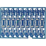
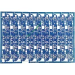
Panoramica del prodotto
UGPCB introduce il PCB di controllo del motore del robot, un bifacciale ad alta affidabilità circuito stampato progettato specificamente per i sistemi di controllo del movimento robotico. Questo prodotto utilizza il laminato in tessuto di vetro epossidico rivestito in rame Kingboard KB6160A e segue rigorosamente i requisiti delle specifiche IPC-4101E/21. Il materiale offre un'eccellente resistenza termica, resistenza meccanica, e prestazioni elettriche. Queste qualità forniscono una solida base hardware per applicazioni di controllo e azionamento di motori robotici.
Questocircuito di controllo del motore del robot misure 96.83 × 30.6 mm con a 1.6 spessore tavola mm. Presenta una struttura di cablaggio bifacciale (2 strati) che soddisfa i requisiti di spazio dei sistemi di controllo robotici compatti. Il prodotto offre un'apertura minima di 0.27 mm, larghezza/spaziatura della traccia di 0.32/0.382 mm, e spessore della lamina di rame di 35/35 μm (1 oz di rame su entrambi i lati). Il trattamento superficiale utilizza OSP (Conservanti di saldabilità organica) finitura antiossidante. La maschera di saldatura è disponibile in blu, e la legenda appare in bianco.
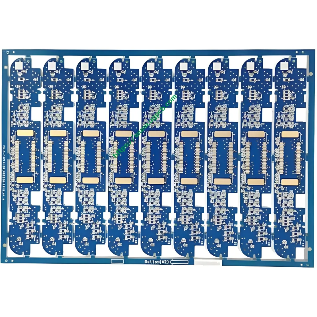
Definizione del prodotto e conformità agli standard
ILPCB di controllo del motore del robot è un circuito stampato specializzato per azionamenti di giunti robotici, controllo del servomotore, schede di controllo del movimento, e applicazioni simili. Questo PCB trasmette segnali di azionamento del motore, distribuisce il potere, ed esegue la logica di controllo. Funziona come un componente critico nel robot “sistema nervoso.”
Questo prodotto è sottoposto a produzione e progettazione in stretta conformità con i seguenti standard internazionali:
- IPC-4101E/21 (Specifiche dei materiali di base per pannelli stampati rigidi e multistrato): Il laminato KB6160A soddisfa queste specifiche.
- IPC-6012E (Specifiche di qualificazione e prestazione per circuiti stampati rigidi): Ciò copre i requisiti di qualificazione e prestazione per i pannelli a doppia faccia.
- IPC-A-600K (Accettabilità dei circuiti stampati): Questo serve come standard di accettazione illustrato.
- IPC-4555 (Specifiche prestazionali per preservanti organici di saldabilità ad alta temperatura per schede stampate): Questo governa il processo di finitura superficiale OSP.
- UL 94 V-0 (Norma sull'infiammabilità): Questo rappresenta il più alto grado di ritardanza di fiamma.
Origine dati: Le informazioni standard di cui sopra provengono da IPC (Associazione che collega le industrie elettroniche) documenti standard ufficiali e UL (Laboratori sottoscrittori) norme di sicurezza.
Punti salienti del design
Selezione dei materiali: i vantaggi principali del KB6160A
KB6160A è un laminato convenzionale rivestito in tessuto di vetro epossidico FR-4 rivestito in rame di Kingboard Laminates Holdings. I parametri chiave delle prestazioni vengono visualizzati di seguito:
| Proprietà | Metodo di prova (IPC-TM-650) | Specifica | Valore tipico |
|---|---|---|---|
| Temperatura di transizione vetrosa (Tg) | 2.4.25 (DSC) | ≥130℃ | 135℃ |
| Stress termico (288℃ Galleggiante per saldatura) | 2.4.13.1 | ≥10 secondi | ≥180 s |
| Cte (A1) Asse Z. | 2.4.24 (TMA) | - | 58 ppm/℃ |
| Cte (A2) Asse Z. | 2.4.24 (TMA) | - | 286 ppm/℃ |
| Temperatura di decomposizione termica (Td) | 2.4.24.6 (TGA) | - | 305℃ |
| Infiammabilità (Valutazione della fiamma) | UL 94 | V-0 | V-0 |
| Resistività superficiale | 2.5.17.1 | ≥1,0×10⁴ MΩ | 1.0×10⁶ MΩ |
| Resistività al volume | 2.5.17.1 | ≥1,0×10⁶ MΩ·cm | 1.0×10⁸ MΩ·cm |
| Costante dielettrica (@1 MHz) | 2.5.5.2 | ≤5,4 | 4.58 |
| Fattore di dissipazione (@1 MHz) | 2.5.5.2 | ≤0,035 | 0.022 |
| Resistenza alla sbucciatura del rame (125℃) | 2.4.8 | ≥0,70 N/mm | 1.70 N/mm |
| Forza di flessione (Ordito) | 2.4.4 | ≥415 N/mm² | 565 N/mm² |
Origine dati: I dati sopra riportati provengono dalla documentazione tecnica ufficiale del prodotto Kingboard Laminates Holdings e dagli standard del metodo di prova IPC-TM-650.
Il laminato KB6160A offre queste caratteristiche principali:
- Blocco UVB e compatibilità AOI: Il materiale supporta il blocco della luce UV e ispezione ottica automatica (AOI). Ciò migliora l'efficienza e la precisione della produzione di PCB.
- Eccellente stabilità dimensionale: I valori tipici di deformazione raggiungono solo 0.17%/0.35%, ben al di sotto del requisito standard IPC di ≤1,0%.
- Prestazioni termiche superiori: Tg≥130℃ (tipico 135 ℃) con resistenza allo stress termico di ≥180 secondi a 288℃ galleggiante di saldatura.
- Eccellenti proprietà meccaniche: La tipica resistenza alla flessione raggiunge 565 N/mm².
Traccia larghezza/spaziatura e design dell'apertura
Questo prodotto presenta un'apertura minima di0.27 mm e larghezza/spaziatura della traccia di0.32/0.382 mm. Secondo IPC-2221, lo standard di progettazione di base per tutti i documenti della serie IPC-2220, la capacità di trasporto di corrente del conduttore segue questa formula:
io = k × ΔT^0,44 × A^0,725
Dove I rappresenta la capacità di trasporto di corrente (UN), k è il fattore di correzione (0.024 per gli strati interni, 0.048 per gli strati esterni), ΔT è l'aumento della temperatura (℃), e A è l'area della sezione trasversale del conduttore (milioni²). Per conduttori dello strato esterno con aumento di temperatura di 10 ℃, UN 0.32 larghezza traccia mm (circa 12.6 mil) con 35 μm (1 oz) lo spessore del rame fornisce circa1.2 UN capacità attuale. Questo design supporta pienamente la trasmissione del segnale e requisiti di azionamento di corrente moderati per applicazioni di controllo di motori robotici.
Spessore del cartone e impilamento degli strati
IL 1.6 mm lo spessore del pannello rappresenta lo spessore standard per i pannelli rigidi PCB. Bilancia la resistenza meccanica con le prestazioni elettriche. IL a doppia faccia (2-strato) La struttura del cablaggio consente un'efficace partizione dei livelli di alimentazione e segnale in uno spazio limitato. Ciò soddisfa i principi di partizione funzionale dei circuiti di controllo dei motori robotici, separare chiaramente l'azionamento del motore, controllore principale, interfaccia del sensore, e moduli di gestione dell'energia.
Principio di funzionamento
ILPCB di controllo del motore del robot funziona come “centro neurale” all’interno dei sistemi robotici. Il suo principio di funzionamento può essere compreso attraverso diversi livelli:
Trasmissione del segnale: Tracce di rame sul PCB formano reti elettriche che trasmettono con precisione segnali di controllo dall'MCU principale (microcontrollore) ai chip dei driver dei motori come gate driver e pre-driver. IL 0.32 La larghezza della traccia di mm garantisce l'integrità del segnale. IL 0.27 L'apertura minima di mm supporta pacchetti di componenti ad alta densità tra cui QFN e BGA.
Azionamento di potenza: A doppia faccia 1 oz (35 μm) il rame fornisce un'ampia capacità di trasporto di corrente per le correnti elevate transitorie richieste dagli azionamenti dei motori. I componenti ad alta potenza sono posizionati vicino ai bordi della scheda per facilitare la dissipazione del calore.
Compatibilità elettromagnetica (EMC): Una corretta progettazione della messa a terra e strategie di instradamento sopprimono efficacemente le interferenze elettromagnetiche (EMI) generato durante la commutazione del motore. Ciò garantisce segnali di controllo puliti in tutto il sistema.
Applicazioni del prodotto
Questocircuito di controllo del motore del robot serve le seguenti applicazioni:
- Controllo della trasmissione congiunta di robot industriali: Controllo servomotore per bracci robotici multiasse
- Controllo del movimento del robot di servizio: Feedback sulla trasmissione del telaio e sulla velocità delle ruote per robot di consegna e robot di guida
- Piattaforme robotiche educative: Schede di controllo per robotica didattica e da laboratorio
- Sistemi di controllo del volo UAV: Regolazione e controllo della velocità del motore
- Domotica intelligente: Controllo dell'azionamento del motore per tende elettriche e serrature intelligenti
- Attrezzature per l'automazione dell'ufficio: Controllo motore per stampanti e fotocopiatrici
- Apparecchiature per le comunicazioni: Controllo del motore della ventola di raffreddamento per stazioni base e interruttori
Classificazione del prodotto
Questo prodotto può essere classificato scientificamente in più dimensioni secondo gli standard internazionali dei circuiti stampati:
| Dimensione Classificazione | Categoria | Norma governativa |
|---|---|---|
| Tipo di materiale di base | Scheda stampata rigida FR-4 | IPC-4101E/21 |
| Conteggio degli strati conduttivi | Tavola bifacciale (2-Strato) | IPC-6012E |
| Tramite tipo | Foro passante placcato (PTH) Tavola bifacciale | IPC-6012E |
| Ritardo di fiamma | UL 94 V-0 Valutato | UL 94 |
| Finitura superficiale | OSP (Conservanti di saldabilità organica) | IPC-4555 |
| Dominio dell'applicazione | PCB di controllo robotica/industriale | - |
Origine dati: Gli standard di classificazione si basano su IPC-4101E, IPC-6012E, IPC-4555, e UL 94 specifiche internazionali.
Materiali utilizzati
Materiale di base: laminato in tessuto di vetro epossidico rivestito in rame KB6160A
KB6160A appartiene allaLaminato rivestito in rame con tessuto di vetro epossidico FR-4 famiglia. La sua composizione materiale include:
- Rinforzo: Tessuto in vetro E di grado elettronico
- Legante: Resina epossidica ignifuga
- Lamina di rame: Elettrodepositato (Ed) rame, 35 μm (1 oz) spessore
- Sistema ritardante di fiamma: UL 94 V-0 additivi ritardanti di fiamma conformi
Finitura superficiale – OSP (Conservanti di saldabilità organica)
L'OSP è un rivestimento organico sottile applicato su superfici di rame nudo. Previene l'ossidazione del rame e preserva la saldabilità. Secondo IPC-4555, la durata di conservazione dei rivestimenti OSP èun minimo di sei mesi.
Vantaggi della finitura superficiale OSP:
- Conveniente: Più economico dell'ENIG (Oro per immersione in nichel chimico) o HASL (Livellamento della saldatura ad aria calda)
- Rispettoso dell'ambiente: Pienamente compatibile con i processi di saldatura senza piombo
- Buona saldabilità: Adatto per prodotti con cicli di vita da brevi a medi o ambienti benigni
Maschera di saldatura e leggenda
- Maschera di saldatura: Inchiostro blu che fornisce protezione isolante e previene i ponti di saldatura
- Leggenda: Inchiostro bianco per l'identificazione dei componenti e la guida all'assemblaggio
Riepilogo dei parametri di prestazione
| Parametro | Specifica |
|---|---|
| Tipo laminato | KB6160A (Kingboard FR-4) |
| Spessore della scheda | 1.6 mm |
| Conta dei strati | 2 Strati (Doppia faccia) |
| Dimensione del consiglio | 96.83 × 30.6 mm |
| Apertura minima | 0.27 mm |
| Larghezza minima di traccia | 0.32 mm |
| Spaziatura minima della traccia | 0.382 mm |
| Spessore di lamina di rame | 35/35 μm (1 oz entrambi i lati) |
| Finitura superficiale | OSP Antiossidante |
| Colore maschera di saldatura | Blu |
| Colore legenda | Bianco |
| Tg (Temperatura di transizione vetrosa) | ≥130℃ (Tipico 135 ℃) |
| Valutazione della fiamma | UL 94 V-0 |
| Stress termico (288℃) | ≥10 secondi (Tipico ≥180 s) |
Caratteristiche strutturali
- Instradamento su due lati: Sia lo strato superiore che quello inferiore contengono circuiti, aumentando efficacemente la densità di routing
- Foro passante placcato (PTH) progetto: Abilita l'interconnessione elettrica tra gli strati
- Protezione superficiale OSP: La protezione dall'ossidazione della superficie del rame garantisce l'affidabilità della saldatura
- Maschera per saldatura blu con legenda bianca: Il chiaro contrasto visivo facilita il montaggio e l'ispezione
- 1.6 spessore pannello standard mm: Bilancia la resistenza meccanica con la produzione standardizzata
Processo di produzione
UGPCB produce ilPCB di controllo del motore del robot attraverso questo flusso di processo standardizzato:
- Taglio del materiale: I grandi pannelli rivestiti in rame KB6160A vengono tagliati in base alle dimensioni dei pannelli di produzione
- Perforazione: CNC la perforazione a controllo numerico raggiunge il 0.27 apertura minima mm
- Rame chimico/placcatura a pannello: Deposizione chimica del rame seguita da galvanica del pannello per la metallizzazione dei fori
- Trasferimento del modello dello strato esterno: Laminazione → esposizione → sviluppo crea lo schema del circuito
- Placcatura con motivo: Il rame e il rame stagno-piombo sono placcati elettroliticamente sul modello del circuito
- Incisione: Il foglio di rame esposto viene rimosso per formare i circuiti finali
- Sverniciatura dello stagno: Il resist di stagno-piombo viene rimosso
- Trattamento superficiale OSP: Il conservante organico per la saldabilità OSP viene applicato secondo IPC-4555
- Stampa della maschera di saldatura: Viene applicato l'inchiostro blu della maschera di saldatura, esposto, e sviluppato
- Stampa della legenda: I caratteri identificativi bianchi sono serigrafati
- Instradamento del profilo: Il routing CNC costituisce la finale 96.83 × 30.6 dimensioni mm
- Test elettrici: La sonda mobile o il test universale verifica le condizioni di aperto/corto
- Ispezione finale: Ispezione visiva e dimensionale secondo IPC-A-600K
- Imballaggio e spedizione: Confezionamento sottovuoto con barriera antiumidità
Scenari di applicazione
Scenario 1: Controllo servoazionamento robot industriali
Nei robot industriali a sei assi, QuestoPCB funge da scheda di controllo del servoazionamento. Riceve comandi di movimento dal computer host. I segnali di controllo PWM viaggiano 0.32 mm tracce agli stadi driver IGBT o MOSFET, ottenere un controllo preciso della coppia e della velocità dei servomotori.
Scenario 2: Azionamento del telaio del robot di servizio
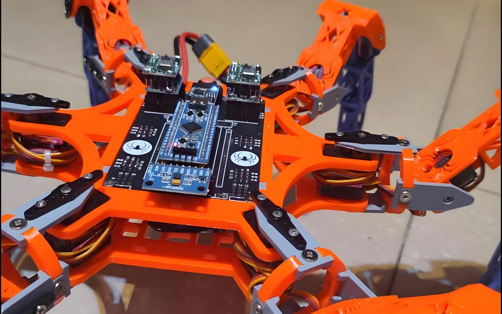
Nei robot di consegna e negli AGV (Veicoli a guida automatizzata), Questocircuito funziona come il nucleo per il controllo dell'azionamento indipendente a doppio motore. Controlla in modo indipendente la velocità e lo sterzo delle ruote motrici sinistra e destra, consentendo la corsa in linea retta e la rotazione sul posto.
Scenario 3: Piattaforme di sviluppo di robot educativi
Nei laboratori universitari di robotica e nei maker space, QuestoPCB di controllo del motore del robot funge da scheda madre per i sistemi di controllo robotici. Supporta lo sviluppo degli studenti e la verifica degli algoritmi di azionamento del motore, incluso il FOC (Controllo orientato al campo) e regolazione della velocità PID.
Scenario 4: Controllo della velocità del motore UAV
Nei quadricotteri, questo PCB può funzionare come ESC (Regolatore elettronico di velocità) scheda di controllo. Converte i comandi del controller di volo in segnali di azionamento del motore, ottenere il controllo della risposta ad alta velocità dei motori brushless.
Perché scegliere il PCB di controllo motore robot di UGPCB?
- Piena conformità agli standard internazionali: I prodotti sono progettati e realizzati secondo IPC-4101E/21, IPC-6012E, IPC-A-600K, IPC-4555, e UL 94 V-0
- Garanzia materiale premium: Kingboard KB6160A FR-4 laminato con Tg ≥130℃, UL 94 V-0 Valutazione della fiamma, e resistenza allo stress termico ≥180 secondi
- Produzione di alta precisione: 0.27 apertura minima mm e 0.32 La larghezza minima della traccia mm soddisfa i requisiti di instradamento ad alta densità
- Servizio unico: Supporto dell'intera catena, dall'ottimizzazione della progettazione PCB e dall'approvvigionamento dei componenti all'assemblaggio SMT/DIP e ai test funzionali
- 10+ anni di esperienza nel settore: Servire 3,000 clienti aziendali a livello globale
UGPCB è un fornitore leader a livello mondiale di progettazione PCB, produzione, e servizi di assemblaggio PCBA. Fondato in 2014, l'azienda è impegnata a fornire soluzioni PCB di alta precisione e altamente affidabili a clienti in tutto il mondo.
Richiedi un preventivo e dei campioni oggi stesso
UGPCB supporta il tuoPCB di controllo del motore del robot progetto con:
- ✅ DFM gratuito (Progettazione per la produzione) rapporti
- ✅ Prototipazione rapida con 24-ora consegna disponibile
- ✅ Produzione in volume con 20%+ tassi di rendimento superiori alla media del settore
- ✅ Team di ingegneri professionisti che fornisce supporto tecnico
📧Contattaci per un preventivo gratuito: Visita il sito Web UGPCB per inviare i file Gerber e la distinta base. Ricevi un preventivo automatizzato leader del settore.
📞Linea diretta: Raggiungici tramite la chat online o l'e-mail del nostro sito web.
Dichiarazione dell'origine dei dati
Tutti i dati tecnici e le informazioni standard citate in questo articolo provengono dalle seguenti fonti autorevoli:
- Kingboard Laminati Holdings Ltd. — Documentazione tecnica del prodotto KB-6160A (Informazioni tecniche KB)
- IPC (Associazione che collega le industrie elettroniche) — Specifiche IPC-4101E/21 per i materiali di base per schede stampate rigide e multistrato, IPC-6012E Qualificazione e specifiche prestazionali per schede stampate rigide, Accettabilità IPC-A-600K dei circuiti stampati, Specifiche prestazionali IPC-4555 per conservanti organici di saldabilità ad alta temperatura (OSP) per schede stampate, Manuale dei metodi di prova IPC-TM-650, Standard generico IPC-2221 sulla progettazione di schede stampate
- UL (Laboratori sottoscrittori) —UL 94 Norma per prove di infiammabilità di materie plastiche per parti di dispositivi ed apparecchi
- Database dei materiali PCBWay — Parametri tecnici KB-6160/6160A/6160C
- Documentazione tecnica OSHPpark — Scheda delle specifiche del substrato KB6160A
Disclaimer: I valori tipici sopra riportati sono dati di test di laboratorio forniti solo come riferimento. Le prestazioni effettive del prodotto possono variare a seconda dei processi di produzione e degli ambienti applicativi.













