


IO. Panoramica del prodotto
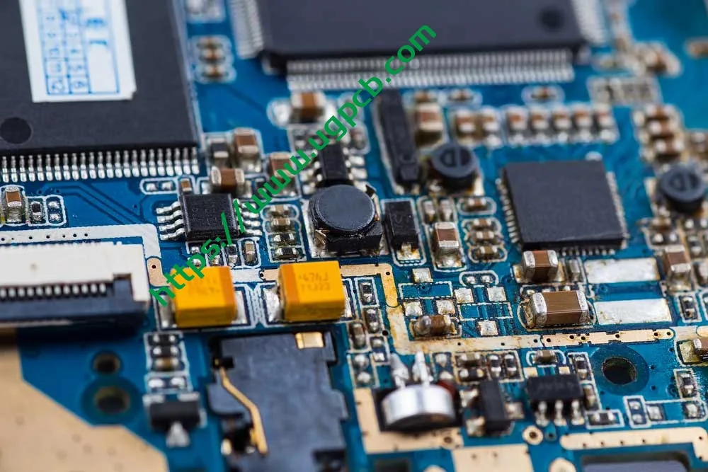
La scheda PCB a foro passante a doppia faccia UGPCB è una scheda rigida a 2 strati ad alte prestazioni circuito stampato costruito su un substrato vetro-epossidico FR-4 utilizzando un foro passante placcato (PTH) tecnologia. La tavola misura 86.9 × 73.58 mm con spessore di mm 1.0 mm, spessore della lamina di rame di 1/1 OZ (35 μm sia sugli strati esterni che su quelli interni), e un livellamento della saldatura ad aria calda senza piombo (Sanguinare) finitura superficiale. La maschera di saldatura è verde, e la legenda serigrafica è bianca.
Un PCB a foro passante a doppia faccia (circuito stampato a doppia faccia) presenta circuiti conduttivi su entrambi i lati del substrato isolante, con fori passanti placcati che consentono l'interconnessione elettrica tra i due strati. Rispetto ai PCB a lato singolo, I PCB a doppia faccia offrono una densità di routing superiore del 60%–80% e supportano progetti di circuiti più complessi. UGPCB, supportato da sistemi di qualità certificati ISO e processi di produzione conformi a IPC, fornisce PCB a foro passante a doppia faccia di alta qualità e chiavi in mano PCB servizi ai produttori di elettronica in tutto il mondo.
Ii. Definizione del prodotto e specifiche tecniche
Secondo IPC-6012F Specifiche di qualificazione e prestazione per circuiti stampati rigidi (pubblicato a settembre 2023), il PCB a foro passante a doppia faccia è classificato come un circuito stampato rigido con fori passanti placcati (Tipo 2). La sua caratteristica principale è il collegamento elettrico tra i conduttori su entrambi i lati attraverso pareti forate placcate in rame. UGPCB produce questo prodotto in piena conformità con IPC-6012F e soddisfa la classe 2 requisiti di prestazione (apparecchiature elettroniche di servizio dedicate).
Specifiche chiave:
| Parametro | Specifica |
|---|---|
| Materiale del substrato | FR-4 (Ignifugo UL 94 V-0) |
| Numero di strati | 2 strati (a doppia faccia) |
| Spessore della scheda | 1.0 mm |
| Dimensioni della scheda | 86.9 × 73.58 mm |
| Diametro minimo del foro | 0.236 mm |
| Larghezza minima della linea / Spaziatura | 0.32 × 0.37 mm |
| Spessore di lamina di rame | 1/1 OZ (ca. 35 μm su ciascun lato) |
| Finitura superficiale | HASL senza piombo (Livellamento della saldatura ad aria calda) |
| Maschera di saldatura / Leggenda | Maschera di saldatura verde / Serigrafia bianca |
Iii. Linee guida per la progettazione
3.1 Selezione del materiale del substrato: valore ingegneristico di FR-4
FR-4 è una designazione di grado ignifugo stabilita dalla National Electrical Manufacturers Association (NO). Le lettere “FR” sta per ritardante di fiamma, e il numero “4” denota un sistema di resina epossidica rinforzato con tessuto di vetro. Per IPC-4101 Specifiche dei materiali di base per pannelli stampati rigidi e multistrato, FR-4 Grado A1 rappresenta il livello prestazionale principale con resistenza meccanica ottimale, proprietà elettriche, e affidabilità a lungo termine.
Indicatori chiave di prestazione di FR-4 (Fonte: IPC-4101 e standard di settore):
-
Temperatura di transizione vetrosa (Tg): 130–140°C (norma FR-4)
-
Costante dielettrica (Non so) @ 1 GHz: 4.2–4.5
-
Fattore di dissipazione (Df) @ 1 GHz: ≤ 0.020
-
Punteggio di infiammabilità: UL 94 V-0
-
Assorbimento d'acqua (24 ore): ≤ 0.10%
L'FR-4 rimane il materiale di substrato predominante nell'industria dei PCB perché offre un eccezionale equilibrio di resistenza meccanica, isolamento elettrico, stabilità dimensionale, e lavorabilità.
3.2 Standard di progettazione dei circuiti secondo IPC-2221
Per IPC-2221 Standard generico sulla progettazione di schede stampate, la progettazione della larghezza del conduttore deve tenere conto della capacità di trasporto di corrente, aumento della temperatura, e spessore del rame. La formula della capacità di trasporto di corrente IPC-2221 è:
I = k · ΔT^0,44 · A^0,725
Dove:
-
I = Portata massima di corrente (UN)
-
k = Costante empirica (0.048 per gli strati esterni, 0.024 per gli strati interni)
-
ΔT = Aumento di temperatura consentito (° C.)
-
A = Area della sezione trasversale del conduttore (milioni²), dove A = L × T
Il prodotto UGPCB presenta una larghezza di linea di 0.32 mm (ca. 12.6 mil), interlinea di 0.37 mm (ca. 14.6 mil), e spessore del rame di 1 OZ (35 μm). Per una traccia dello strato esterno con un aumento di temperatura di 10°C:
A = 0.32 mm × 0.035 mm = 0.0112 mm² ≈ 17.36 milioni²
io = 0.048 × 10^0,44 × 17,36^0,725 ≈ 0.048 × 2.75 × 7.82 ≈ 1.03 UN
Questa larghezza del conduttore supporta circa 1 A di corrente, soddisfa le esigenze di potenza e trasmissione del segnale della maggior parte dei dispositivi elettronici di consumo e di controllo industriale. IPC-2221 consiglia di limitare l'aumento massimo della temperatura a 10°C o 20°C per preservare la durata di servizio del PCB.
3.3 Design del diametro del foro e delle proporzioni
Il rapporto d'aspetto di un foro passante è una metrica fondamentale per valutare la difficoltà di perforazione e metallizzazione del foro. La formula è:
Proporzioni = Spessore della scheda / Diametro del foro praticato
Per il prodotto UGPCB con 1.0 spessore del pannello mm e 0.236 diametro minimo del foro mm:
Proporzioni = 1.0 / 0.236 ≈ 4.24:1
Questo rapporto d'aspetto è ben al di sotto del limite superiore consigliato dal settore 10:1 e la soglia di progettazione conservativa di 8:1. Indica bassa difficoltà di foratura e metallizzazione, tassi di rendimento elevati, costi controllati, e affidabilità garantita attraverso il foro.
3.4 Riferimento per la progettazione del modello di terreno
Per IPC-7351 Requisiti generici per la progettazione del montaggio superficiale e lo standard del modello del terreno, la progettazione del modello del terreno deve garantire un'adeguata formazione del raccordo di saldatura e soddisfare la saldabilità, ispezionabilità, e requisiti di rilavorabilità. Per componenti a foro passante, il diametro del terreno è generalmente consigliato a 1,8–2,2 volte il diametro del foro per garantire una larghezza dell'anello anulare sufficiente.
IV. Principio di funzionamento
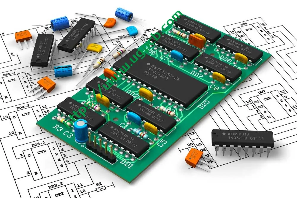
Il PCB a foro passante a doppia faccia funziona su tre tecnologie principali:
1. Instradamento fronte-retro — Gli schemi dei circuiti conduttivi sono incisi sia sulla superficie superiore che su quella inferiore del substrato isolante FR-4, consentendo il posizionamento dei componenti su entrambi i lati. Ciò aumenta significativamente la densità del circuito e la flessibilità di progettazione.
2. Foro passante placcato (PTH) Interconnessione — Dopo la perforazione, la deposizione chimica di rame e la placcatura di rame elettrolitico creano uno strato conduttivo sulle pareti del foro. Questo crea una bassa resistenza, collegamenti elettrici altamente affidabili tra gli strati superiore e inferiore. Secondo la classe IPC-6012F 2, lo spessore medio minimo del rame placcato sulle pareti dei fori deve essere ≥ 20 μm.
3. Assemblaggio e saldatura dei componenti — I componenti sono montati tramite foro passante (Tht) o montaggio superficiale (SMT) tecniche e collegati elettricamente tramite saldatura a rifusione o ad onda, producendo un PCBA completamente funzionale (Gruppo a circuito stampato) modulo.
V. Classificazione del prodotto
Secondo il sistema di classificazione IPC-6012F per i circuiti stampati rigidi, Il prodotto UGPCB è classificato come segue:
| Dimensione Classificazione | Categoria |
|---|---|
| Per costruzione | Scheda stampata rigida con fori passanti placcati, Doppia faccia (Tipo IPC-6012F 2) |
| Per classe di prestazione | Classe 2 (Assistenza dedicata per apparecchiature elettroniche) |
| Per materiale del substrato | FR-4 Laminato in tessuto di vetro epossidico (IPC-4101/21) |
| Per conteggio strati | 2-Scheda a strati |
| Per finitura superficiale | HASL senza piombo |
| Per grado di infiammabilità | UL 94 V-0 |
Per dominio dell'applicazione, questo prodotto rientra nella PCB bifacciale di grado industriale generale categoria, adatto per l'elettronica di consumo, controlli industriali, Attrezzatura di comunicazione, Adattatori di potenza, e altre applicazioni di media affidabilità.
VI. Composizione materiale
6.1 Substrato: laminato rivestito in rame FR-4
FR-4 è un laminato epossidico rinforzato con vetro composto da tessuto di vetro di grado elettronico come rinforzo e resina epossidica come legante, consolidato ad alta temperatura e pressione. È UL 94 V-0 il grado di infiammabilità significa quello nel test di combustione verticale, il materiale si autoestingue all'interno 10 secondi dopo ciascuna delle due applicazioni della fiamma da 10 secondi, senza gocce fiammeggianti che incendiano il cotone.
6.2 Lamina di rame — 1/1 OZ
Un'oncia (1 OZ) di lamina di rame ha uno spessore di 35 μm (1.37 mil). Utilizza UGPCB 1 Rame OZ su entrambi gli strati esterni (designato 1/1 OZ), garantendo la stessa capacità di trasporto di corrente e conduttività su entrambi i lati.
6.3 Finitura superficiale: HASL senza piombo
L'HASL senza piombo prevede l'immersione del PCB in una lega di saldatura fusa senza piombo (tipicamente Sn-Cu, Sn-Cu-Ni, o leghe Sn-Ag-Cu), quindi utilizzare lame ad aria calda ad alta pressione per livellare e rimuovere la saldatura in eccesso. Questo produce un'uniforme, rivestimento protettivo saldabile sulle superfici in rame. Il processo è conforme ai requisiti IPC-6012F e alle direttive ambientali RoHS.
6.4 Maschera di saldatura e leggenda
-
Maschera per saldatura verde — Copre tutte le aree del circuito tranne i pad, fornendo isolamento, protezione dall'ossidazione, e prevenzione dei cortocircuiti.
-
Legenda serigrafia bianca — Identifica i designatori di riferimento del componente, marcatori di polarità, numeri di parte della scheda, e livelli di revisione per facilitare l'assemblaggio e il debug.
VII. Prestazioni del prodotto
7.1 Prestazioni elettriche
| Parametro di prestazione | Valore | Norma di riferimento |
|---|---|---|
| Costante dielettrica (Non so) @ 1 GHz | 4.2–4.5 | IPC-4101 |
| Fattore di dissipazione (Df) @ 1 GHz | ≤ 0.020 | IPC-4101 |
| Resistenza di isolamento | ≥ 10^12Ω | IPC-6012F |
| Tensione di tenuta dielettrica | Per rigidità dielettrica | IPC-6012F |
7.2 Prestazioni meccaniche
| Parametro di prestazione | Valore | Norma di riferimento |
|---|---|---|
| Spessore della scheda | 1.0 mm± 10% | IPC-6012F |
| Resistenza alla sbucciatura del rame | ≥ 1.1 N/mm | IPC-6012F |
| Punteggio di infiammabilità | UL 94 V-0 | Norma UL |
| Tg (Temperatura di transizione vetrosa) | 130–140°C | IPC-4101 |
7.3 Affidabilità
Secondo la classe IPC-6012F 2 Requisiti, il prodotto deve superare le seguenti verifiche di affidabilità:
-
Prova di stress termico (288° C., 10 secondi, nessuna delaminazione o formazione di vesciche)
-
Test di adesione del rame placcato a foro passante (spessore medio minimo del rame nella parete del foro ≥ 20 μm)
-
Prova di saldabilità
-
Test di continuità elettrica e resistenza di isolamento
VIII. Struttura del prodotto
Il PCB a foro passante a doppia faccia di UGPCB presenta una struttura simmetrica a 2 strati. Dall'alto al basso:
-
Livello legenda superiore (Serigrafia bianca)
-
Strato superiore della maschera di saldatura (Inchiostro verde)
-
Strato superiore di lamina di rame (1 OZ, 35 μm)
-
FR-4 Substrato isolante (1.0 spessore mm)
-
Strato inferiore di lamina di rame (1 OZ, 35 μm)
-
Strato inferiore della maschera di saldatura (Inchiostro verde)
-
Livello legenda inferiore (Serigrafia bianca)
-
Fori passanti placcati (PTH) — Copre l'intero spessore della scheda con pareti dei fori placcate in rame che consentono l'interconnessione tra gli strati
IX. Caratteristiche del prodotto
-
Elevata densità di routing — Il routing su due lati offre una densità maggiore del 60%–80% rispetto alle schede su un solo lato, supportare progetti di circuiti più complessi.
-
Interconnessione through-hole altamente affidabile — Foro passante placcato (PTH) la tecnologia garantisce l'affidabilità elettrica a lungo termine tra gli strati, con spessore del rame nella parete del foro conforme alla classe IPC-6012F 2 Requisiti (≥ 20 media μm).
-
Eccellente ritardo di fiamma — Il substrato FR-4 è conforme a UL 94 V-0 grado di infiammabilità, garantire la sicurezza in condizioni operative anomale.
-
Senza piombo e rispettoso dell'ambiente — La finitura superficiale HASL senza piombo è conforme alle direttive ambientali RoHS.
-
Funzionalità del circuito a passo fine — Larghezza minima della linea di 0.32 mm e spaziatura minima di 0.37 mm ospitare il mezzo- ai progetti di circuiti ad alta densità.
-
Stabilità dimensionale superiore — Basso assorbimento d’acqua dell’FR-4 (≤ 0.10%) garantisce un cambiamento dimensionale minimo in ambienti umidi, preservando la precisione dell'assemblaggio.
-
Processo di produzione maturo - Con 1.0 spessore del pannello mm e 0.236 diametro minimo del foro mm, le proporzioni di solo 4.24:1 consente processi maturi, rendimenti elevati, e tempi di consegna brevi.
X. Flusso del processo di produzione
Il processo di produzione PCB standard a doppia faccia con foro passante di UGPCB:
1. Ispezione del materiale in entrata → Verificare lo spessore del laminato rivestito in rame FR-4, qualità della lamina di rame, e difetti visivi.
2. Taglio → Tagliare il laminato rivestito in rame di grande formato alla dimensione del pannello di lavoro (86.9 × 73.58 mm).
3. Perforazione → Utilizzare trapani CNC ad alta precisione per praticare tutti i fori passanti secondo la lima da trapano Gerber (diametro minimo 0.236 mm).
4. Foro passante placcato (PTH) → Depositare un sottile strato di semi di rame sulle pareti dei fori tramite deposizione chimica di rame.
5. Placcatura del pannello → Placcare elettroliticamente il rame per creare rame sulle pareti dei fori e sulla superficie fino allo spessore desiderato (1 OZ).
6. Trasferimento del modello → Film secco laminato, esporre, e svilupparsi per formare il modello di circuito resistente.
7. Incisione → Incidere via il rame non protetto per formare lo schema circuitale finale.
8. Spogliarello → Rimuovere la pellicola secca di resist dalle tracce del circuito.
9. Applicazione della maschera di saldatura → Applicare l'inchiostro verde per maschera di saldatura, esporre, e svilupparsi per esporre i cuscinetti.
10. Finitura superficiale → HASL senza piombo.
11. Stampa della legenda → Legenda serigrafica bianca serigrafata.
12. Instradamento / Taglio a V → Instradamento CNC al contorno della scheda finale.
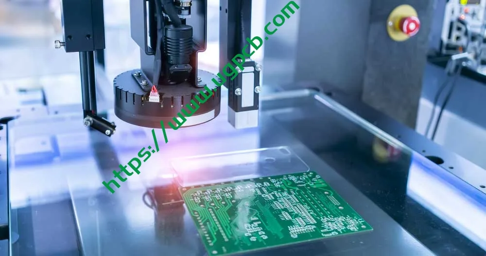
13. Test elettrici → Test della sonda mobile o del dispositivo per verificare l'integrità di apertura/cortocircuito.
14. Controllo qualità finale (FQC) → Ispezione visiva, campionamento dimensionale, e imballo per la spedizione.
XI. Scenari di applicazione
Schede PCB FR-4 a foro passante a doppia faccia UGPCB, con le loro prestazioni equilibrate e processi maturi, sono ampiamente utilizzati in:
11.1 Elettronica di consumo
-
Adattatori e caricabatterie di alimentazione
-
Schede di controllo degli elettrodomestici
-
Dispositivi domestici intelligenti
11.2 Controlli industriali
-
Controllori logici programmabili PLC
-
Moduli di potenza industriali
-
Strumentazione e contatori
11.3 Attrezzatura di comunicazione
-
Router e switch
-
Moduli di comunicazione
-
Dispositivi di conversione del segnale
11.4 Elettronica automobilistica
-
Caricabatterie di bordo
-
Moduli di controllo del corpo (non critici per la sicurezza)
-
Sistemi di infotainment
11.5 Dispositivi medici
-
Schede ausiliarie del monitor paziente
-
Attrezzature mediche portatili (Classe 2 applicabile)
XII. Vantaggi del prodotto e guida alla selezione
12.1 Perché scegliere i PCB a foro passante a doppia faccia UGPCB?
-
Controllo di processo conforme a IPC — Dalla scelta dei materiali al prodotto finito, piena conformità con IPC-6012F, IPC-4101, e altri standard internazionali.
-
Produzione ad alta precisione — Diametro minimo del foro di 0.236 mm e larghezza minima della linea di 0.32 mm incontra il medio- ai requisiti di progettazione ad alta densità.
-
Conformità ambientale — La finitura superficiale HASL senza piombo è conforme alla direttiva RoHS 2.0 direttive.
-
Affidabilità comprovata — Il substrato FR-4 è stato validato sul mercato per decenni con prestazioni costanti.
-
Consegna veloce — Le specifiche standard sono fornite di ampie materie prime, garantendo tempi di consegna affidabili.
12.2 Riferimento alla selezione
I PCB a foro passante a doppia faccia UGPCB sono la scelta ideale quando il tuo progetto soddisfa questi criteri:
-
Complessità del circuito moderata quella 2 gli strati possono ospitare
-
Frequenza operativa di seguito 1 GHz (FR-4 si comporta in modo eccellente in questa gamma)
-
Ambiente operativo a lungo termine non superiore a 120°C
-
Applicazioni sensibili ai costi che richiedono un valore elevato
XIII. Richiedi un preventivo
UGPCB si impegna a fornire produzione PCB di alta qualità e servizi PCBA chiavi in mano a clienti in tutto il mondo. Che tu abbia bisogno di PCB a doppia faccia con foro passante con specifiche standard o requisiti personalizzati (spessore speciale del pannello, peso del rame, finitura superficiale, Controllo dell'impedenza, ecc.), Il team di esperti di UGPCB fornisce pieno supporto dalla progettazione ingegneristica alla produzione in serie.
Ottieni un preventivo oggi stesso:
-
Invia file Gerber + specifiche: ricevi un preventivo entro 24 ore
-
Supporto dal prototipo alla produzione in grandi volumi
-
Progettazione gratuita per la produzione (DFM) revisione
Contatta UGPCB:
📧 Richieste di vendita: [sales@ugpcb.com]
🌐 Sito web: [www.ugpcb.com]
XIV. Dichiarazione dell'origine dei dati
Gli standard e i dati citati in questo documento provengono dalle seguenti organizzazioni autorevoli:
-
IPC (Associazione che collega le industrie elettroniche): IPC-6012F Specifiche di qualificazione e prestazione per circuiti stampati rigidi (settembre 2023); IPC-4101 Specifiche dei materiali di base per pannelli stampati rigidi e multistrato; IPC-2221 Standard generico sulla progettazione di schede stampate; IPC-7351 Requisiti generici per la progettazione del montaggio superficiale e lo standard del modello del terreno
-
UL (Laboratori sottoscrittori): UL 94 Norma per prove di infiammabilità di materie plastiche per parti di dispositivi ed apparecchi
-
NO (Associazione Nazionale Produttori Elettrici): Definizione della qualità del materiale FR-4
-
Dati tecnici standard del settore: Costante dielettrica FR-4, fattore di dissipazione, e altri parametri di proprietà del materiale













