
Quick Specifications
| Parameter | Detail |
|---|---|
| Base Material | Rogers RT/duroid 5870 (random micro‑glass fiber reinforced PTFE composite) |
| Layer Count | 2 layers |
| Total Board Thickness | 0.9 mm |
| Dielectric Thickness | 0.762 mm |
| Dielectric Constant (Dk) @ 10 GHz | 2.33 ± 0.02 (typical) |
| Dissipation Factor (Df) @ 10 GHz | 0.0012 (typical) |
| Flammability Rating | UL 94 V‑0 |
| Copper Weight | Base 0.5 oz (≈18 µm), finished 1 oz (≈35 µm) |
| Surface Finish | ENIG (Electroless Nickel Immersion Gold) |
| Key Applications | Commercial aerospace broadband antennas, microstrip and stripline circuits, millimeter‑wave equipment, military radar systems, missile guidance systems, point‑to‑point digital RF antennas |
What Is a Rogers RT5870 High‑Frequency PCB? Definition and Classification
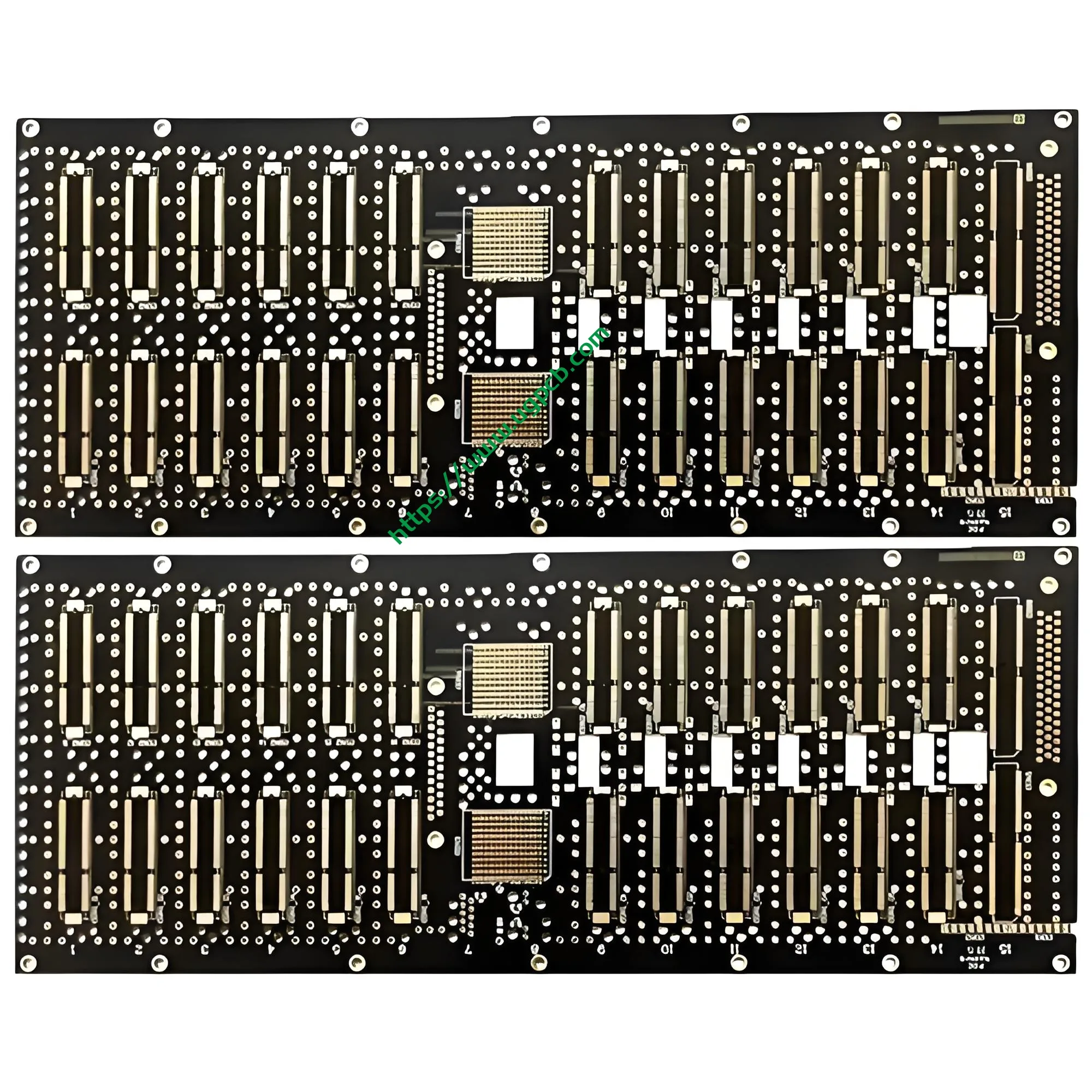
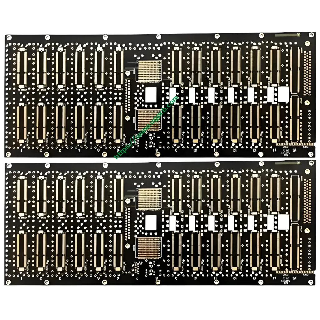
A Rogers RT5870 high‑frequency PCB uses Rogers RT/duroid 5870 laminate as its core dielectric. This laminate is a PTFE composite. Randomly oriented micro‑glass fibers reinforce the composite. Engineers designed it for demanding stripline and microstrip circuits.
From a PCB classification standpoint, the RT5870 board falls into these categories:
- By frequency – High‑frequency PCB (RF/microwave PCB) covering Ku‑band and above.
- By material system – PTFE‑based high‑frequency PCB. This differs from hydrocarbon ceramic‑filled or modified‑epoxy systems.
- By application – RF and microwave PCB with military/aerospace‑grade reliability.
- By layer count – Double‑sided PCB (standard). Multilayer configurations are also supported.
- By IPC specification – High‑speed/high‑frequency base material compliant with IPC‑4103.
Rogers RT/duroid 5870 first appeared in the 1960s. It has more than 60 years of field‑proven performance. It remains one of the industry’s most mature high‑frequency PCB material solutions.
Material Composition and PCB Stackup of UGPCB’s RT5870 Board
Core Substrate: Random Micro‑Glass Fiber Reinforced PTFE Composite
The heart of RT/duroid 5870 is a PTFE matrix. It contains uniformly distributed, randomly oriented micro‑glass fibers. This unique microstructure delivers two important properties. First, it provides isotropic electrical behavior. The dielectric constant stays consistent in X, Y, and Z directions. Second, it guarantees excellent Dk uniformity from panel to panel.
PCB Stackup
This product is a 2‑layer double‑sided high‑frequency PCB. Total board thickness measures 0.9 mm. The dielectric layer thickness is 0.762 mm. Copper conductors sit on both sides. The base copper weight is 0.5 oz (about 18 µm). After plating, the finished copper reaches 1 oz (about 35 µm). This design balances high‑frequency signal transmission with current‑carrying capacity.
Surface Finish: ENIG
UGPCB applies an ENIG (Electroless Nickel Immersion Gold) surface finish. We deposit a nickel‑phosphorus alloy layer (3–6 μm) first. Then we add a pure gold layer (0.05–0.1 μm). The nickel layer acts as a diffusion barrier. It prevents brittle intermetallic compounds during soldering. The gold layer delivers superior conductivity, corrosion resistance, and solderability. This finish perfectly matches the needs of high‑frequency signal transmission. It offers outstanding surface flatness and oxidation protection.
How It Works: Why Low Dk and Low Df Transform High‑Frequency PCB Performance
High‑frequency PCBs typically operate above 100 MHz. Microwave bands start at 2 GHz. At these frequencies, the dielectric material directly controls signal quality. Two parameters matter most.
Dielectric Constant (Dk) and Signal Propagation Speed
The signal propagation velocity v_p in a PCB transmission line follows this formula:
v_p = c / √(Dk)
Here, c is the speed of light in a vacuum (≈ 3 × 10⁸ m/s). With Dk = 2.33, the signal travels at about 65.5% of the speed of light (≈ 1.96 × 10⁸ m/s). This is significantly faster than on standard FR‑4 boards. FR‑4 has a Dk around 4.2–4.8. Its signals travel at only 46%–49% of light speed. Faster propagation means lower transmission delay. This advantage proves critical for phase‑sensitive radar and antenna systems.
Dissipation Factor (Df) and Signal Attenuation
The dissipation factor (Df, also called tan δ) measures how much electromagnetic energy a material turns into heat. A lower Df means less signal loss. RT/duroid 5870 achieves a Df of only 0.0012 at 10 GHz. That is 0.12%. Typical FR‑4 materials show Df values between 0.018 and 0.025. As a result, the RT5870 PCB reduces high‑frequency transmission loss by more than an order of magnitude.
Dispersion Control
Different frequencies can travel at different speeds in a dielectric. This effect is called dispersion. It distorts wideband signals. RT/duroid 5870 maintains a nearly constant Dk across a broad frequency range. This behavior minimizes dispersion. It makes the material a strong fit for wideband high‑frequency PCBs.
Design Essentials for RT5870 High‑Frequency Circuits
Controlled Impedance – Standard 50 Ω Design
Microstrip and stripline serve as the main transmission‑line structures in high‑frequency PCBs. Impedance depends on Dk, dielectric thickness, line width, and copper thickness. Using Dk = 2.33, dielectric thickness 0.762 mm, and 1 oz copper, a 50 Ω microstrip needs a line width of about 0.762 mm (30 mil). UGPCB tightly controls trace width and spacing during PCB fabrication. This keeps the characteristic impedance on target.
Low Moisture Absorption Design
RT/duroid 5870 absorbs only 0.02% water (D48/50% test condition). This ultra‑low moisture uptake prevents Dk drift and signal degradation in humid environments. It suits airborne avionics equipment extremely well.
Thermal Stability Design
The coefficient of thermal expansion (CTE) for RT/duroid 5870 is 22 ppm/°C (X), 28 ppm/°C (Y), and 173 ppm/°C (Z) across -55°C to 288°C. The dielectric constant thermal coefficient is -115 ppm/°C (-50°C to 150°C). The relatively high Z‑axis CTE demands careful attention to plated through‑hole (PTH) reliability. UGPCB meets this challenge with optimized plasma activation and electroless copper processes for PTFE. Our approach secures robust via connections.
Chemical Resistance and Machinability
PTFE materials are highly inert. RT/duroid 5870 resists all solvents and reagents used in etching and plating. At the same time, the laminate is easy to cut, shear, and machine. This supports precision fabrication of complex PCB outlines.
Performance Data Deep Dive (per IPC‑TM‑650 and Related Standards)
The following table lists the complete performance data for RT/duroid 5870 laminate. All values come from the official Rogers datasheet. Test methods align with the IPC‑TM‑650 series.
| Parameter | RT/duroid 5870 Typical Value | Test Method |
|---|---|---|
| Dielectric Constant (process) @ 10 GHz | 2.33 ± 0.02 | IPC‑TM‑650 2.5.5.5 |
| Dielectric Constant (design) @ 8–40 GHz | 2.33 | Differential Phase Length Method |
| Dissipation Factor @ 1 MHz | 0.0005 | IPC‑TM‑650 2.5.5.3 |
| Dissipation Factor @ 10 GHz | 0.0012 | IPC‑TM‑650 2.5.5.5 |
| Dk Temperature Coefficient (-50°C to 150°C) | -115 ppm/°C | IPC‑TM‑650 2.5.5.5 |
| Volume Resistivity | 2 × 10⁷ Mohm·cm | ASTM D257 |
| Surface Resistivity | 2 × 10⁷ Mohm | ASTM D257 |
| Thermal Conductivity @ 50°C | 0.22 W/m·K | ASTM D5470 |
| CTE X / Y / Z | 22 / 28 / 173 ppm/°C | IPC‑TM‑650 |
| Peel Strength (1 oz ED copper) | 27.2 lbs/in (4.8 N/mm) | IPC‑TM‑650 |
| Density | 2.2 gm/cm³ | — |
| Water Absorption | 0.02% | D48/50% |
| Flammability Rating | UL 94 V‑0 | UL 94 |
| Lead‑Free Process Compatible | Yes | — |
This data demonstrates why the RT5870 high‑frequency PCB excels in dielectric uniformity, low loss, humidity resistance, and fire safety.
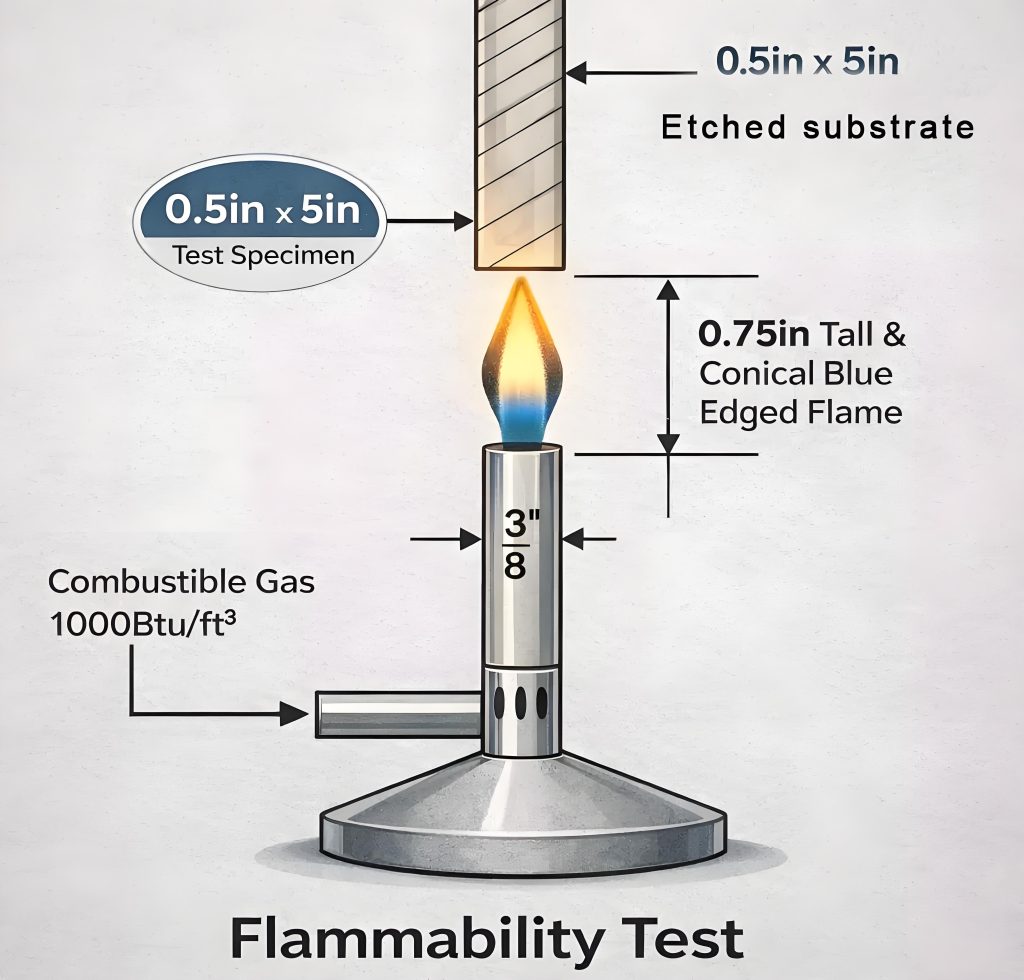
Why Does UL 94 V‑0 Matter?
UL 94 V‑0 is the highest flammability rating for plastic materials in devices. A V‑0 rating means the material self‑extinguishes within 10 seconds during a vertical burn test. Any burning drips will not ignite the cotton indicator. For avionics and military equipment, UL 94 V‑0 is a mandatory safety requirement. RT/duroid 5870 achieves this strict rating and supports lead‑free soldering. It fully meets the safety and environmental rules for aerospace and defense applications.
Key Features and Competitive Advantages
Five Core Technical Features
- Lowest electrical loss among reinforced PTFE high‑frequency materials.
- Ultra‑low moisture absorption – ideal for high‑humidity environments.
- Isotropic electrical properties – uniform Dk in all three directions.
- Wideband consistency – stable electrical performance from 1 MHz to Ku‑band and beyond.
- Excellent chemical resistance – withstands all standard PCB processing chemicals.
RT5870 vs. RT5880: How to Choose?
RT/duroid 5870 and RT/duroid 5880 both belong to the Rogers micro‑glass fiber reinforced PTFE family. Each product excels in different areas.
| Comparison | RT/duroid 5870 | RT/duroid 5880 |
|---|---|---|
| Dk @ 10 GHz | 2.33 ± 0.02 | 2.20 ± 0.02 |
| Df @ 10 GHz | 0.0012 | 0.0009 |
| CTE‑X (ppm/°C) | 22 | 31 |
| CTE‑Y (ppm/°C) | 28 | 48 |
| Peel Strength | 27.2 lbs/in | 31.2 lbs/in |
| Best For | High‑power radar, thermally stable systems | Ultra‑low‑loss communication, satellite |
The RT5870 board offers stronger thermomechanical stability and higher toughness. These qualities serve high‑power radar and avionics that endure intense thermal cycling. In comparison, RT5880 delivers a slightly lower Dk (2.20) and Df (0.0009). It wins on signal delay and insertion loss.
UGPCB’s RT5870 High‑Frequency PCB Manufacturing Process and Quality Control
Material Preparation and Cutting
We start with genuine Rogers RT/duroid 5870 laminates. We micro‑etch and acid‑clean the copper surface. This step removes oxides and organic contaminants.
Imaging and Etching
We use dry‑film photolithography to transfer the circuit pattern. We optimize etching parameters and apply compensation (etch factor) to tightly hold the 0.762 mm trace width and spacing. This discipline ensures impedance consistency across the high‑frequency PCB.
Drilling and Plating
After drilling, the PTFE hole walls receive plasma activation. Next, we apply electroless copper deposition. This step metallizes the holes and creates reliable through‑hole connections. UGPCB has established mature process parameters specifically for this PTFE PCB step.
Surface Finish – ENIG
We apply a chemical nickel‑gold process. We deposit a nickel layer of 3–6 μm first. Then we add a gold layer of 0.05–0.1 μm. Gold provides low contact resistance and excellent solderability. Nickel forms a diffusion barrier. This ensures long‑term reliability of solder joints on your RT5870 PCBA.
Electrical Test and Inspection
We perform 100% electrical continuity and isolation testing. We also conduct visual inspection according to IPC‑A‑600. Every high‑frequency PCB meets our shipment standard.
UGPCB Quality Assurance
UGPCB operates under ISO 9001 quality management and IPC‑A‑600 workmanship standards. Our high‑frequency PCB manufacturing is fully traceable. We inspect incoming Rogers base materials and perform final checks on every outgoing board.
Typical Application Scenarios for RT5870 PCBs and PCBA Assemblies
Commercial Aerospace Broadband Antennas
RT5870’s Dk uniformity and low loss make it a go‑to PCB material for airborne broadband antenna feed networks. In Ku‑band antennas, signals run through power‑divider circuits. These networks demand strict dielectric loss and phase consistency. RT5870 high‑frequency PCBs meet those demands.
Microstrip and Stripline Circuits
Rogers originally designed RT/duroid 5870 for precision microstrip and stripline circuits. Whether you design filters, couplers, power dividers, or impedance‑transformation networks, this laminate provides a predictable dielectric environment. Your circuit performance stays repeatable.
Millimeter‑Wave Equipment
The low dissipation factor pushes RT5870 usage into Ku‑band and beyond. It supports 24 GHz, 60 GHz, and even 77 GHz millimeter‑wave applications. These include 5G mmWave small cells, automotive radar, and point‑to‑point microwave backhaul.
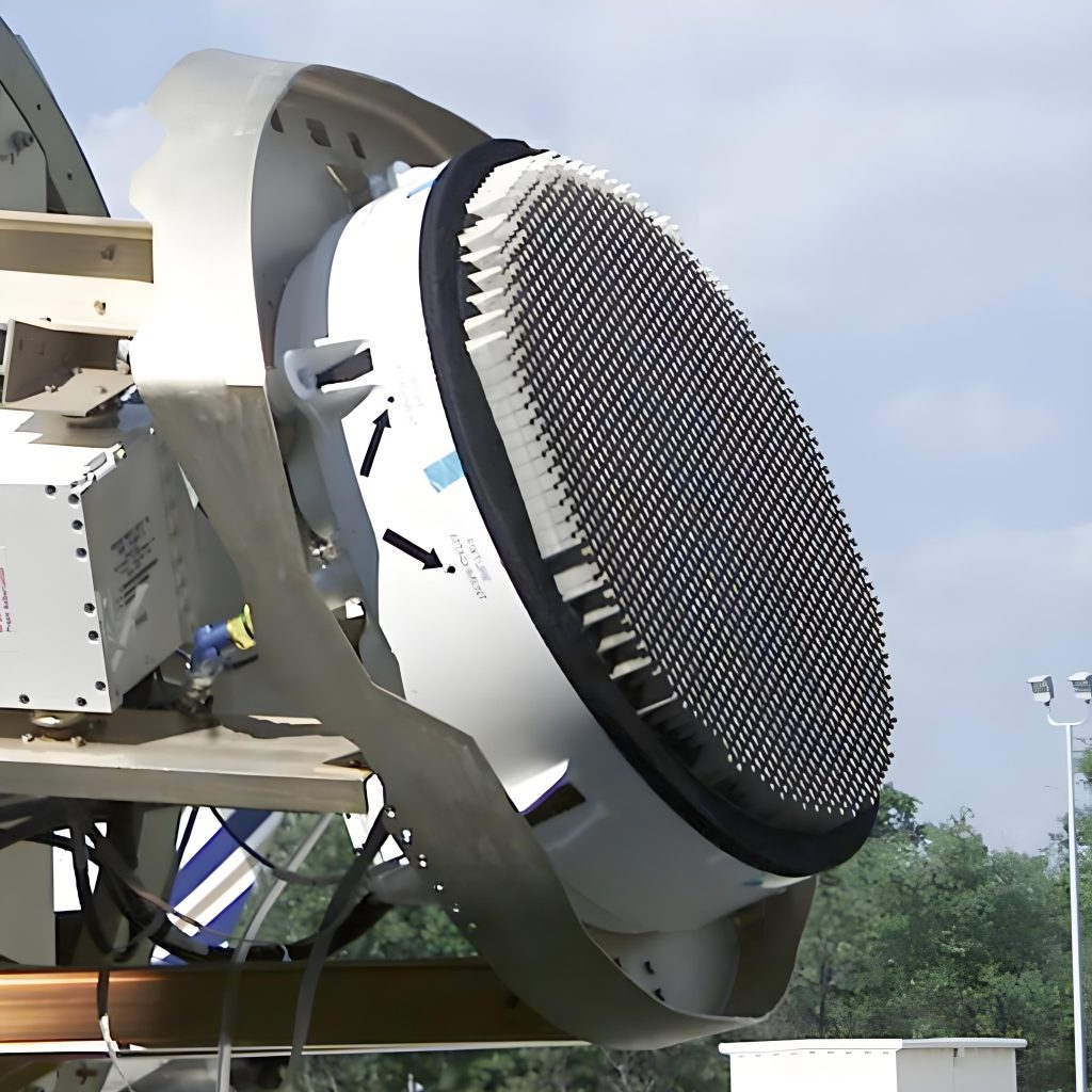
Military Radar Systems
Low loss and strong thermal stability satisfy the rigorous needs of military radar. RT5870 high‑frequency PCBs handle long‑pulse, high‑power signals reliably. You find them in airborne fire‑control radar and ground‑based early‑warning systems.
Missile Guidance Systems
Missile seeker transceiver modules face extreme temperature, vibration, and humidity. RT5870 absorbs almost no moisture (0.02%) and maintains stable electrical properties across a wide temperature range. This ensures signal integrity from launch to target.
Point‑to‑Point Digital RF Antennas
Point‑to‑point microwave links rely on precise antenna gain and beamwidth. RT5870’s superior Dk uniformity guarantees accurate phase alignment across large antenna arrays. Your PCB performance stays predictable element to element.
Delivery Parameters for the RT5870 High‑Frequency PCB
| Parameter | Specification |
|---|---|
| Base Material | Rogers RT/duroid 5870 |
| Layer Count | 2 layers |
| Total Board Thickness | 0.9 mm |
| Dielectric Thickness | 0.762 mm |
| Dk @ 10 GHz | 2.33 ± 0.02 |
| Df @ 10 GHz | 0.0012 |
| Copper (Base/Finished) | 0.5 oz / 1 oz |
| Trace Width / Spacing | 0.762 mm / 0.762 mm |
| Surface Finish | ENIG |
| Flammability Rating | UL 94 V‑0 |
| Dimensions | Custom |
| Hybrid Multilayer Support | Yes (RT5870 + FR‑4 or other Rogers materials) |
UGPCB PCBA Services for High‑Frequency Boards
Beyond bare high‑frequency PCBs, UGPCB provides one‑stop PCBA (Printed Circuit Board Assembly) services. For Rogers RT5870 board assembly, we offer:
- High‑frequency SMT assembly using low‑loss pad designs and precise stencil apertures.
- Fine‑pitch component soldering (BGA, QFN, and more).
- Tightly controlled reflow soldering profiles.
- AOI (Automated Optical Inspection) and X‑ray inspection.
- Functional testing at the system level.
When your project needs high‑frequency PCB plus PCBA turnkey delivery, please specify your PCBA requirements at the ordering stage.
Why Choose UGPCB? – Request Your Quote Today
- ✅ Rogers Authorized Channel Sourcing – Every RT5870 high‑frequency PCB starts with genuine original laminates.
- ✅ 20+ Years of High‑Frequency PCB Manufacturing – Deep expertise in RF and microwave circuit board fabrication.
- ✅ ISO 9001 Certified Manufacturing – Strict quality control from incoming materials to final shipment.
- ✅ Fast Prototyping and Volume Production – Competitive lead times for prototypes and flexible batch scheduling.
- ✅ Global Logistics – Serving North America, Europe, Asia‑Pacific, and other major markets.
- ✅ Expert Technical Support – Engineering assistance from design consultation through PCB production and PCBA.
Contact UGPCB for your Rogers RT5870 high‑frequency PCB or PCBA project.
- 📧 Email: sales@ugpcb.com
- 🌐 Website: www.ugpcb.com
- 📞 Live Chat: Available on our website
- 📋 Quick RFQ Form: Submit your Gerber files and requirements. We respond with a quotation within 24 hours.
Glossary
| Term | Definition |
|---|---|
| Dk (Dielectric Constant) | A measure of a material’s ability to store electric field energy. |
| Df (Dissipation Factor) | A measure of how much electromagnetic energy a material converts to heat; also called loss tangent. |
| PTFE | Polytetrafluoroethylene, a high‑performance fluoropolymer. |
| ENIG | Electroless Nickel Immersion Gold, a surface finish for high‑frequency PCBs. |
| CTE | Coefficient of Thermal Expansion. |
| PTH | Plated Through Hole, a via with conductive copper plating. |
| PIM | Passive Intermodulation. |
| RF | Radio Frequency, typically 100 MHz and above. |
| IPC | Association Connecting Electronics Industries, publisher of PCB standards. |
FAQ – Rogers RT5870 High‑Frequency PCBs
Q1: How do I choose between RT5870 and RT5880?
A1: RT5870 (Dk=2.33) provides better thermomechanical stability. It suits high‑power radar and avionics. RT5880 (Dk=2.20) offers even lower loss. It is ideal for ultra‑high‑frequency communication and satellite systems. See the comparison table in Section 6.2.
Q2: What is the minimum trace width and spacing?
A2: The minimum trace/space depends on copper thickness and your design. Our standard RT5870 product features 0.762 mm lines and spaces. For finer geometries, please contact UGPCB technical support.
Q3: Do you support multilayer and hybrid high‑frequency PCBs?
A3: Yes. We build multilayer RT5870 boards and hybrid stackups. We combine RT5870 with other Rogers materials (such as RO4350B, RT5880) or FR‑4.
Q4: What is the typical lead time?
A4: Prototype lead times vary by layer count and complexity. Our sales team can provide the fastest available schedule. Volume lead times appear in the official quotation.
Q5: How do high‑frequency PCBs differ from standard PCBs?
A5: High‑frequency PCBs use low‑Dk, low‑Df specialty substrates such as PTFE for RF/microwave signals. Standard FR‑4 boards have higher Dk (4.2–4.8) and higher loss. They suit only low‑frequency digital or analog circuits.
Legal and Compliance Notice
All technical parameters come from the official Rogers Corporation RT/duroid 5870/5880 datasheets. Values are typical. Normal process variations may occur between production batches. IPC‑4103 references serve to indicate the classification system and test methods for high‑frequency substrates. The UL 94 V‑0 flammability rating reflects Rogers’ published product certifications. Actual product performance is subject to UGPCB’s final outgoing inspection report.
© 2024 UGPCB. All rights reserved. Rogers RT/duroid is a registered trademark of Rogers Corporation.


")


