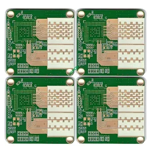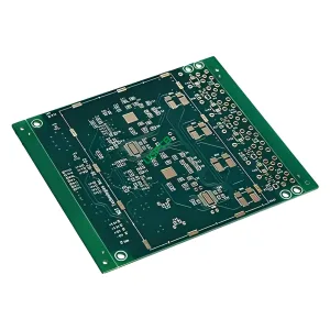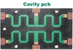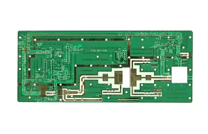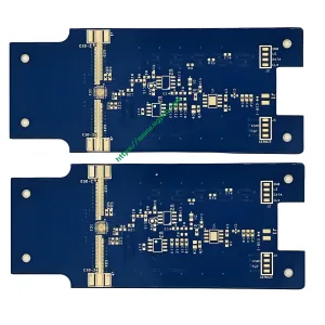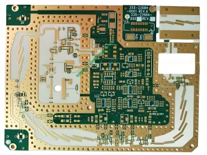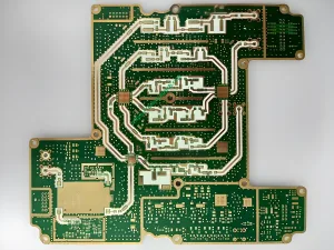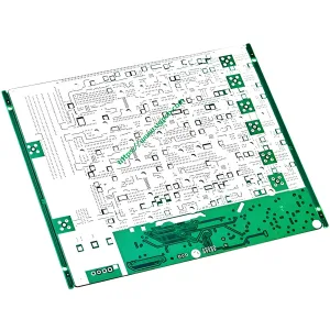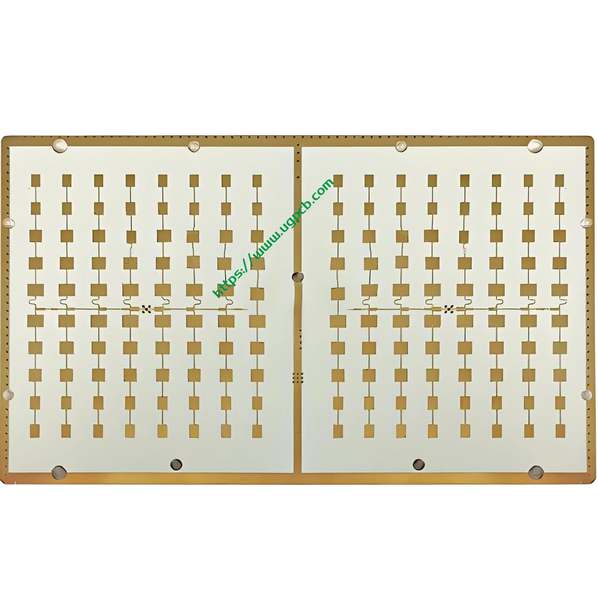
Rogers PCB – The Superior Choice for High-Frequency Microwave Circuits
In the era of rapid technological advancement in 5G communications, رادار الموجة المليمترية, والملاحة عبر الأقمار الصناعية, signal transmission speed and precision have become critical system performance determinants. Rogers high-frequency PCBs offer excellent dielectric constant (DK) يتراوح (2.2–16), ultra-low dissipation factor (ص), and outstanding temperature stability. These properties make them the ideal substrate choice for high-performance RF and microwave circuit designs.
📥 Get a Fast Rogers PCB Quote
أنا. Rogers PCB Overview: Redefining High-Frequency Circuit Performance
روجرز لوحات الدوائر المطبوعة use specialty high-frequency laminates produced by Rogers Corporation. Unlike conventional FR-4 epoxy glass fabric substrates, Rogers PCBs use ceramic-filled polytetrafluoroethylene (PTFE) or ceramic-hydrocarbon composites as the core dielectric. This unique material composition makes them irreplaceable in high-frequency microwave applications.
Market Update: According to the latest 2025 data from the China Electronic Materials Industry Association (CEMIA) and Prismark, China‘s high-frequency circuit board market reached RMB 22.8 مليار, أ 23.2% year-on-year increase from RMB 18.5 مليار في 2024. Products using high-end substrates like Rogers captured over 35% من الإيرادات, driven by emerging applications such as millimeter-wave radar and 1.6T optical modules. The global Rogers PCB market is projected to grow from USD 2.21 مليار في 2024 to USD 3.5 مليار من قبل 2035.
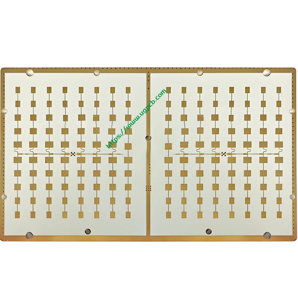
ثانيا. What Is a Rogers PCB? Core Technology Essentials
A Rogers PCB is a printed circuit board manufactured using Rogers Corporation’s specialty high-frequency laminates. مقارنة ب traditional PCBs, Rogers circuit boards offer superior performance in three key dimensions:
1. Low Dielectric Constant and Temperature Stability: Rogers PCB materials have a Dk range of 2.2 ل 16 with an exceptionally low thermal coefficient of dielectric constant (TCDk). على سبيل المثال, RO4350B material has a Dk of 3.48 ±0.05, with a variation of less than 50 ppm/°C across the -50°C to 150°C temperature range. This ensures consistent signal transmission characteristics whether in polar low temperatures or equatorial high-temperature environments.
2. Ultra-Low Dissipation Factor: Rogers materials achieve a Df as low as 0.0004 (لRT/دورويد 5880), far below conventional FR-4‘s 0.02. In 77GHz automotive radar applications, RO3003 material keeps signal attenuation to 1.3dB/inch for 5 mil laminates, significantly improving radar detection accuracy.
3. Excellent Thermo-Mechanical Stability: Rogers high-frequency PCBs combine low moisture absorption (<0.03% typical for PTFE-based materials) with good thermal conductivity (0.50–0.66 W/m·K typical for RO4000 series). This ensures stable performance even in humid and hot environments. In aerospace applications, their low outgassing characteristics meet the demanding requirements of vacuum environments.
Key Parameters at a Glance
| المعلمة | Specification Range |
|---|---|
| نوع المواد | Rogers Ceramic-Filled PCB / Hydrocarbon Composite |
| ثابت العزل الكهربائي (DK) | 2.2 - 16 |
| عدد الطبقة | 1 Layer – Multilayer Hybrid PCB |
| سمك اللوحة النهائية | 0.1mm – 12mm |
| وزن النحاس | 0.5oz – 3oz |
| الانتهاء من السطح | غمر الفضة, يوافق, OSP |
| معيار الجودة | فئة IPC-6012 2 / فصل 3 |
| التطبيقات النموذجية | High-Frequency Rogers Microwave PCB, RF Front-Ends, mmWave Antennas |
ثالثا. Rogers High-Frequency PCB Product Series and Model Selection
UGPCB provides PCB fabrication services covering the full range of Rogers materials. Each series suits different frequency ranges and budget requirements. Below is a detailed breakdown of the four major series:
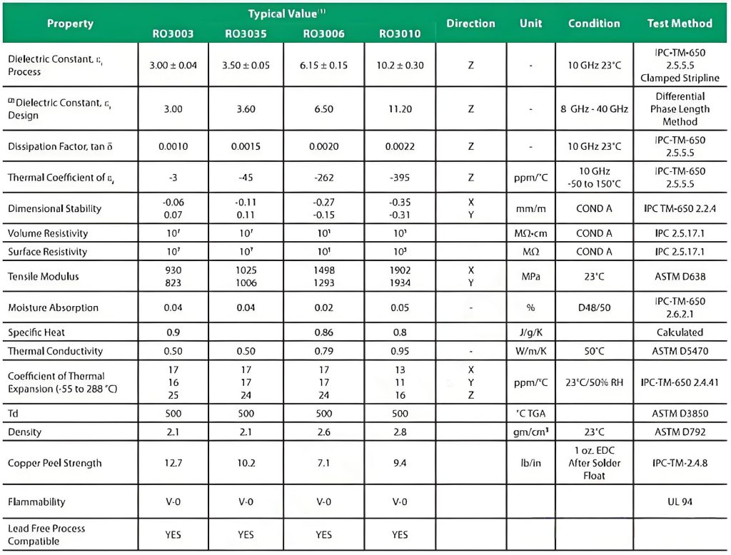
1. RO3000® Series: The Top Choice for Millimeter-Wave Radar
- Representative Models: 3003 ريال عماني, RO3003G2, RO3006, 3010 ريال عماني
- ثابت العزل الكهربائي (DK): 3.0 - 10.2 @ 10 جيجا هرتز
- عامل التبديد (ص): 0.001 - 0.002 @ 10 جيجا هرتز
- المزايا الأساسية: Based on ceramic-filled PTFE, the Dk remains stable over a wide temperature range. 3003 ريال عماني has a Z-axis CTE of 24 ppm/°C and X/Y-axis CTE of 17 جزء في المليون/درجة مئوية, which matches copper foil well, ensuring via reliability under severe thermal cycling. With a Df of 0.0013 at 10GHz for the RO3003, it is one of the lowest insertion loss commercial materials available.
- التطبيقات النموذجية: 77GHz automotive millimeter-wave radar, اتصالات الأقمار الصناعية, RF couplers, هوائيات نظام تحديد المواقع.
2. RO4000® Series: The Perfect Balance of Cost and Performance
- Representative Models: RO4003C, 4350 مليار ريال عماني, RO4835, RO4360G2
- ثابت العزل الكهربائي (DK): 3.38 - 6.15 @ 10 جيجا هرتز
- عامل التبديد (ص): 0.0027 - 0.0040 @ 10 جيجا هرتز
- المزايا الأساسية: These hydrocarbon ceramic composites are fully compatible with standard FR-4 fabrication processes, which significantly reduces manufacturing costs. RO4835 offers ten times the oxidation resistance of 4350 مليار ريال عماني, making it ideal for outdoor base station antennas and high-temperature environments. RO4360G2 features thermal conductivity up to 0.8 W/m·K and a Z-axis CTE as low as 30 جزء في المليون/درجة مئوية, providing excellent heat dissipation in high-power applications.
- التطبيقات النموذجية: 5هوائيات المحطة الأساسية G, RF power amplifiers (السلطة الفلسطينية), المكونات السلبية, point-to-point microwave communications.
3. RT/duroid® 5000/6000 مسلسل: The Industry Benchmark for Extreme Performance
- Representative Models: RT / duroid 5880, 5870, 6002, 6006, 6010إل إم
- ثابت العزل الكهربائي (DK): 1.96 - 10.2 @ 10 جيجا هرتز
- عامل التبديد (ص): منخفضة مثل 0.0009 @ 10 جيجا هرتز (RT5880)
- المزايا الأساسية: Pure PTFE-based materials, recognized as the most stable high-frequency materials in the industry, featuring ultra-low loss and minimal Dk variation with frequency. RT5880 is known for its Dk of 2.20 ±0.02 and Df of 0.0009. RT/DUROID 6010LM, with a Dk of 10.2 ±0.25, is specifically designed for miniaturized circuits requiring a high dielectric constant.
- التطبيقات النموذجية: Satellite communication LNBs, precision phased array radar, millimeter-wave imaging, aerospace electronic systems.
4. TMM® Series: Ideal for High-Temperature, تطبيقات عالية الموثوقية
- Representative Models: TMM3, TMM6, TMM10, TMM13i
- ثابت العزل الكهربائي (DK): 3.27 - 12.85 @ 10 جيجا هرتز
- عامل التبديد (ص): 0.001 - 0.002 @ 10 جيجا هرتز
- المزايا الأساسية: Ceramic-filled thermoset materials with excellent mechanical strength and creep resistance. They offer a maximum operating temperature of 170°C and can be processed using standard PCB fabrication methods.
- التطبيقات النموذجية: Aerospace communication systems, مضخمات الطاقة, هوائيات الصفيف المرحلي, الرادار العسكري.
رابعا. How Rogers PCBs Work at High Frequencies – The Source of Signal Integrity
The superior signal integrity of Rogers PCBs at high frequencies comes from the synergy between material properties and electromagnetic wave propagation principles.
ثابت العزل الكهربائي (DK) وسرعة انتشار الإشارة
The speed of an electromagnetic wave in a dielectric medium is inversely proportional to the square root of the dielectric constant:
الخامس = ج / √εᵣ
where c is the speed of light in a vacuum (~3×10⁸ m/s) and εᵣ is the relative permittivity. For Rogers RT5880 (Dk≈2.2), the signal travels at 67% من سرعة الضوء, significantly faster than the 49% achieved with ordinary FR-4 (Dk≈4.2). Faster propagation speeds mean shorter signal delays and higher data throughput.
التحكم الدقيق في المعاوقة المميزة
Characteristic impedance is a critical parameter in high-frequency circuit design. For a microstrip line, it is approximated by:
ض₀ = 87 / √(εᵣ + 1.41) × لن(5.98ح / (0.8ث + ر))
where h is the dielectric thickness, w هو عرض التتبع, و t هو سمك النحاس. Rogers PCB materials provide exceptional Dk stability across the entire frequency range—for example, RO3003 maintains a Dk of 3.00 ±0.04 at 10GHz—and an extremely low TCDk (<50 جزء في المليون/درجة مئوية). This stability is the foundation for achieving characteristic impedance control within ±5%.
عامل التبديد (ص) and Insertion Loss
Insertion loss increases with frequency and can be expressed as:
α = k × f × √εᵣ × tan δ
where tan δ is the dissipation factor, f is the operating frequency, و k ثابت. عند 77 جيجا هرتز, فر-4 (DF≈0.02) would exhibit insertion losses exceeding 20 ديسيبل/بوصة, making signal transmission nearly impossible. في المقابل, 3003 ريال عماني (Df≈0.0013) achieves an insertion loss of only 1.3dB/inch for 5 mil laminates, which is about 1/15th the attenuation of FR-4. This dramatic difference explains why Rogers PCBs are essential for millimeter-wave radar applications.
📷 Image Suggestion 4: Dk stability curve of Rogers materials across frequency ranges (1GHz to 77GHz)
Image ALT Tag: Rogers PCB dielectric constant stability over frequency range from 1GHz to 77GHz for RO3003 RO4350B and RT5880 materials
V. Broad Applications of Rogers PCBs in Cutting-Edge Fields
Thanks to their excellent high-frequency performance and reliability, Rogers PCBs are widely used in the most demanding technology sectors:
📡 5G Communications and Base Stations: Rogers PCBs are the core substrate material for 5G base station antenna feed networks, وحدات الواجهة الأمامية للترددات اللاسلكية, ومضخمات الطاقة. The RO4000 series’ compatibility with FR-4 processes makes it the top choice for large-scale commercial 5G base stations. RO4835 provides ten times the oxidation resistance of RO4350B, making it dominant in outdoor base station antennas.
🚗 Automotive Electronics and ADAS: With the ADAS (Advanced Driver Assistance System) adoption rate in domestic passenger cars exceeding 61% في 2025, 77GHz millimeter-wave radar has created explosive growth in demand for high-frequency PCBs. Average high-frequency PCB usage per vehicle has quadrupled compared to traditional models, and the market for automotive high-frequency boards continues to grow at over 45% سنويا. 3003 ريال عماني, with its Dk of 3.00 ±0.04 and exceptional stability from -50°C to 150°C, has become the standard material for 77GHz automotive radar.
🛰️ Aerospace and Defense: Under extreme temperature variations and vacuum conditions, Rogers PCBs, with their low moisture absorption and excellent thermo-mechanical stability, are widely used in navigation systems, satellite communication modules, الرادار العسكري, and missile guidance systems. RT / duroid 6000 series materials exhibit a Dk variation of ≤±0.03 at 200°C, ensuring signal consistency throughout the aerospace product‘s entire lifecycle.
🔬 Medical Imaging Equipment: The precise handling of high-frequency signals in MRI and ultrasound diagnostic equipment depends on the stable dielectric constant and ultra-low loss characteristics of Rogers PCBs. The TMM series’ chemical resistance ensures long-term reliability in medical devices.
سادسا. Rogers PCB Structure and Hybrid Design
UGPCB provides complete Rogers PCB structure solutions, from single-layer to multi-layer designs, with extensive engineering experience in multi-layer hybrid laminates.
Hybrid Stackup – The Cost-Effective Choice
Rogers high-frequency materials cost approximately 5 ل 15 times more than standard FR-4. In most volume production projects, UGPCB uses a hybrid Rogers + FR4 stackup solution. This approach ensures excellent RF signal transmission quality while optimizing overall manufacturing costs.
Common Hybrid Stackup Configurations:
1. Top-Layer Rogers + Bottom-Layer FR4 (2+N layers): The top 1–2 layers use Rogers high-frequency material for antennas or RF traces, while the remaining layers use FR4 for digital circuits and power distribution. This configuration is ideal for 5G Active Antenna Units (جامعة العين) and millimeter-wave radar modules.
2. Middle-Layer Rogers Core + Outer FR4 Layers (N+Rogers+N layers): The Rogers material serves as the core signal layer, with FR4 protective layers on top and bottom. This configuration provides excellent rigidity, making it suitable for avionics equipment that requires mechanical strength.
3. Full Rogers Multilayer Boards: These are used only for extreme performance millimeter-wave applications (such as 77GHz phased array radar and 94GHz imaging radar) or high-end research prototypes.
Key Considerations for Hybrid Design:
- Impedance Compensation Design: Using process-aware impedance modeling and TDR scans of process validation boards (PVB), we can build an accurate impedance prediction model and control impedance deviation after hybrid lamination to within ±3%.
- Stackup Symmetry Principle: The multi-layer stackup must be symmetrical about the central plane. Materials and copper layers must be arranged symmetrically to avoid residual stress and board warpage after lamination.
- CTE Matching Management: UGPCB carefully selects prepreg materials and optimizes lamination parameters—using a three-stage ramp heating profile with zone pressure compensation—to control the CTE difference between layers, keeping warpage below 30 µm/m.
سابعا. UGPCB Rogers PCB Manufacturing Process – Quality You Can Trust
UGPCB has a mature, complete Rogers PCB fabrication process. Each step is carefully designed and strictly controlled to ensure that every board meets the rigorous requirements of IPC-6012 Class 2 أو الطبقة 3.
1. Material Selection and Preprocessing
We precisely match the Rogers PCB material type (RO4003C, 4350 مليار ريال عماني, RO5880, إلخ.) to each customer‘s design specifications for Dk, سمك اللوح, وزن النحاس, إلخ. All incoming materials undergo a 100% التفتيش البصري. For PTFE-based Rogers materials, we perform plasma activation pretreatment to increase surface energy above 65 ملي نيوتن / م, ensuring excellent coating adhesion.
2. تصنيع دائرة الطبقة الداخلية
نحن نستخدم التصوير المباشر بالليزر (LDI) معدات to accurately transfer circuit patterns to the Rogers substrate, achieving line width/spacing accuracy down to 1.5 mil with a coefficient of variation as low as 2.8%. بعد النقش, AOI equipment inspects for defects such as nicks and shorts.
3. Lamination – The Core Technology
Lamination is the most critical step for Rogers PCB performance and yield:
- Stackup Design: We calculate precise stackup thicknesses based on impedance requirements and signal integrity simulations. We select the right prepreg between Rogers and FR4 layers to ensure strong interlayer bonding.
- Lamination Parameter Control: A three-stage ramp-up heating profile (1.5درجة مئوية/دقيقة) with zone pressure compensation ensures void-free lamination. We hold a constant temperature at 280°C for 30 minutes with increased edge pressure up to 0.3MPa.
- Void and Warpage Control: A vacuum lamination environment and precise temperature/pressure control eliminate voids. Finished board warpage is held to below 30 µm/m, significantly better than the industry average of 80 µm/m.
4. Drilling and Plated Through-Hole (PTH) تعدين
Rogers ceramic-filled materials are hard, so we use diamond-coated drill bits with feed rates of 1.2–1.8 m/min. A step-drilling process minimizes burrs and edge chipping. Electroless copper deposition forms a uniform conductive layer on the hole wall, followed by electrolytic copper plating to build thickness.
5. Outer Layer Circuit and Surface Finish
We offer three surface finish options based on customer requirements:
- يوافق (الذهب الغمر بالنيكل غير الكهربائي): Excellent solderability and corrosion resistance.
- غمر الفضة: High conductivity and flatness for high-frequency signal transmission.
- OSP (مادة حافظة عضوية قابلة للحام): Economical and environmentally friendly.
6. Final Fabrication, تقتيش, and Testing
- Impedance Testing: We use TDR (قياس الانعكاسات في المجال الزمني) to scan each trace, ensuring a characteristic impedance deviation within ±5%.
- الاختبار الكهربائي: We perform insulation resistance testing per IPC-TM-650 2.5.7 و 100% اختبار مسبار الطيران.
- Reliability Verification: We perform thermal stress testing (solder float, 288°C/10 seconds, 3 دورات) per IPC-6012 Class 3 متطلبات, with void count in hole wall sections limited to ≤1 per coupon.
- التحليل المجهري: A metallographic cross-section microscope inspects hole wall copper thickness and integrity.
ثامنا. Rogers PCB Performance – Quality Assurance Under Authoritative Standards
UGPCB strictly follows industry standards from IPC, ensuring that every board meets or exceeds customer expectations.
IPC-6012 Performance Classes:
- فصل 2 (منتجات إلكترونية مخصصة للخدمة): Suitable for 5G base stations, معدات الاتصالات, and industrial controls that require continuous operation but are not mission-critical. This class has moderate tolerances for defects like voids and microcracks.
- فصل 3 (High-Performance Electronic Products): Required for aerospace, المعدات الطبية, and military systems where failure would have severe consequences. فصل 3 demands an inner layer minimum annular ring of 0.001 بوصة (تقريبا. 25.4 ميكرومتر) and an outer layer minimum of 0.002 بوصة (تقريبا. 50.8 ميكرومتر). After thermal stress testing, hole wall voids must not exceed 13 µm in length.
مؤشرات الأداء الرئيسية (based on Rogers official datasheets and IPC test methods):
| المعلمة | القيمة النموذجية | طريقة الاختبار |
|---|---|---|
| ثابت العزل الكهربائي (DK) @ 10 جيجا هرتز | 2.20 - 16 (varies by type) | IPC-TM-650 2.5.5.5 |
| عامل التبديد (ص) @ 10 جيجا هرتز | 0.0004 - 0.0040 | IPC-TM-650 2.5.5.5 |
| الموصلية الحرارية | 0.50 - 0.66 ث / م · ك (RO4000 series typical) | أستم D5470 / IPC-TM-650 |
| المحور Z CTE | 24 - 50 جزء في المليون/درجة مئوية | IPC-TM-650 2.4.41 |
| امتصاص الرطوبة | <0.03% (على أساس PTFE) ل 0.05% (سلسلة 4000 ريال عماني) | IPC-TM-650 2.6.2.1 |
| قوة عازلة | >31.5 kV/mm typical | ASTM D149 / IPC-TM-650 |
| مقاومة الحجم | >10⁷ ohm·cm @ 500V | IPC-TM-650 2.5.17 |
These values are based on Rogers Corporation datasheets and may vary slightly depending on material type and manufacturing process.
أول 94 تصنيف القابلية للاشتعال: RO4000 series materials are UL 94 V-0 معتمد, meeting the fire safety requirements for electronic products.
الامتثال لـ RoHS: UGPCB‘s Rogers PCB products are fully RoHS compliant, meeting environmental standards for major global markets.
تاسعا. Why Choose UGPCB for Your Rogers PCB Needs?
Hundreds of leading technology companies worldwide choose UGPCB as their Rogers high-frequency PCB supplier. Here are our core advantages:
- Full Material Support: We cover all four major Rogers series (RO3000®, RO4000®, RT/duroid®, TMM®) with Dk from 2.2 ل 16. We also offer prepreg and bondply materials for multilayer builds.
- Professional Hybrid Lamination Capability: We specialize in Rogers + FR4 multi-layer hybrid lamination, reducing material costs by 30–40% compared to all-Rogers structures while maintaining excellent signal isolation between RF and digital sections.
- التحكم في المعاوقة بدقة عالية: Using TDR impedance testing and process-aware modeling, we hold characteristic impedance to within ±3% of the target, meeting the stringent requirements of PCIe 5.0 and high-speed SerDes.
- Strict Process Control: We maintain an ISO 9001 نظام إدارة الجودة with full traceability from raw material receiving to finished product shipping. We monitor key process parameters in real-time, achieving a Cpk ≥1.33.
- Strong Engineering Support: Our experienced RF engineering team provides DFM review, impedance stackup calculation, and rapid prototyping services. We turn customer design concepts into production-ready products quickly.
- Extensive Production Experience: لقد تسلمنا 10,000 Rogers PCB designs, ranging from simple 2-layer boards to complex 24-layer hybrid stacks, with minimum line width/spacing down to 1.5 ميل.
X. الأسئلة المتداولة (التعليمات)
س1: How much more does a Rogers PCB cost compared to FR-4?
أ: Rogers materials cost about 3 ل 15 times more than FR-4, depending on the specific type and thickness. RO4000 series is about 3–4 times more, RO3000 series is about 6–7 times more, وRT/الدوريويد 5880 is about 8–10 times more. لكن, hybrid stackup designs can reduce overall cost by 30–40%, achieving the best balance of performance and cost.
Q2: How do I choose the right Rogers series for my project?
أ: It depends on your operating frequency and performance requirements:
- Up to 40GHz with cost sensitivity → RO4003C
- Lead-free assembly or automotive applications → RO4350B
- 77GHz millimeter-wave radar → RO3003
- Ultra-low loss up to 100GHz → RT5880
- High dielectric constant for miniaturization → RT6010LM or TMM10
س3: What is the minimum line width/spacing UGPCB can achieve on Rogers PCBs?
أ: UGPCB currently supports a minimum line width/spacing of 1.5 ميل (0.038مم) and a minimum via diameter of 6 ميل (0.15مم).
س 4: Can Rogers PCBs be finished with ENIG?
أ: نعم. UGPCB offers ENIG, غمر الفضة, and OSP surface finishes to meet different requirements for solderability, مقاومة التآكل, and signal loss. PTFE-based boards receive plasma activation pretreatment to ensure good coating adhesion.
س5: What is the maximum layer count for Rogers PCBs?
أ: يدعم UGPCB 1 ل 20+ layers for all-Rogers and hybrid multi-layer PCBs. For conventional hybrid stackups (top-layer Rogers + bottom-layer FR4), we can support designs with 16 layers or more.
الحادي عشر. Why UGPCB Is Your Trusted Rogers PCB Supplier
UGPCB is a leading high-frequency الشركة المصنعة لثنائي الفينيل متعدد الكلور في الصين, specializing in Rogers PCBs, high-frequency hybrid PCBs, and microwave RF PCBs. Our engineering team has an average of over 10 years of high-frequency board production experience. We have delivered more than 10,000 Rogers PCB designs to customers across five continents in telecommunications, إلكترونيات السيارات, والفضاء.
التزامنا:
✅ الدعم الفني الاحترافي: Free DFM engineering review, impedance stackup calculation, and rapid cost estimation
✅ Flexible Lead Times: 3–5 days for quick-turn 2-layer prototypes, 7–10 days for 4–8 layer boards, 15–20 days for volume orders
✅ ضمان الجودة: 100% اختبار كهربائي, تفتيش المنظمة العربية للتصنيع, microsection sampling, and TDR impedance testing
✅ Full Traceability: Complete production records and test reports retained for each batch
✅ خدمة وقفة واحدة: From Gerber file to finished تجميع PCBA, اختبار, and burn-in, with no need to manage multiple vendors
Contact us today for your Rogers PCB solution!
Whether you need rapid prototype validation or volume production, UGPCB is your trusted partner for Rogers high-frequency PCBs. Our technical experts are ready to provide the best solution for your project.
📞هاتف: Call us for a dedicated quote
📧بريد إلكتروني: sales@ugpcb.com
🌐موقع إلكتروني: www.ugpcb.com
📝الاستفسار عبر الإنترنت: Click below to upload Gerber files and receive a quote within 5 دقائق
🚀 Upload Gerber Files for Free Engineering Review + Fast Quote
Please provide the following information for an accurate quote:
- نوع المواد (على سبيل المثال, 4350 مليار ريال عماني / RO4003C / RO5880)
- Finished Board Thickness and Tolerance
- Layer Count and Stackup Structure
- وزن النحاس (على سبيل المثال, 1 أوقية / 2 أوقية / 3 أوقية)
- الانتهاء من السطح (يوافق / غمر الفضة / OSP)
- Quantity and Lead Time Requirements