

In the reliability engineering of electronic products, two plating failure modes lurk like invisible assassins. They hide in the microscopic details of PCB (Circuiti stampati) E PCBA (Printed Circuit Board Assemblies), waiting to cause catastrophic failures. These modes are tin whiskers and creeping corrosion. From the loss of a $250 million communications satellite to the false triggering of nuclear power plant alarms, numerous engineering case studies prove one truth: plating reliability is the non-negotiable foundation for the long-term stable operation of electronic products. This article provides a deep technical analysis for Progettazione di circuiti stampati, produzione, and reliability engineers. It covers failure mechanisms, classic case studies, influencing factors, and mitigation measures.
1. Tin Whiskers: Conductive “Peli” with Micron Diameters and Kilometer-Long Risks
1.1 Definition and Characteristics
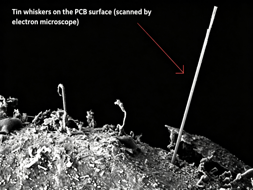
Tin whiskers are fine, needle-like single-crystal tin protrusions. They grow spontaneously on the surface of pure tin or tin alloy platings. Their diameters typically range from 1 A 10 μm, making them invisible to the naked eye. Tuttavia, their lengths can reach several millimeters. In extreme cases, they can grow to over25 mm. Once a whisker becomes long enough to bridge adjacent conductors on a PCB—such as pads, perni, or traces—it can causelow-impedance short circuits or arc discharges. The danger is especially severe in the low-pressure environments of aerospace applications.
1.2 Classic Engineering Case Studies: From the F-15 Fighter to the Galaxy 4 Satellite
The destructive power of tin whiskers is no exaggeration. NASA has long tracked and documented numerous major failure incidents caused by tin whiskers:
- 1986, U.S. Air Force F-15 Fighter: The radar equipment experienced intermittent failures. Vibration in the cockpit caused the tin whiskers to shift position continuously. This made the short circuits come and go, greatly increasing the difficulty of fault localization.
- 1987 to present, Nuclear Power Plants: At least seven nuclear power plant shutdowns have been attributed to false signal outputs from alarm system circuits caused by tin whiskers. These false signals led systems to incorrectly judge reactor status.
- 1998, PanAmSat Galaxy 4 Communications Satellite: This is one of the most famous failure cases in the industry. The Galaxy 4 satellitare, worth $250 milione and serving tens of millions of users in North America, was lost permanently due to the failure of its main processor. Investigations confirmed that the culprit was an electrical short caused by tin whiskers. Statistics show that from 1998 to the present, tin whiskers have caused a cumulative total of 11 control system failures on commercial satellites in orbit. Four satellites were lost completely.
- 2006, Space Shuttle: During engine tests, the system reported false engine failure signals due to tin whiskers. This nearly triggered an orbital deviation maneuver.
1.3 Growth Mechanisms and Mitigation Strategies
The primary driving force behind tin whisker growth iscompressive residual stress within the plating layer. This stress can originate from various sources: the uneven growth of Cu-Sn intermetallic compounds (such as Cu₆Sn₅) at the interface, bath chemistry imbalances, mechanical external forces, or thermal cycling mismatches.
Based on this understanding, the industry has developed a mature set ofmitigation strategies. These methods are incorporated into international standards such asJEDEC JESD201 (Environmental Acceptance Requirements) EJEDEC/IPC JP002 (Whisker Theory and Mitigation Practices Guideline):
- Alloying: Adding elements like Pb (lead) to the tin plating is a proven method validated by NASA. After confirming the risks of pure tin plating, NASA explicitly requires the addition of a small amount of lead to tin platings on critical components.
- Underlayer Barrier: Depositing a In (nickel) layer on the copper lead frame as a diffusion barrier effectively prevents the rapid formation of Cu-Sn intermetallic compounds. This relieves compressive stress and inhibits whisker growth at room temperature.
- Bath Chemistry and Heat Treatment: Strictly monitoring additives during the tin plating process prevents stress from bath imbalances. Inoltre, UN 150° C. high-temperature bake effectively releases internal stress in the plating, altering the kinetics of whisker growth.
2. Creeping Corrosion: The Quietly Spreading Black “Plague”
If tin whiskers are instantaneous “short-circuit assassins,” then creeping corrosion is a slow but deadly “black plague.”
2.1 Definition and Mechanism
Creeping corrosion specifically refers to the reaction ofexposed Cu surfaces with sulfur-bearing environments (H₂S, SO₂, elemental sulfur, ecc.). This reaction generatesblack copper sulfides (such as Cu₂S). These corrosion products possessextremely high surface mobility. Driven by concentration gradients, they continuouslymigrate and creep across the surface of the PCB solder mask, forming web-like structures.
This process follows thedissolution/diffusion/deposition mechanism:
- Copper oxides are insoluble in water, but copper sulfides and chlorides are water-soluble. They diffuse rapidly with the aid of moisture (a water film).
- Copper sulfides have semiconductor properties. Their insulation resistance can drop sharply from 10 MΩ to 1 OH as concentrations accumulate. This eventually leads to short circuits between adjacent pads or vias.
2.2 Key Influencing Factors and Authoritative Data
(1) Umidità: An Exponential Accelerator
Humidity is the most critical accelerating factor for creeping corrosion. Research byPing Zhao and colleagues shows that the creeping corrosion rate has anexponential relationship with humidity.Craig Hillman and his team found in mixed flowing gas experiments that the corrosion rate increases in aparabolic fashion as relative humidity rises. For copper, when the relative humidity increases from 60% RH to 80% RH, the corrosion rate increases by a factor of 3.6.
(2) Corrosive Gases: Overlooked Environmental Killers
Corrosive gases in the atmosphere provide the material basis for creeping corrosion. Basato su 1.5 years of monitoring data from large computers in six U.S. facilities and 6-month exposure test data from Tokyo, Giappone, the key pollutant gases and their allowable concentration limits are as follows:
| Pollutant Gas | Indoor Concentration (μg/m³) | Accumulation Rate (μg/m²) | Allowable Concentration (μg/m³) | Primary Materials Affected |
|---|---|---|---|---|
| SO₂ | 1~40 | 5.2~16.2 | 71 | All metals, especially Ni-plated |
| NO₂ | 3~60 | 28.7~58.7 | 82 | Cu, Cu alloys |
| H₂S | 0.2~1 | 0.04~0.24 | 3 | Ag, Cu |
| HCl | 0.08~0.3 | 1.5~4.7 | 3 | Almost all metals |
| Cl₂ | 0.004~0.015 | - | 0.4 | Cu |
(Origine dati: U.S. 6-site indoor monitoring and Tokyo exposure tests)
(3) PCB Substrate and Surface Finish: Material Selection Determines Destiny
Different substrates and surface finishes show significant differences in resistance to creeping corrosion:
- Substrate Comparison (Conrad study, dry/wet H₂S atmosphere): Brass exhibits the best resistance to creeping corrosion, Mentre CuNi performs the worst.
- Surface Finish Comparison (joint evaluation by Alcatel-Lucent, Dell, e altri): Sanguinare (Livellamento della saldatura ad aria calda) E Im-Sn (Stagno per immersione) show the best Resistenza alla corrosione. OSP (Conservante organico di saldabilità) E Essere d'accordo (Oro per immersione in nichel chimico) show moderate prestazione. Im-Ag (Argento immersione) shows the poorest Resistenza alla corrosione.
2.3 Typical Failure Morphologies
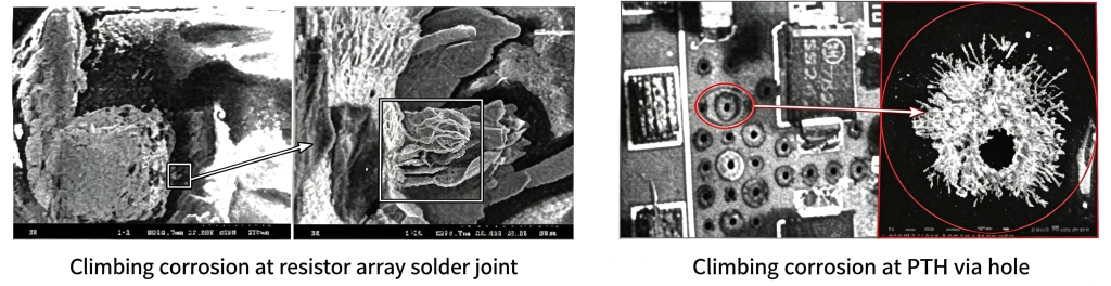
In practical failure analysis, creeping corrosion often presents two typical morphologies:
- Resistor Network Solder Joint Corrosion: Black sulfide corrosion products spread around the solder joints, eventually causing short circuits between adjacent joints.
- PTH (Foro passante placcato) Corrosion: The copper surface inside the plated through-hole undergoes sulfidation. The corrosion products migrate along the hole wall, severely compromising the electrical connection reliability of the via.
3. Prevention and Detection: Building a Reliable PCB/PCBA Defense Line
3.1 Prevention Measures
- Material Optimization: Prioritize surface finishes with strong resistance to creeping corrosion, ad esempio HASL or Im-Sn. Per prodotti ad alta affidabilità, consider Essere d'accordo combined with via filling processes.
- Environmental Control: Strictly control the concentration of corrosive gases in the operating environment. Keep H₂S concentration below 3 μg/m³ and relative humidity sotto 60% RH.
- Tin Whisker Mitigation: Deposit a Ni barrier layer on copper leads, or use Pb-containing tin alloy platings. Strictly implement the temperature cycling tests (-55/85° C., 3000 cicli) specified in JEDEC JESD201 for tin whisker risk assessment.
- Rivestimento conforme: Apply a conformal coating on the PCBA surface to physically isolate it from corrosive gases.
3.2 Detection Methods
| Detection Method | Scenario applicativo |
|---|---|
| SEM/EDS | Observe the micro-morphology and elemental composition of whiskers and corrosion products |
| Ion Chromatography (CIRCUITO INTEGRATO) | Detect corrosive ionic contaminants remaining on the PCB surface |
| X-Ray Inspection | Non-destructively detect internal structural defects in PTH vias |
| Metallographic Cross-Sectioning | Visually present the migration paths and depth of corrosion products |
For bulk PCB/PCBA procurement and custom requirements, we recommend selecting a Fornitore di PCB with certification capabilities for IEC 62483 (Tin Whisker Environmental Acceptance Testing) E ASTM B845 (Mixed Flowing Gas Corrosion Testing). To obtain a professional citazione or to consult on high-reliability PCB/PCBA solutions, please contact our technical team. We are ready to help you buy the right products for your application.
Dichiarazione dell'origine dei dati
The data and case studies cited in this article are primarily sourced from the following authoritative organizations and standards:
- NASA (National Aeronautics and Space Administration) Tin Whisker Failure Case Reports
- JEDEC Standard JESD201A - Environmental Acceptance Requirements for Tin Whisker Susceptibility of Tin and Tin Alloy Surface Finishes
- JEDEC/IPC Joint Standard JP002 - Current Tin Whiskers Theory and Mitigation Practices Guideline
- JEDEC Metodo di prova JESD22-A121A - Test Method for Measuring Whisker Growth on Tin and Tin Alloy Surface Finishes
- IEC 62483 - Environmental acceptance requirements for tin whisker susceptibility of tin and tin alloy surface finishes on semiconductor devices
- ASTM B845 - Standard Guide for Mixed Flowing Gas (MFG) Tests for Electrical Contacts
- iNEMI (International Electronics Manufacturing Initiative) Tin Whisker Research Project reports and Creeping Corrosion research reports
- U.S. 6-site indoor environmental monitoring data and Tokyo, Japan exposure test data
