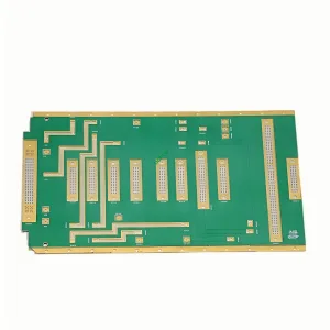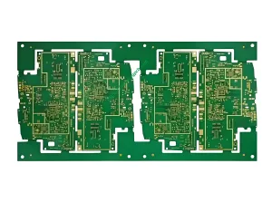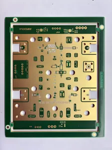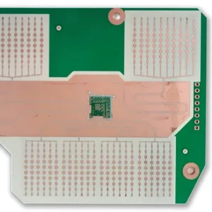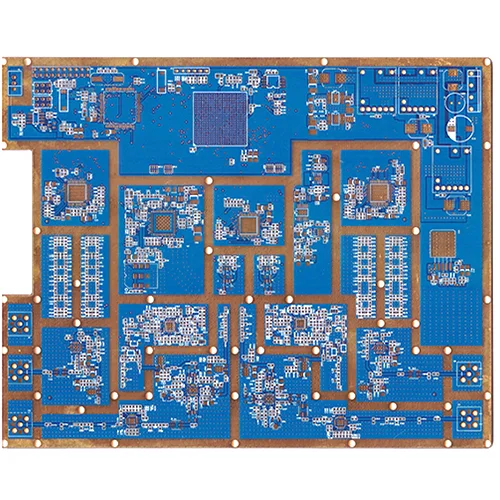
1. Panoramica del prodotto: Cos'è un PCB ibrido ad alta frequenza?
UN PCB ibrido ad alta frequenza integra i laminati ad alta frequenza Rogers RO4350B con materiali FR4 standard in un unico prodotto pannello multistrato attraverso la laminazione di precisione.
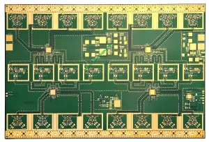
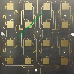
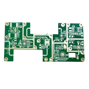
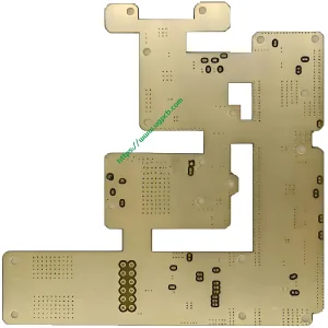
UGPCB offre a12-PCB ibrido ad alta frequenza a strati costruito con Rogers RO4350B e FR4. Lo spessore del pannello finito è 1,6 mm con rame finito 1OZ. L'impedenza caratteristica è controllata con precisione a 50Ω. Questa scheda serve applicazioni RF/microonde e a segnale misto che richiedono prestazioni ad alta frequenza ed efficienza dei costi.
Perché scegliere un design ibrido? Nelle stazioni base 5G, radar automobilistico, e moduli di comunicazione ad alta velocità, I circuiti RF necessitano di materiali Rogers a bassa perdita per l'integrità del segnale. Circuiti di controllo digitale, gestione dell'energia, e le interfacce funzionano perfettamente con FR4 standard a costi molto inferiori. Una tavola Rogers completa costa 3 A 8 volte più di FR4. Una scheda FR4 completa non può soddisfare i requisiti di prestazioni RF. IL PCB ibrido ad alta frequenza raggiunge l'equilibrio ottimale tra prestazioni e costi.
2. Classificazione dei prodotti e conformità agli standard
2.1 Classificazione per combinazione di materiali
Questo prodotto è unPCB laminato ibrido – combinando Rogers RO4350B (strati ad alta frequenza) con FR4 (livelli digitali/di potenza) tramite pressatura di precisione. Sotto IPC-4101, Rogers RO4350B è un laminato rinforzato con vetro caricato con idrocarburi/ceramica. FR4 è un laminato rivestito in rame con tessuto di vetro tessuto epossidico ignifugo.
2.2 Classificazione per classe di prestazione IPC-6012
Per IPC-6012, questo consiglio si riunisceClasse 2 (prodotti elettronici di servizio dedicato) EClasse 3 (apparecchiature elettroniche ad alta affidabilità) Requisiti.
2.3 Classificazione per gamma di frequenza
Questo è unPCB frequenza RF/microonde. Lo strato Rogers RO4350B mantiene una costante dielettrica stabile di 3,48±0,05 a 10 GHz, adatto per progetti con frequenza da 500 MHz a onde millimetriche.
3. Materiali principali e parametri chiave di prestazione
3.1 Rogers RO4350B – Il “Gold Standard” per gli strati ad alta frequenza
Rogers RO4350B è un sistema brevettato di resine idrocarburiche con riempitivo ceramico, rinforzato con tessuto di vetro. I principali vantaggi includono:
- Costante dielettrica (Non so): 3.48 ± 0.05 @ 10ghz (valore del processo), 3.66 (valore progettuale). FR4 ha tipicamente ±5% a 10% Variazione Dk. RO4350B offre solo una tolleranza di ±1,4%., fornendo una solida base per un controllo preciso dell'impedenza.
- Fattore di dissipazione (Df): 0.0037 @ 10GHz – significativamente inferiore a FR4, garantendo la trasmissione del segnale ad alta frequenza a bassa perdita.
- Conducibilità termica: 0.69 W/m·K a 50°C (ASTM D5470).
- Resistività al volume: 1.2×10¹⁰ MΩ·cm (IPC-TM-650 2.5.17.1).
- Classificazione ignifuga: UL 94 V-0.
3.2 FR4 – La scelta economicamente vantaggiosa per i livelli digitale e di potenza
FR4 è un laminato standard in tessuto di vetro intrecciato con resina epossidica ignifuga. Offre costi contenuti, elaborazione matura, ed elevata resistenza meccanica. Funziona bene per i circuiti digitali, distribuzione di potenza, e strati di terra.
3.3 12-Struttura di stackup ibrido a strati
Questo prodotto utilizza a12-impilamento ibrido a strati. Gli strati esterni e gli strati critici del segnale RF utilizzano core Rogers RO4350B. Gli strati interni utilizzano core FR4 per l'alimentazione, terra, e segnali digitali a bassa velocità. Lo spessore totale del pannello è di 1,6 mm. Lo spessore del rame finito è 1 OZ (35μm).
3.4 Riepilogo dei parametri chiave delle prestazioni
| Parametro | Specifica | Norma di prova/riferimento |
|---|---|---|
| Laminato | Rogers RO4350B + FR4 | - |
| Conta dei strati | 12 strati | - |
| Spessore del pannello finito | 1.6mm | IPC-6012 |
| Spessore di rame finito | 1OZ (35μm) | IPC-6012 |
| Impedenza caratteristica | 50OH | IPC-2141 / IPC-2251 |
| Spessore dielettrico | 0.508mm | - |
| Costante dielettrica (Non so) | 3.48 ± 0.05 @ 10ghz | Scheda tecnica Rogers RO4350B |
| Conducibilità termica | 0.69 W/m·K a 50°C | ASTM D5470 |
| Classificazione ignifuga | UL 94 V-0 | UL 94 |
| Resistività al volume | 1.2×10¹⁰ MΩ·cm | IPC-TM-650 2.5.17.1 |
4. Considerazioni di progettazione: Quattro principi fondamentali per i PCB ibridi ad alta frequenza
4.1 Controllo dell'impedenza: raggiungimento del target di 50Ω
Controllo dell'impedenza è centrale per PCB ad alta frequenza progetto. Lo standard 50Ω è l'impedenza più utilizzata nei sistemi RF. Questo prodotto mantiene l'impedenza a 50OH per garantire il massimo trasferimento di potenza e la minima riflessione del segnale.
La precisione dell'impedenza dipende dallo spessore del dielettrico, costante dielettrica, e larghezza della traccia. La tolleranza Dk di ±1,4% di RO4350B offre un chiaro vantaggio rispetto alla tolleranza di ±5% di FR4 10% variazione. Una nota critica: perché RO4350B ha un Dk inferiore, le larghezze delle tracce del segnale sugli strati Rogers devono essere approssimative 10% A 15% più largo rispetto agli strati FR4 per i progetti da 50Ω. Inoltre, una variazione di ±0,5 mil nello spessore dielettrico può spostare l'impedenza di circa ±2 Ω su una linea a microstrip Rogers da 10 mil, rendendo essenziale il controllo preciso dello spessore.
4.2 Progettazione stackup: bilanciamento di prestazioni e costi
La progettazione dello stackup influisce sull'integrità del segnale, Integrità del potere, Performance EMC, e complessità del controllo dell'impedenza. Questo stackup a 12 strati segue questi principi:
- Strati di segnale RF sono posizionati sugli strati esterni del Rogers RO4350B utilizzando strutture a microstriscia per ridurre al minimo la perdita di trasmissione.
- Strati di terra e di potenza sono posizionati su strati FR4, fornendo piani di riferimento stabili.
- Simmetria degli strati mantiene l'equilibrio meccanico per prevenire deformazioni.
- Compatibilità dei materiali – RO4350B può essere elaborato utilizzando gli stessi metodi di FR4, eliminando i trattamenti speciali richiesti per i materiali a base PTFE.
4.3 Gestione termica – 0.69 W/m·K Dissipazione del calore
Questo prodotto raggiunge 0.69 W/m · k conducibilità termica. In PCB gestione termica, conduttività termica k (W/m · k) misura l'efficienza con cui un materiale trasferisce il calore. RO4350B 0.69 W/m·K supera significativamente lo standard FR4 (circa 0.25 A 0.3 W/m · k), consentendo una dissipazione del calore più efficace dai dispositivi RF ad alta potenza.
4.4 Stabilità dimensionale – Il basso CTE garantisce affidabilità
Coefficiente di dilatazione termica dell'asse Z del RO4350B (Cte) È 32 ppm/° C. (-55da °C a 288 °C). Questo corrisponde strettamente al CTE del rame (circa 17 ppm/° C.), garantendo il foro passante placcato (PTH) affidabilità in caso di cicli termici. I valori CTE degli assi X e Y lo sono 10 ppm/°C e 12 ppm/°C rispettivamente. La temperatura di transizione del vetro (Tg) supera i 280°C, mantenendo caratteristiche di espansione stabili a tutte le temperature di lavorazione.
5. Principio di lavoro: Come viaggiano i segnali ad alta frequenza in un PCB ibrido?
Nei circuiti ad alta frequenza, i segnali si propagano come onde elettromagnetiche anziché semplici livelli logici “0” e “1”.. ILPCB ibrido ad alta frequenza opera attraverso diversi meccanismi:
Trasmissione del segnale: I segnali ad alta frequenza viaggiano in strutture a microstriscia o stripline sullo strato RO4350B. Il basso Dk del RO4350B (3.48) e basso Df (0.0037) garantiscono che i segnali si propaghino con una perdita di inserzione minima.
Corrispondenza di impedenza: Controllo preciso della larghezza della traccia, spessore dielettrico, e la costante dielettrica imposta l'impedenza caratteristica a 50 Ω. Questo corrisponde alla fonte, linea di trasmissione, e carico, massimizzando il trasferimento di potenza e riducendo al minimo la riflessione del segnale.
Interconnessione tra strati: Strati di segnale ad alta frequenza (Rogers) connettersi a livelli digitali/di potenza (FR4) attraverso fori passanti placcati (PTH). CTE basso sull'asse Z del RO4350B (32 ppm/° C.) garantisce l'affidabilità del PTH durante il ciclo termico.
Gestione termica: Il calore proveniente dai dispositivi RF ad alta potenza conduce attraverso lo strato RO4350B (0.69 W/m · k) agli strati FR4 e alle strutture esterne di dissipazione del calore, mantenendo i dispositivi a temperature operative sicure.
6. Processo di produzione: Dai materiali al pannello ibrido a 12 strati finito
6.1 Ispezione del materiale in entrata
Ispezionare i nuclei Rogers RO4350B e FR4. Verificare la costante dielettrica, spessore, qualità della lamina di rame, e altri parametri rispetto ai requisiti della scheda tecnica IPC-4101 e Rogers.
6.2 Fabbricazione di circuiti a strato interno
Trasferimento del modello del circuito di processo, Incisione, e ispezione AOI sugli strati interni di FR4 (per potenza e terra).
6.3 Trattamento all'ossido bruno
Applicare un trattamento con ossido marrone alle superfici in rame dello strato interno per migliorare l'adesione dello strato.
6.4 Layup e laminazione
Questo è il passaggio più criticograzie al PCB ibrido produzione:
- Impila i core Rogers, Nuclei FR4, e preimpregnato secondo lo stackup a 12 strati progettato.
- Utilizzare la laminazione a gradini per prevenire stress e distorsioni dimensionali causate dalle differenze CTE tra Rogers e FR4.
- Ottimizza la selezione dei preimpregnati (per esempio., preimpregnato a basso flusso) e parametri di laminazione per ridurre al minimo lo stress tra gli strati.
6.5 Perforazione e Desmear
Eseguire forature meccaniche e forature laser (per vie cieche/interrate, se necessario). Seguire con la desmear e la preparazione per la metallizzazione dei fori.
6.6 Metallizzazione e placcatura dei fori
Applicare la deposizione chimica di rame e la placcatura in rame elettrolitico per raggiungere 1OZ (35μm) spessore rame finito.
6.7 Fabbricazione del circuito dello strato esterno
Crea tracce di segnali RF sugli strati esterni di Rogers. Controllare rigorosamente le larghezze della traccia per garantire una precisione di impedenza di 50 Ω.
6.8 Maschera di saldatura e finitura superficiale
Applicare l'inchiostro della maschera di saldatura e la finitura superficiale (per esempio., Essere d'accordo) per garantire saldabilità e resistenza all'ossidazione.
6.9 Test elettrici e ispezione finale
Eseguire 100% test elettrici (compresi test di impedenza e test di continuità). Effettuare un'ispezione visiva, misurazione dimensionale, e campionamento dell'affidabilità.
7. Vantaggi prestazionali: Perché scegliere il PCB ibrido ad alta frequenza a 12 strati di UGPCB?
7.1 Prestazioni superiori ad alta frequenza
RO4350B fornisce Dk = 3,48±0,05 a 10 GHz e Df = 0.0037 @ 10ghz. Queste proprietà garantiscono perdite ridotte, trasmissione del segnale a bassa dispersione da 500 MHz alle frequenze delle onde millimetriche.
7.2 Controllo preciso dell'impedenza da 50 Ω
La tolleranza Dk di ±1,4%., combinato con un preciso controllo dello spessore dielettrico, consente un'impedenza caratteristica di 50Ω ad alta precisione, soddisfacendo i requisiti di adattamento dell'impedenza dei sistemi RF.
7.3 Eccellente rapporto costo-prestazioni
Rispetto ad una soluzione Rogers completa, ILSoluzione ibrida Rogers-FR4 risparmia circa 60% A 70% nei costi dei materiali offrendo prestazioni RF significativamente migliori rispetto a un design FR4 completo.
7.4 Prestazioni meccaniche e termiche affidabili
- UL 94 V-0 classificazione ignifuga
- CTE dell'asse Z di soli 32 ppm/° C.
- Tg > 280°C
- Conduttività termica di 0.69 W/m · k
7.5 Compatibile con l'elaborazione FR4
RO4350B può essere lavorato utilizzando gli stessi metodi dell'FR4 standard. Non sono richiesti trattamenti speciali o procedure di manipolazione, riducendo i costi di produzione e i tempi di consegna.
8. Applicazioni tipiche
8.1 5Stazioni base di comunicazione G
Array di antenne e front-end RF (amplificatori di potenza, amplificatori a basso rumore) richiedono strati RO4350B per connessioni RF a bassa perdita. I processori in banda base e le interfacce digitali possono essere posizionati sugli strati FR4.
8.2 Radar automobilistico a onde millimetriche (77GHz)
Le reti di alimentazione tra le antenne di trasmissione/ricezione e i chip del ricetrasmettitore utilizzano materiali Rogers per una precisa coerenza di fase. I controller radar e le interfacce bus CAN utilizzano livelli FR4.
8.3 Comunicazioni satellitari e trasmissione punto a punto a microonde
Le applicazioni includono antenne per stazioni base cellulari e amplificatori di potenza, microonde punto a punto (P2P) collegamenti, e blocco satellitare a basso rumore diretto a casa (LNB) downconverter.
8.4 Moduli ottici ad alta velocità e comunicazioni cablate
Nelle schede driver del modulo ottico 400G, coppie differenziali SerDes ad alta velocità (≥56 Gbps PAM4) richiedono substrati a bassa perdita per mantenere la qualità del diagramma a occhio. La logica FPGA e la memoria DDR possono utilizzare FR4.
8.5 RFID e rilevamento wireless
Le applicazioni includono tag RFID, sistemi di acquisizione dati wireless, telecomandi senza fili, e sistemi di telemetria.
9. Perché scegliere UGPCB?
UGPCB ha una vasta esperienza nelle proprietà dei materiali ad alta frequenza e nell'elaborazione ibrida, che copre il controllo di processo, placcatura di rame, schemi di laminazione, Tolleranze traccia RF, e controllo dei parametri di impedenza. Ci impegniamo a:
- ✅ 100% test elettrici (compreso il test di impedenza)
- ✅ Rispetto rigoroso degli standard IPC-6012 e IPC-4101
- ✅ Tracciabilità completa della qualità del processo
- ✅ Team di ingegneri professionisti che fornisce DFM (Progettazione per la produzione) supporto

10. Richiedi ora: ottieni la tua soluzione personalizzata
UGPCB12-PCB ibrido ad alta frequenza Rogers RO4350B+FR4 a strati è la soluzione ottimale per le comunicazioni 5G, radar automobilistico, comunicazioni satellitari, e moduli ottici ad alta velocità: bilanciano prestazioni e costi.
📧Invia la tua richiesta adesso. Il nostro team di ingegneri PCB RF risponderà entro 24 ore con:
- Proposte di progettazione di stackup personalizzate
- Calcoli precisi del controllo dell'impedenza da 50Ω
- Prezzi competitivi in termini di volumi
- Raccomandazioni per l'ottimizzazione della producibilità DFM
Rendi UGPCB il tuo partner di fiducia per progetti PCB ibridi ad alta frequenza!