

IO. Panoramica del prodotto: PCB di precisione progettato per apparecchiature estetiche
Lo strumento di depilazione laser si basa su un sistema di controllo principale. Questo sistema impone la sicurezza, stabilità, e l’efficacia complessiva del trattamento. Al centro di questo sistema c'è ilPCB dello strumento per la depilazione laser. Questa componente è tutt’altro che banale.
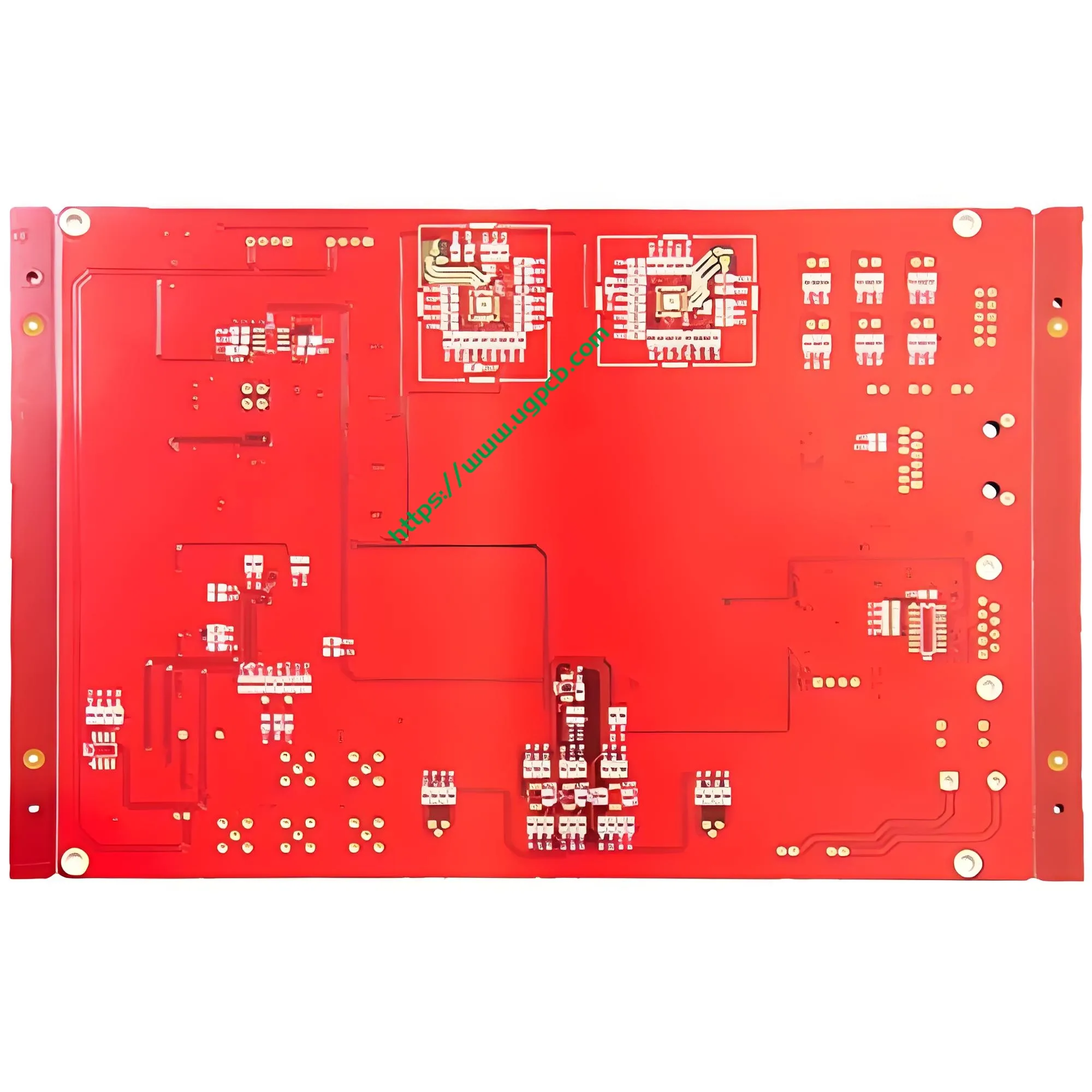
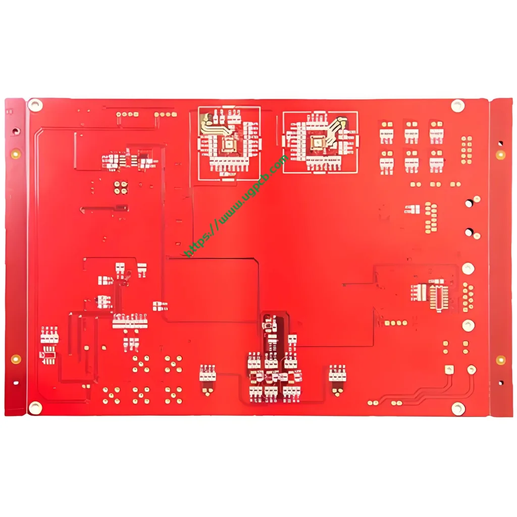
UGPCB presenta acircuito stampato rigido a doppio strato proprio per questo scopo. Produciamo questa tavola utilizzando un laminato epossidico rinforzato con vetro FR4 di alta qualità. Lo spessore del pannello misura 1,0 mm. Le sue dimensioni compatte sono 53.68 x 37,5 mm. Adattiamo queste specifiche specificamente per i vincoli di spazio interno dei moderni dispositivi laser portatili e professionali.
Questo PCB supporta entrambi Luce pulsata intensa IPL E laser a diodi sistemi di depilazione. Garantisce collegamenti elettrici stabili e una trasmissione affidabile del segnale. Un superiore PCB (Gruppo a circuito stampato) costituisce la base stessa di apparecchiature estetiche ad alte prestazioni. UGPCB è specializzato nella fornitura di alta affidabilità, circuiti stampati ad alta precisione per i produttori globali di dispositivi di bellezza.
Ii. Definizione del prodotto: Che cos'è un PCB per uno strumento di depilazione laser?
UNPCB dello strumento per la depilazione laser è un circuito stampato dedicato. Gestisce le funzioni principali come la distribuzione dell'energia, controllo del driver laser, monitoraggio della temperatura, e l'interazione dell'interfaccia utente.
Consideratelo come il sistema nervoso centrale del dispositivo. Canalizza accuratamente l'energia elettrica dalla batteria al generatore laser. Monitora contemporaneamente la temperatura del sistema, regola i livelli di energia, ed elabora gli input dei pulsanti.
Tecnicamente, questo prodotto è una doppia faccia, PCB rigido con foro passante placcato. Utilizza materiale FR4. Secondo IPC-6012 (Specifiche di qualificazione e prestazione per circuiti stampati rigidi), questa scheda si adatta al tipo rigido con fori placcati. Il nostro prodotto soddisfaClasse 2 Requisiti (Prodotti elettronici di servizio dedicati). Questa classe è adatta ai dispositivi in cui l'elevata affidabilità è essenziale ma non critica per la missione, come i sistemi di depilazione per uso domestico e da salone.
Iii. Elementi essenziali del design: Precisione ingegneristica
L'eccellente progettazione del PCB va ben oltre la semplice connettività. Il nostro team di ingegneri si concentra su diversi fattori critici per questo PCB per la depilazione laser.
3.1 Design isolante e anti-interferenza
Gli strumenti per la depilazione laser contengono sia circuiti di pilotaggio ad alta tensione che circuiti di controllo a bassa tensione. Interferenza elettromagnetica (EMI) tra questi domini spesso causa instabilità. UGPCB isola fisicamente i circuiti di alimentazione e di segnale. Utilizziamo uno stack-up razionale dei livelli e un routing ottimizzato per mitigare efficacemente le interferenze reciproche.
3.2 Layout compatto e ottimizzazione dello spazio
IL 53.68 L'ingombro di 37,5 mm x richiede un'integrazione ad alta densità. Il nostro team di progettazione ottiene un posizionamento completo dei moduli funzionali in questo spazio limitato. Questo instradamento denso garantisce prestazioni elettriche eccellenti consentendo al tempo stesso la miniaturizzazione del dispositivo.
3.3 Gestione termica
I circuiti del driver laser generano una notevole quantità di calore durante il funzionamento. Il PCB funge da percorso primario di conduzione del calore. FR4 offre conduttività termica intrinseca. Combinato con colata di rame ottimizzata e posizionamento termico tramite, il nostro design dissipa il calore in modo efficiente. Questo approccio aumenta l'affidabilità del dispositivo e prolunga la durata operativa.
3.4 Aderenza agli standard di progettazione IPC
IPC-2221 (Standard generico sulla progettazione di schede stampate) raccomanda una distanza elettrica minima di 0,1 mm (4 mil) per attrezzature generali. Il nostro design utilizza una larghezza e una spaziatura della linea di0.36mm e 0,38 mm. Questa specifica supera di gran lunga il requisito minimo. Fornisce un sostanziale margine di sicurezza per le prestazioni elettriche.
IV. Principio di lavoro: Come il PCB guida l'emissione laser
Il principio della depilazione laser è semplice, tuttavia, un controllo preciso richiede un intricato coordinamento del PCB. L'intero flusso di lavoro segue questi passaggi:
Fare un passo 1: Ingresso e gestione dell'alimentazione. La batteria o l'adattatore fornisce energia pura. Il circuito di gestione dell’energia del PCB regola, Filtri, e distribuisce questa energia. Fornisce pulito, tensione stabile a tutti i moduli funzionali.
Fare un passo 2: Controllo del livello energetico. L'utente seleziona un livello di energia (comunemente 5 impostazioni regolabili). L'MCU (Unità microcontrollore) sul PCB riceve questo comando. Quindi invia un PWM (Modulazione della larghezza dell'impulso) segnale. Questo segnale guida accuratamente il circuito del driver laser, regolazione della corrente in uscita al generatore laser.
Fare un passo 3: Guida ed emissione laser. Il circuito driver converte l'energia elettrica in una corrente operativa precisa per il diodo laser. Questa corrente fa sì che il laser emetta la lunghezza d'onda specifica (tipicamente 808 nm o 1064 nm).
Fare un passo 4: Monitoraggio e protezione in tempo reale. I sensori di temperatura sul PCB monitorano continuamente lo stato termico del dispositivo. L'MCU riduce automaticamente la potenza o spegne l'uscita se le temperature superano le soglie di sicurezza. Il PCB gestisce anche le funzioni di rilevamento del contatto con la pelle e di conteggio dei colpi. Tutta questa logica complessa funziona perfettamente sul 53.68 x tavola da 37,5 mm.
V. Applicazioni primarie e scenari di utilizzo
Progettiamo questoPCB per depilazione laser per diverse applicazioni nel settore estetico.
| Campo di applicazione | Caso d'uso specifico | Attrezzatura tipica |
|---|---|---|
| Cure di bellezza a domicilio | Depilazione personale | Dispositivi IPL per uso domestico, sistemi laser domestici |
| Saloni professionali | Servizi estetici commerciali | Apparecchiatura laser a diodi di livello professionale |
| Estetica medica | Trattamenti clinici | Sistemi di laserterapia medicale |
| Produzione ODM/OEM | Produzione a contratto | Assemblaggio PCB del dispositivo depilatorio marchiato |
Inoltre, la logica di progettazione e i processi di produzione di questo PCB sono adattabili. Si adattano ad altri dispositivi estetici, tra cuimacchine per il fotoringiovanimento, prodotti per la rimozione della pigmentazione, e RF (radiofrequenza) strumenti di bellezza.
VI. Classificazione del prodotto
Possiamo classificare scientificamente questo prodotto su più dimensioni:
- Per materiale del substrato: PCB rigido in tessuto di vetro epossidico FR4
- Per conteggio strati: 2-strato (pannello rigido bifacciale standard)
- Per finitura superficiale: Essere d'accordo (Oro per immersione in nichel chimico) / Processo di doratura
- Per grado di infiammabilità: UL 94 V-0 grado ignifugo
- Per applicazione: Medicina dei consumatori / PCB del dispositivo estetico
- Per livello di prestazione IPC-6012: Classe 2 (Prodotti elettronici di servizio dedicati)
VII. Composizione materiale: FR4 Garanzia di qualità
7.1 FR4 Laminato rivestito in rame
Fabbrichiamo questo PCB utilizzandoLaminato rivestito in rame con resina epossidica vetro FR4. FR4 è il substrato predominante nell'industria dei PCB. È costituito da tessuto in fibra di vetro intrecciato impregnato con resina epossidica, polimerizzato ad alta temperatura e pressione. Per IPC-4101 (Specifiche dei materiali di base per pannelli stampati rigidi e multistrato), FR4 presenta queste proprietà critiche:
- Temperatura di transizione vetrosa (Tg): 130–140°C
- Costante dielettrica (Non so): 4.3–4,8 a 1 MHz
- Punteggio di infiammabilità: Conforme all'UL 94 V-0
- Coefficiente di dilatazione termica (Cte): 12–18ppm/°C
Specificamente, secondo IPC-4101/21, le schede FR-4 standard hanno una Tg (Metodo TMA) compreso tra 110°C e 135°C. UGPCB seleziona materiali che superano ampiamente questo valore di base.
7.2 Lamina di rame
Si applica l'UGPCB35/35µm (1oncia/1 oncia) lamina di rame su entrambi i lati. La specifica 1 oncia rappresenta lo spessore del rame più utilizzato. Raggiunge un equilibrio ottimale tra capacità di trasporto di corrente ed efficienza in termini di costi.
7.3 Maschera per saldatura e inchiostro leggenda
Applichiamo amaschera di saldatura rossa (olio rosso) combinato concaratteri serigrafati bianchi (testo bianco) . Questo schema ad alto contrasto offre diversi vantaggi. Facilita l'ispezione ottica automatizzata (AOI). Aiuta anche l'ispezione manuale, rilavorazione, e manutenzione. Inoltre, la maschera protegge le tracce di rame dall'ossidazione, pantaloncini, e ponti di saldatura durante l'assemblaggio.
VIII. Parametri tecnici e conformità agli standard
8.1 Riepilogo dei parametri chiave
| Parametro | Specifica | Osservazioni |
|---|---|---|
| Materiale di base | FR4 | Laminato tessuto di vetro epossidico |
| Spessore della scheda | 1.0mm | Spessore rigido standard |
| Conta dei strati | 2 strati | Instradamento su due lati |
| Dimensioni | 53.68 x 37,5 mm | Fattore di forma compatto |
| Apertura minima | 0.33mm (ca. 13 mil) | Capacità di perforazione di precisione |
| Larghezza della linea / Spaziatura | 0.36mm / 0.38mm (14.2/15 mil) | Supera i requisiti di autorizzazione IPC-2221 |
| Spessore di lamina di rame | 35/35µm (1oncia/1 oncia) | Rame pesante a doppia faccia |
| Finitura superficiale | Essere d'accordo (Oro per immersione in nichel chimico) | Processo di placcatura in oro |
| Colore maschera di saldatura | Rosso | Olio rosso |
| Colore legenda | Bianco | Testo bianco |
8.2 Conformità agli standard
La progettazione e la produzione dei nostri prodotti seguono rigorosamente questi standard internazionali:
- IPC-6012: Qualifica e prestazioni dei pannelli stampati rigidi
- IPC-4101/21: Specifiche del materiale laminato FR-4
- IPC-A-600: Accettabilità dei circuiti stampati
- IPC-4552: Specifiche di finitura superficiale ENIG
- UL 94 V-0: Grado di infiammabilità più elevato per i materiali plastici
8.3 Convalida dell'affidabilità
Per IPC-6012, le tavole rigide devono superare numerosi test di coerenza della qualità. UGPCB si esibisce 100% test elettrici (test con sonde mobili o dispositivi dedicati) su ogni tavola. Questo processo garantisce un'integrità elettrica impeccabile prima della spedizione. I nostri consigli passano costantemente:
- Test elettrici: Continuità, resistenza di isolamento, tensione di tenuta dielettrica
- Prove meccaniche: Forza di buccia, deformazione, stabilità dimensionale
- Test ambientali: Stress termico, ciclizzazione della temperatura, resistenza all'umidità
IX. Caratteristiche strutturali e caratteristiche fisiche
9.1 Configurazione a doppio strato
Questo2-PCB a strati presenta circuiti in rame su entrambi i lati superiore e inferiore del substrato FR4.Fori passanti placcati (PTH) fornire l'interconnessione elettrica tra gli strati. Questa struttura raggiunge un'elevata densità di instradamento controllando allo stesso tempo i costi di produzione. Rappresenta il tipo di PCB più conveniente per l'elettronica di consumo.
9.2 Apertura minima 0,33 mm
L'apertura minima di 0,33 mm (13 mil) dimostra UGPCBcapacità di perforazione di precisione. IPC-6012 richiede un controllo di tolleranza stretto e uno spessore di placcatura adeguato all'interno della parete del foro. Il nostro processo garantisce che queste specifiche siano costantemente soddisfatte, garantendo l'affidabilità a lungo termine delle connessioni placcate.
9.3 Precisione larghezza/spaziatura linea (0.36/0.38mm)
La larghezza della traccia di 0,36 mm e la distanza di 0,38 mm offrono notevoli margini di sicurezza elettrica. Rispetto alla linea di base IPC-2221 di 0,1 mm, il nostro design riduce la diafonia ed elimina i rischi di cortocircuito. Questo routing conservativo ma preciso migliora l'integrità del segnale in ambienti rumorosi ad alta potenza.
9.4 Vantaggi della finitura superficiale ENIG
AdottiamoOro per immersione in nichel chimico (Essere d'accordo) per il trattamento superficiale, pienamente compatibile con IPC-4552. Questo processo di placcatura in oro offre vantaggi distinti:
- Saldabilità superiore: Lo strato d'oro protegge il nichel dall'ossidazione, garantendo un'eccellente formazione del giunto di saldatura.
- Complanarità piana: ENIG fornisce una superficie eccezionalmente liscia, ideale per l'assemblaggio di componenti a passo fine.
- Durata di conservazione estesa: Il rivestimento resiste all'ossidazione, consentendo l'archiviazione a lungo termine senza degrado delle prestazioni.
- Compatibilità con il collegamento di fili in alluminio: Questa finitura soddisfa specifici requisiti di imballaggio di fascia alta.
IPC-4552 specifica uno spessore dello strato di nichel di 3–6 µm e uno spessore minimo dello strato di oro di 0,05 µm. Il processo ENIG di UGPCB aderisce rigorosamente a queste specifiche.
X. Flusso del processo di produzione
La produzione di un PCB per la depilazione laser di alta qualità richiede un processo rigoroso, flusso di lavoro in più fasi. UGPCB segue questa precisa sequenza:
- Taglio: Tagliamo i grandi pannelli rivestiti in rame FR4 in pezzi gestibili di dimensioni produttive.
- Perforazione: Foratrici CNC creare tutti i fori passanti, comprese le aperture di precisione da 0,33 mm.
- Deposizione chimica di rame & Placcatura del pannello: Depositiamo chimicamente un sottile strato di rame all'interno dei fori. Questo processo crea il barile PTH conduttivo, consentendo la connessione tra strati.
- Trasferimento del modello: Laminiamo, esporre, e sviluppare una pellicola fotoresist per trasferire il modello del circuito sulle superfici di rame.
- Incisione: L'incisione chimica rimuove il rame indesiderato, lasciando lo schema del circuito finale con una larghezza di traccia precisa di 0,36 mm.
- Applicazione della maschera di saldatura: Applichiamo l'inchiostro rosso della maschera di saldatura. Questo rivestimento protegge i circuiti e definisce i pad di saldatura esposti.
- Finitura superficiale (Essere d'accordo): Applichiamo gli strati di nichel chimico e oro per immersione, pienamente compatibile con IPC-4552.
- Stampa della legenda: Stampiamo la legenda serigrafica bianca, contrassegnando chiaramente i designatori dei componenti e gli indicatori di polarità.
- Test elettrici: Eseguiamo 100% sonda volante o test elettrici basati su dispositivi per verificare le prestazioni.
- Instradamento / Taglio a V: Instradamo o tagliamo a V il pannello di produzione fino al finale 53.68 x dimensione 37,5 mm.
- Controllo qualità finale & Confezione: Ispezioniamo le schede secondo i criteri IPC-A-600. Le tavole accettate vengono confezionate sottovuoto per proteggerle durante la spedizione.
XI. Perché scegliere UGPCB per il PCB del tuo strumento di depilazione laser?
11.1 Approvazione standard autorevole
UGPCB è strettamente allineato con IPC-6012, IPC-4101, IPC-A-600, e gli standard IPC-4552. Ogni processo, dalla scelta dei materiali al collaudo finale, segue benchmark di settore verificabili. La nostra qualità resiste ai controlli più severi.
11.2 Produzione avanzata di precisione
La nostra capacità di produrre aperture minime di 0,33 mm e larghezza/spaziatura della linea di 0,36/0,38 mm evidenzia la nostra competenza tecnica. Possediamo la precisione necessaria per le applicazioni di depilazione laser più impegnative.
11.3 Profonda competenza nel settore estetico
UGPCB possiede una vasta conoscenza del settore dei PCB per dispositivi estetici. Comprendiamo profondamente i requisiti unici del laser, IPL, e apparecchiature per il fotoringiovanimento, compreso l'isolamento ad alta tensione, gestione termica, Soppressione delle interferenze elettromagnetiche, e severi vincoli di affidabilità.
11.4 UL 94 V-0 Garanzia di infiammabilità
Forniamo materiali che soddisfano i requisitiUL 94 V-0 rating: la più alta classificazione ignifuga. Secondo UL94, V-0 richiede che ciascun campione bruci per ≤10 secondi dopo ogni applicazione della fiamma. Il tempo di combustione totale per una serie di cinque campioni deve essere ≤50 secondi. Inoltre, nessuna goccia ardente può incendiare il cotone sottostante. Ciò garantisce la massima sicurezza, anche in condizioni operative anomale.

XII. Contattaci per la tua soluzione PCB personalizzata
UGPCB fornisce alta qualitàPCB per strumenti per la depilazione laser e chiavi in manoPCB servizi ai produttori globali di dispositivi estetici. Se lo sei, siamo il tuo partner ideale:
- Un ingegnere progettista che sviluppa sistemi di depilazione di nuova generazione.
- Un responsabile degli acquisti alla ricerca di un fornitore affidabile di PCB.
- Un product manager che richiede soluzioni PCBA personalizzate.
- Un team imprenditoriale che entra nel mercato dei dispositivi di bellezza.
Contattaci oggi per una scheda tecnica del prodotto, una quotazione competitiva, o una consulenza tecnica gratuita!
📧 E-mail: [info@ugpcb.com]
🌐 Sito web: [www.ugpcb.com]
📞 Telefono: [+86-135 4412 8719]
XIII. Dichiarazione sull'origine dei dati
Le norme tecniche e i dati prestazionali citati in questo articolo provengono dalle seguenti autorevoli istituzioni:
- IPC (Associazione che collega le industrie elettroniche) — Gli standard a cui si fa riferimento includono IPC-6012 (Specifiche di qualificazione e prestazione per circuiti stampati rigidi), IPC-4101 (Specifiche dei materiali di base per pannelli stampati rigidi e multistrato), IPC-A-600 (Accettabilità dei circuiti stampati), IPC-2221 (Standard generico sulla progettazione di schede stampate), e IPC-4552 (Specifiche per nichel chimico/oro per immersione (Essere d'accordo) Placcatura per schede stampate).
- UL (Laboratori sottoscrittori) —UL 94 (Norma per prove di infiammabilità di materie plastiche per parti di dispositivi ed apparecchi) V-0 Valutazione della fiamma.
- Pubblicazioni tecniche di settore — Parametri delle proprietà del materiale FR4 (Tg 130–140°C, Dk 4,3–4,8 a 1 MHz, CET 12–18 ppm/°C) sono valori di riferimento riconosciuti dalle schede tecniche dei materiali compositi e dalle linee guida IPC-4101.













