

1. Product Overview: What Is a Cooker Hood Mother Board PCB?
A cooker hood mother board PCB (Printed Circuit Board) serves as the central hardware backbone of a range hood control system. This rigid printed circuit board handles all electrical connections and signal transmission tasks for motor driving, touch sensing, LED lighting control, airflow adjustment, and delayed shut‑off functions.
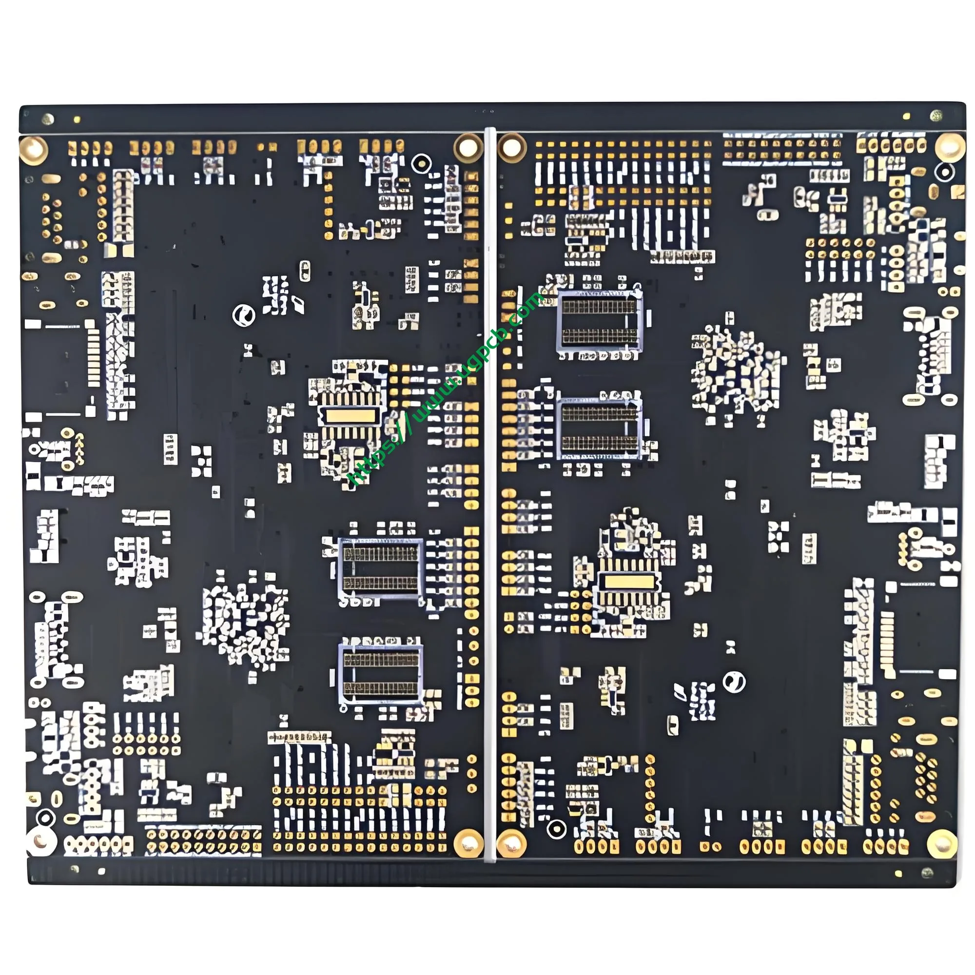
UGPCB presents this cooker hood motherboard PCB manufactured with Kingboard KB6165G high-end laminate. This double-sided rigid printed circuit board is specifically engineered for long‑term reliable operation in harsh kitchen environments. The PCB measures 82.63 × 46.7 mm with a standard 1.6 mm board thickness. Its double‑sided routing structure delivers excellent electrical performance and mechanical strength for medium‑complexity control circuits.
Industry data shows that China’s range hood control board shipments reached 38.60 million units in 2024, marking a 5.7% year‑over‑year growth. Smart control boards now account for 58.7% of total shipments. Given this substantial market demand, selecting a reliable and well‑manufactured cooker hood PCB directly impacts the end product’s quality and user experience.

2. Product Definition and Technical Specifications
2.1 Basic Parameters
| Parameter | Specification |
|---|---|
| Product Name | Cooker Hood Mother Board PCB |
| Laminate Material | Kingboard KB6165G (Halogen‑Free TG150 Glass Fiber Copper‑Clad Laminate) |
| Board Thickness | 1.6 mm |
| Number of Layers | 2 Layers (Double‑Sided Board) |
| Finished Size | 82.63 × 46.7 mm |
| Minimum Hole Diameter | 0.296 mm |
| Minimum Line Width / Line Spacing | 0.342 mm / 0.37 mm |
| Copper Foil Thickness | 1/1 OZ (35 μm per layer) |
| Surface Finish | Electroless Nickel / Immersion Gold (ENIG / Gold Plating Process) |
| Solder Mask / Legend | Black Solder Mask / White Silkscreen Legend |
2.2 Laminate Material: Kingboard KB6165G
This product uses KB6165G, a halogen‑free TG150 glass fiber copper‑clad laminate from Kingboard Laminates Holdings Ltd. This industrial‑grade high‑performance laminate delivers the following key properties:
- Glass Transition Temperature (Tg) : 150°C (155‑158°C measured by DSC method). The material withstands three lead‑free reflow soldering cycles with a peak temperature of 260°C.
- Comparative Tracking Index (CTI) : 600 V. This represents a threefold improvement over the base model KB‑6165F (CTI ≥ 175 V), offering exceptional resistance to tracking failure.
- Z‑axis Coefficient of Thermal Expansion (CTE) : Alpha 1 at 41 ppm/°C, Alpha 2 at 235 ppm/°C.
- T288 Delamination Time : > 60 minutes, several times higher than standard FR‑4 materials.
- Thermal Decomposition Temperature (Td, 5% weight loss) : 370°C.
- Flammability Rating : UL94 V‑0.
- Surface Resistivity : 5.2 × 10⁸ MΩ.
- Volume Resistivity : 6.1 × 10⁹ MΩ‑cm.
- Peel Strength : 1.4 N/mm (for 1 oz copper foil).
This laminate passes 96‑hour salt spray testing and is free of halogens, antimony, and red phosphorus, fully complying with RoHS environmental directives.
3. Design Principles and Operating Principles
3.1 Design Standard Compliance
This product’s design strictly follows IPC‑2221C, Generic Standard on Printed Board Design (released August 18, 2025). IPC‑2221C serves as the foundation design standard for all documents in the IPC‑2220 series. It establishes generic requirements for printed board design, covering material selection, copper foil selection, minimum electrical clearance, impedance tolerances, and other core design specifications.
3.2 Engineering Basis for Line Width and Spacing Design
This product features a design line width of 0.342 mm and line spacing of 0.37 mm. These parameters are determined based on the current‑carrying capacity formula from the IPC‑2221 standard:
I = k × ΔT^0.44 × A^0.725
Where:
- I = Maximum allowable current (Amperes, A)
- k = Correction factor (0.048 for outer layer traces, 0.024 for inner layer traces)
- ΔT = Temperature rise (°C)
- A = Conductor cross‑sectional area (mil²)
For this product with 1 oz copper foil (approximately 35 μm thickness), outer layer traces can carry approximately 1.5‑2 A per millimeter of width at a 10°C temperature rise. The 0.342 mm line width sufficiently meets the current‑carrying demands of range hood control circuits (typically including motor drive currents of 3‑5 A and touch/logic circuit currents below 1 A), while providing adequate process windows for subsequent PCBA soldering operations.
3.3 Operating Principles
The cooker hood motherboard PCB functions as the physical carrier of the control system, operating at three levels:
Electrical Connection Level : The copper traces on the PCB electrically connect the MCU (main control chip), touch sensing modules, motor driver ICs, LED driver circuits, and power management modules according to the schematic diagram, enabling orderly signal transmission.
Signal Processing Level : User commands entered through the touch panel (power on/off, airflow adjustment, lighting control, etc.) travel via touch traces on the PCB to the MCU. After processing, the MCU outputs corresponding control signals through the driver traces on the PCB to activate motors, LED lights, and other actuating components.
Power Management Level : Power traces on the PCB convert the input AC or DC power to the operating voltages required by each component. Proper power/ground plane layout ensures power supply stability.
4. Product Classification
Based on printed circuit board industry classification standards, this product falls into the following categories:
| Classification Dimension | Category |
|---|---|
| By Structure | Rigid Printed Circuit Board |
| By Layer Count | Double‑Sided Board (2‑Layer Board) |
| By Laminate Material | FR‑4.1 Grade Halogen‑Free Glass Fiber Copper‑Clad Laminate (KB6165G) |
| By Surface Finish | Electroless Nickel / Immersion Gold (ENIG) |
| By Application | Home Appliance Control Board (Cooker Hood Mother Board) |
| By Flammability Rating | UL94 V‑0 |
| By Environmental Compliance | Halogen‑Free, RoHS Compliant |
Per IPC‑6012F, Qualification and Performance Specification for Rigid Printed Boards (released September 2023), this product meets Class 2 – Dedicated Service Electronic Products requirements. Class 2 applies to products where extended life is expected and uninterrupted service is desired, but the operating environment is not extreme—perfectly matching home appliance applications.
5. Materials Used
5.1 Substrate: KB6165G Copper‑Clad Laminate
As detailed above, this product uses Kingboard KB6165G halogen‑free TG150 glass fiber copper‑clad laminate with the following material composition:
- Reinforcement : Electronic‑grade glass fabric
- Matrix Resin : Halogen‑free epoxy resin (Tg 150°C)
- Copper Foil : 1 oz Electrolytic Copper Foil (ED copper)
- Flame Retardant System : Halogen‑free flame retardant (UL94 V‑0)
5.2 Surface Finish: Electroless Nickel / Immersion Gold (ENIG)
This product uses the Electroless Nickel / Immersion Gold (ENIG) surface finish process. Per IPC‑4552B, Specification for Electroless Nickel/Immersion Gold (ENIG) Plating for Printed Boards (published May 2021), ENIG deposit thickness requirements are:
- Nickel Layer Thickness : 3‑6 μm (per IPC‑4552B Class 1/2/3)
- Gold Layer Thickness : 0.05‑0.10 μm (typical range: 0.075‑0.125 μm)
ENIG surface finish offers these advantages:
- Excellent solderability, meeting the highest coating durability rating per IPC‑J‑STD‑003
- Superior oxidation and corrosion resistance
- Flat surface suitable for fine‑pitch component soldering
- Suitable for wire bonding and contact finish applications
5.3 Solder Mask and Legend
- Solder Mask : Black ink offering excellent insulation and heat resistance
- Legend : White silkscreen providing high contrast for SMT placement and repair identification
6. Product Structure and Performance Characteristics
6.1 Structural Features
Double‑Sided Design (2 Layers) : Both the Top Layer and Bottom Layer contain circuit traces, with electrical connections between layers made through Plated Through‑Holes (PTH). The double‑sided structure balances routing density with cost‑effectiveness.
Precision Hole Diameter Control : Minimum hole diameter of 0.296 mm meets the strict requirements of IPC‑6012F for plated through‑holes. Copper plating on hole walls ensures reliable interlayer connections and conductivity.
Compact Dimensions : The 82.63 × 46.7 mm compact size is specifically tailored for the limited internal space of range hoods, facilitating overall product mechanical design.
Standard 1.6 mm Board Thickness : This thickness maintains mechanical strength while matching standard component lead lengths, facilitating PCBA assembly.
6.2 Performance Characteristics
Superior Heat Resistance : With Tg of 150°C and Td of 370°C, the board withstands the high‑temperature impact of lead‑free reflow soldering (peak 260°C).
Excellent Insulation Performance : Surface resistivity of 5.2 × 10⁸ MΩ and volume resistivity of 6.1 × 10⁹ MΩ‑cm ensure reliable signal transmission in high‑humidity kitchen environments.
High CTI Tracking Resistance : The CTI 600 V rating effectively prevents tracking failure in high‑pollution environments (kitchen fume environments fall under Pollution Degree 2‑3).
Good Anti‑CAF Performance : The laminate offers strong resistance to Conductive Anodic Filament (CAF) formation, reducing the risk of CAF failure in moist‑heat environments.
UL94 V‑0 Flammability Rating : Meets the highest fire safety requirements for home appliances.
7. Manufacturing Process Flow
UGPCB manufactures this cooker hood motherboard PCB in strict compliance with IPC‑6012F requirements:
Step 1: Incoming Quality Control (IQC) → Inspect KB6165G copper‑clad laminate, copper foil, dry film, solder mask ink, and other raw materials
Step 2: Cutting → Cut large copper‑clad laminate sheets to working panel size
Step 3: Drilling → CNC drilling machines process the 0.296 mm minimum hole diameter along with other mounting holes and vias
Step 4: Electroless Copper Deposition / Panel Plating → Metallize hole walls to create conductive through‑holes
Step 5: Pattern Transfer → Apply dry film → Expose → Develop to form the circuit pattern
Step 6: Etching → Remove unprotected copper to create the designed circuit traces
Step 7: Solder Mask → Print black solder mask ink → Expose → Develop to expose pads
Step 8: ENIG (Electroless Nickel / Immersion Gold) → Electroless nickel plating (3‑6 μm) + Immersion gold (0.05‑0.10 μm)
Step 9: Legend Printing → Print white silkscreen legend identifiers
Step 10: Routing / V‑Cut → CNC routing to final dimensions of 82.63 × 46.7 mm
Step 11: Electrical Testing → Flying probe testing / fixture testing to verify open/short circuit integrity
Step 12: Final Quality Control (FQC) → Visual inspection and dimensional inspection per IPC‑6012F Class 2 standards
Step 13: Packaging and Shipping → Vacuum packaging + anti‑static bags, compliant with IPC packaging specifications
8. Application Scenarios and Market Applications
8.1 Primary Application Scenarios
This cooker hood motherboard PCB is widely used in:
- Residential Range Hoods : Main control circuit boards for touch‑control or button‑type range hoods
- Integrated Cooktop Control Boards : Core control units for integrated cooking appliances
- Smart Kitchen Appliances : Control modules for smart range hood and cooktop integrated systems
- Commercial Kitchen Equipment : Control boards for large commercial exhaust systems

8.2 Market Outlook
China’s small appliance control board market is projected to reach approximately RMB 45 billion in 2025, with year‑over‑year growth of 10.3%. Smart control boards now account for over 60% of the market. The Chinese home appliance control board market is in a critical stage of smart transformation and upgrade, driving sustained demand for high‑performance, high‑reliability cooker hood motherboard PCBs.
8.3 Typical Operating Environment
The cooker hood motherboard PCB operates under these conditions:
- Temperature Range : ‑10°C to +85°C (kitchen environment)
- Humidity Range : 20% to 90% RH (significant steam generated during cooking)
- Pollution Degree : Pollution Degree 2‑3 (fume and dust)
- Vibration : Continuous vibration from motor operation
9. Why Choose UGPCB for Your Cooker Hood Mother Board PCB?
✅ International Standard Compliance : Full adherence to IPC‑2221C and IPC‑6012F international standards throughout design, manufacturing, and inspection
✅ Premium Laminate Materials : Kingboard KB6165G industrial‑grade laminate with Tg 150°C, CTI 600 V, and UL94 V‑0 rating
✅ Precision Manufacturing Capability : Minimum hole diameter of 0.296 mm and minimum line width of 0.342 mm
✅ Superior Surface Finish : ENIG finish compliant with IPC‑4552B, offering excellent solderability
✅ Environmental Compliance : Halogen‑free materials meeting RoHS and REACH directives
✅ Customization Services : Flexible customization of dimensions, layer count, laminate material, and surface finish
✅ Rapid Delivery : Quick‑turn capability from prototypes to volume production
Request a Quote
Get Your Free Quote Today
UGPCB is committed to providing high‑quality cooker hood motherboard PCB manufacturing services to customers worldwide. Whether you need prototype samples or volume production, we offer professional technical support and competitive pricing.
📞 Contact us for a free PCB prototype quote
📧 Email: sales@ugpcb.com
🌐 Website: www.ugpcb.com
💡 Please provide the following information for an accurate quote:
- PCB dimensions, layer count, and laminate material requirements
- Minimum line width/spacing and minimum hole diameter
- Surface finish requirements
- Copper foil thickness requirements
- Quantity requirements (prototype / small batch / volume production)
- Gerber files (if available)
Send your requirements today, and the UGPCB professional team will respond with a detailed quote and technical recommendations within 24 hours!
Data Source Declaration
The technical data and standards cited in this article are sourced from the following authoritative organizations and publicly available materials:
- IPC‑6012F : Qualification and Performance Specification for Rigid Printed Boards, September 2023, IPC International, Inc.
- IPC‑2221C : Generic Standard on Printed Board Design, August 18, 2025, IPC International, Inc.
- IPC‑4552B : Specification for Electroless Nickel/Immersion Gold (ENIG) Plating for Printed Boards, May 2021, IPC International, Inc.
- KB‑6165G / KB‑6165GMD Technical Data Sheet : Kingboard Laminates Holdings Ltd. official product technical documentation
- UL94 : Standard for Tests for Flammability of Plastic Materials for Parts in Devices and Appliances, Underwriters Laboratories Inc.
- IPC‑TM‑650 : Test Methods Manual, IPC International, Inc.













