

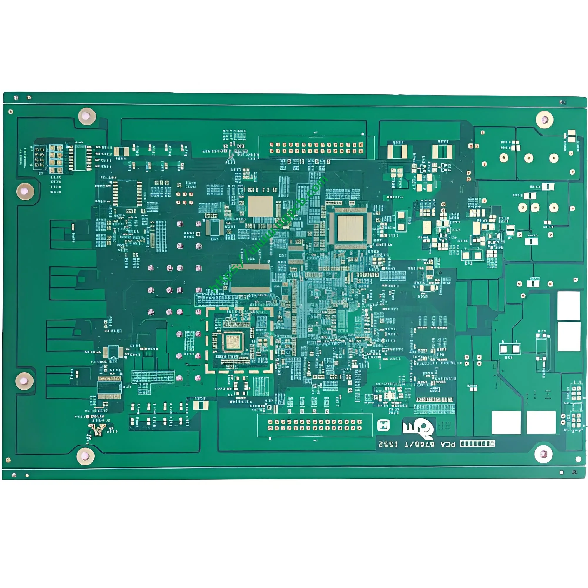
I. Product Overview: What Is an Electric Guitar Speaker PCB?
An electric guitar speaker PCB is a specialized printed circuit board designed for electric guitar amplifiers. It serves as the central backbone for signal processing and power amplification in guitar amplification systems. This board carries critical circuits including preamplifiers, power amplifiers, and tone control networks, all of which directly influence the sound quality, dynamic range, and tonal character of the electric guitar output.
UGPCB presents this electric guitar amplifier PCB as a double-sided FR-4 rigid printed board manufactured to rigorous industry standards. The board is optimized for Class D amplifier applications and other audio use cases in electric guitar amplification systems.
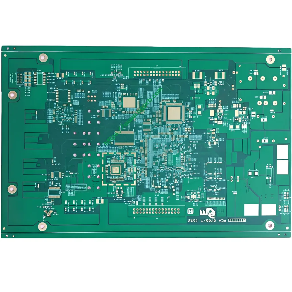
II. Product Specifications
| Parameter | Specification |
|---|---|
| Product Name | Electric Guitar Speaker PCB |
| Substrate Material | FR-4 Glass Fiber Epoxy Copper-Clad Laminate |
| Board Thickness | 1.0 mm |
| Layer Count | 2 Layers (2L) |
| Dimensions | 86.9 × 73.58 mm |
| Minimum Hole Diameter | 0.236 mm |
| Line Width / Line Spacing | 0.32 mm / 0.37 mm |
| Copper Foil Thickness | 1/1 OZ (1 oz on both outer layers) |
| Surface Finish | Lead-Free Hot Air Solder Leveling (LF HASL) |
| Solder Mask / Legend | Green Solder Mask / White Silkscreen Legend |
III. Scientific Classification Under IPC Standards
Per IPC-6012F, Qualification and Performance Specification for Rigid Printed Boards, this product falls into the following scientific classification:
- Construction Type: Type 2 (Double-Sided Board) — double-sided routing with plated-through holes (PTH)
- Performance Class: Class 2 (Dedicated Service Electronic Products) — suitable for continuous operation applications requiring high reliability, such as audio equipment
- Substrate Material: FR-4 (Glass-Reinforced Epoxy) — compliant with IPC-4101 requirements
- Surface Finish: Lead-Free HASL (LF HASL) — RoHS-compliant
IV. Design Considerations and Engineering Principles
4.1 Substrate Selection: The Engineering Basis for FR-4
FR-4 is the industry designation for glass-reinforced epoxy resin copper-clad laminate. It represents the most widely used PCB substrate material globally. Per IPC-4101, Specification for Base Materials for Rigid and Multilayer Printed Boards, FR-4 materials are classified by glass transition temperature (Tg) into multiple tiers:
- Standard FR-4: Tg of 130–140°C
- Mid-Tg FR-4: Tg of 150–160°C
- High-Tg FR-4: Tg ≥ 170°C
This electric guitar speaker PCB uses standard FR-4 laminate with a Tg of 130–140°C. The long-term operating temperature typically does not exceed 105°C, which fully meets the thermal reliability requirements for low-to-medium power electric guitar amplifier applications.
4.2 Design Rationale for 1.0 mm Board Thickness
The 1.0 mm thickness represents one of the most common specifications for double-sided FR-4 PCBs. This thickness achieves an optimal balance among mechanical strength, electrical performance, and manufacturing cost:
- Provides adequate mechanical support against component insertion and vibration stress
- Maintains appropriate dielectric thickness for controlled impedance
- Facilitates compatibility with standard connectors and enclosure designs
4.3 Current-Carrying Capacity Analysis for 0.32/0.37 mm Line Width/Spacing
Per IPC-2221C, Generic Standard on Printed Board Design, the current-carrying capacity of PCB conductors can be calculated using the following formula:
Where:
- I = Maximum current-carrying capacity (A)
- ΔT = Allowable temperature rise (°C)
- A = Conductor cross-sectional area (mil²), where A = W × T
- k = Empirical constant (k = 0.048 for outer layers, k = 0.024 for inner layers)
For outer layer traces with 1 oz copper thickness (1 oz = 1.378 mil) and 0.32 mm line width (≈12.6 mil):
- Cross-sectional area A = 12.6 × 1.378 ≈ 17.4 mil²
- Under 10°C temperature rise conditions, the theoretical current-carrying capacity per trace is approximately 1.8–2.2 A
This current capacity fully satisfies the requirements of electric guitar amplifier preamplifier and signal processing circuits.
4.4 Engineering Significance of 0.236 mm Minimum Hole Diameter
The 0.236 mm (approximately 9.3 mil) minimum hole diameter falls within the standard drilling precision range for the PCB industry. This hole size supports the through-hole mounting of the vast majority of standard leaded components, including resistors, capacitors, transistors, and ICs. It also ensures reliable metallization of plated-through holes (PTH) with sufficient wall area for dependable solder joints.
4.5 Copper Foil Thickness: 1/1 OZ
One ounce (1 OZ) of copper foil corresponds to a thickness of approximately 35 μm. The 1/1 OZ specification—1 oz on both outer layers—ensures:
- Consistent current-carrying capacity across both outer layers
- Excellent signal integrity
- Sufficient solder joint strength and long-term reliability
4.6 Lead-Free HASL Surface Finish
Lead-Free Hot Air Solder Leveling (LF HASL) involves immersing the PCB into molten lead-free solder—typically SAC305 alloy (Tin 96.5%, Silver 3.0%, Copper 0.5%)—followed by high-pressure hot air knives that level the surface to create a uniform, solderable protective coating.
Process Parameters:
- Solder Pot Temperature: 250–265°C
- Immersion Time: 1–5 seconds
- Solder Coating Thickness: 1–40 μm
Key Advantages of Lead-Free HASL:
- ✅ RoHS Compliance: Lead content below the 0.1% (1000 ppm) threshold
- ✅ Cost-Effectiveness: One of the most economical surface finish options available
- ✅ Excellent Solderability: Superior wettability and solder joint reliability
- ✅ Extended Shelf Life: Up to 12 months or more
Typical Applications: Consumer electronics, audio equipment, industrial controls, and other applications where surface flatness requirements are not extremely stringent.
V. Working Principle: From Guitar Signal to Speaker Sound
The electric guitar speaker PCB operates through three core stages of signal processing:
5.1 Preamplifier Section
The preamplifier represents the heart of the guitar amplifier circuit board. It processes the weak electromagnetic signals from the guitar pickups and controls multiple aspects of the sound:
- Current Gain
- Power Gain
- Tone Shaping (Treble, Midrange, Bass)
5.2 Power Amplifier Section
After preamplifier processing, the signal passes to the power amplifier stage. The power amplifier further amplifies the signal to a level sufficient to drive the speaker, while maintaining compatibility with higher operating voltages.
5.3 Speaker Output
The amplified signal ultimately drives the speaker, converting electrical energy into audible sound waves.
VI. Common Components on Guitar Amplifier PCBs
Electric guitar speaker PCBs integrate a wide range of components that collectively perform signal processing and power amplification functions:
| Component Category | Function |
|---|---|
| Diodes and Resistors | Rectification, current limiting, voltage division, biasing |
| Inductors and Capacitors | Filtering, decoupling, frequency response control |
| Low-Pass Filters and Decoupling Capacitors | High-frequency noise suppression, power supply stabilization |
| Transistors and Transformers | Signal amplification, impedance matching, voltage conversion |
These components enable the electric guitar speaker PCB to support both Solid-State and Tube amplifier technologies.
VII. Manufacturing Process Flow
UGPCB manufactures this electric guitar speaker PCB in strict accordance with IPC-6012F requirements:
- Incoming Quality Control (IQC) : FR-4 substrate, copper foil, solder mask ink, and other raw materials inspection
- Inner Layer Circuitry (not applicable for double-sided boards; proceed to next step)
- Drilling: Minimum hole diameter 0.236 mm using high-precision CNC drilling
- Electroless Copper Deposition / Electroplating: Plated-through hole (PTH) metallization, copper build-up
- Outer Layer Circuitry: Dry film lamination → Exposure → Development → Etching → Film stripping
- Solder Mask Application: Green solder mask ink covering non-solderable areas
- Legend Printing: White silkscreen legend indicating component reference designators
- Surface Finish: Lead-Free HASL (LF HASL)
- Profile Routing: CNC routing to final dimensions of 86.9 × 73.58 mm
- Electrical Testing: Flying probe testing / fixture testing to verify electrical continuity
- Final Inspection: Visual inspection per IPC-A-600K requirements
- Packaging and Shipping: Vacuum packaging with moisture protection
VIII. Application Scenarios and Use Cases
8.1 Primary Applications
- Electric Guitar Amplifiers: Class D amplifiers, Class AB amplifiers
- Bass Guitar Amplifiers: Low-frequency power amplification
- Guitar Effects Pedals: Signal processing and tone modulation
- Professional Audio Equipment: Studio monitors, PA systems
8.2 Special Adaptation for Class D Amplifiers
Class D amplifiers are renowned for their high efficiency (exceeding 90%) and high power output. This electric guitar speaker PCB is particularly well-suited for Class D bass guitar amplifier designs, offering:
- Average power output of approximately 100 W
- Excellent volume control capability
- Deep, rich bass response
- Faster transient response
IX. Quality and Reliability Assurance
9.1 IPC Standards Compliance
The manufacturing and inspection of this electric guitar speaker PCB strictly adhere to the following IPC standards:
| Standard | Title | Application |
|---|---|---|
| IPC-6012F | Qualification and Performance Specification for Rigid Printed Boards | Full-process manufacturing and acceptance |
| IPC-A-600K | Acceptability of Printed Boards | Visual inspection and quality determination |
| IPC-4101 | Specification for Base Materials for Rigid and Multilayer Printed Boards | Substrate selection and certification |
| IPC-2221C | Generic Standard on Printed Board Design | Design specifications and current-carrying calculations |
9.2 Reliability Metrics
- Shelf Life: ≥ 12 months (with lead-free HASL surface finish)
- Operating Temperature Range: 0–105°C (standard FR-4)
- Flammability Rating: UL94 V-0 (standard for FR-4 substrate material)
X. Why Choose UGPCB?
UGPCB is a globally recognized PCB design, manufacturing, and turnkey PCBA service provider:
- 🏭 Modern Facility: 28,000 m² production facility
- 👨🔧 Expert Team: 1,300 employees, 35% technical experts
- 🌍 Global Reach: Serving over 5,000 enterprise customers across 20+ countries
- 📦 Volume Delivery: Over 100,000 PCBA batches delivered cumulatively
- 🔧 Turnkey Services: From PCB design optimization and component sourcing to SMT/DIP assembly and functional testing
XI. Inquiries and Ordering
📞 Contact us today for a custom quote and technical support!
- 🌐 Website: www.ugpcb.com
- 📧 Email: sales@ugpcb.com
- 📱 Phone: +86-135 4412 8719
- 💬 WhatsApp:+86 19072115165
Simply upload your Gerber files, BOM list, and design files. The UGPCB team will provide a complete quotation within 24 hours.
Data Source Statement
The technical data and standard information cited in this article are derived from the following authoritative sources:
- IPC (Association Connecting Electronics Industries) — IPC-6012F, IPC-A-600K, IPC-4101, IPC-2221C series standards
- IPC-6012F: Qualification and Performance Specification for Rigid Printed Boards (October 2023 release)
- IPC-A-600K: Acceptability of Printed Boards (July 2020 release)
- IPC-2221C: Generic Standard on Printed Board Design (2023 release)
- IPC-4101: Specification for Base Materials for Rigid and Multilayer Printed Boards
- UL94: Standard for Safety of Flammability of Plastic Materials for Parts in Devices and Appliances
All data in this article is sourced from official IPC standard documents and industry authoritative references, ensuring the accuracy and reliability of all technical parameters.













