
As digital electronics evolve toward higher integration, lighter weight, and uncompromised reliability, Rigid-Flex PCBs have become the critical backbone for complex circuit systems. When space constraints and signal integrity are paramount, combining epoxy resin plugging with rigid-flex technology represents the gold standard for high-density interconnect solutions.
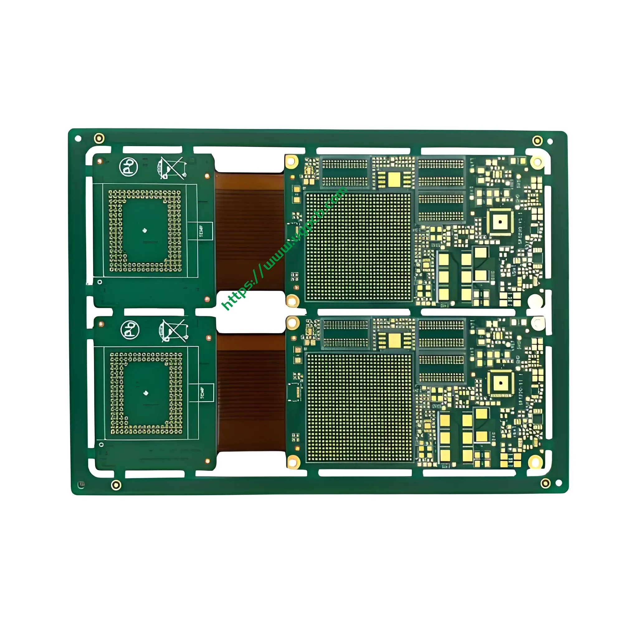
UGPCB leverages advanced manufacturing to deliver an Epoxy Resin Plugged Rigid-Flex PCB built on a FR4 + PI material platform. Featuring a 16L Rigid + 2L Flex construction, this board is specifically engineered for demanding digital products, offering the mechanical strength of rigid boards alongside the dynamic flexing capability of flexible circuits.

1. Product Overview & Definition
An epoxy resin plugged rigid-flex PCB is a hybrid circuit board that integrates rigid PCB sections and flexible PCB sections into a single, unified structure through lamination. This specific product combines 16 rigid layers (FR4) with 2 flexible layers (PI). The rigid section’s vias are filled using a specialized epoxy resin plugging process.
This design retains the bendability of the flex area while eliminating common rigid-flex failure points like “solder blow-out” or trapped air expansion during SMT assembly. The result is a highly reliable circuit board optimized for modern, compact digital devices.
2. Materials & Stack-Up Architecture
The product’s performance relies on precise material selection and structural engineering:
-
Base Materials:
-
Rigid Section: FR4 (Glass-reinforced epoxy laminate). This material offers high mechanical strength, excellent thermal stability, and electrical insulation (meets UL 94 V-0 flammability rating), providing a stable foundation for component mounting.
-
Flex Section: PI (Polyimide) film. Known for its exceptional heat resistance (operating range: -200°C to +300°C), outstanding dynamic flex life (millions of cycles), and low dielectric constant, PI is ideal for dynamic flexing applications.
-
-
Stack-Up Configuration:
-
Total Layers: 16L Rigid + 2L Flex (Equivalent to an 18-layer circuit)
-
Copper Thickness: 1 OZ. As per IPC-4562, 1 OZ copper finished thickness is approximately 35µm. This provides an optimal balance between current-carrying capacity and fine-line etching capability.
-
Finished Board Thickness: 1.0mm. Achieving this thickness in an 18-layer stack demonstrates advanced lamination precision, meeting the industry’s demand for ultra-slim profiles.
-
Surface Finish: Immersion Gold (ENIG). Conforming to IPC-4552, ENIG offers a flat surface, excellent solderability, and superior oxidation resistance, making it ideal for fine-pitch component assembly.
-
3. Epoxy Resin Plugging: Working Principle & Design Considerations
3.1 Working Principle
In a multilayer rigid-flex PCB, vias electrically connect different layers. In traditional designs, unplugged vias can trap air. During high-temperature processes like lead-free reflow (peak temperatures around 245°C–260°C), this trapped air expands, potentially causing “popcorning,” delamination, or solder ball splatter.
The epoxy resin plugging process uses vacuum printing or injection to fill mechanical drilled holes (minimum size 0.2mm) with a high-viscosity, low-CTE (Coefficient of Thermal Expansion) epoxy resin. After filling, the board undergoes thermal curing and surface planarization, making the via surface flush with the board surface.
3.2 Design Considerations
-
Aspect Ratio Control: For a 0.2mm minimum finished hole size, the aspect ratio (board thickness to hole diameter) must be controlled to ensure void-free filling. With a 1.0mm board thickness, the aspect ratio is 5:1, well within UGPCB’s stringent process capabilities.
-
Trace/Space Capability: This product supports 4mil/4mil (0.1mm/0.1mm) fine-line circuitry. According to IPC-2221, such precision allows for high-density interconnects. The plugging process is carefully managed to not compromise the insulation distance between these fine traces.
4. Product Classification
Based on IPC-6013, the qualification and performance specification for flexible and rigid-flex boards, this product’s scientific classification is:
-
Structural Type: Type 4 (Rigid-Flex Multilayer Board)
-
Performance Class: Class 3 (High-Reliability Electronic Products). This class is for products where continued performance is critical, such as medical devices, industrial controls, and high-end digital consumer goods. It demands a high level of assurance and proven reliability.
5. Manufacturing Process & Quality Control
UGPCB follows IPC-A-600 standards for manufacturing and acceptance. The core process includes:
-
Inner Layer Imaging: Fine-line circuitry is patterned on both PI and FR4 substrates, with strict control over the 4mil trace/space geometry.
-
Coverlay Lamination: PI coverlay is applied to the flex areas to protect circuits and enhance flex life.
-
Window Cutting & Lay-up: Rigid sections are windowed to expose flex areas, followed by precise alignment and lay-up.
-
Lamination: High temperature and pressure fuse the multilayer stack. This step is critical to avoid wrinkles or separation at the rigid-flex interface.
-
Mechanical Drilling: 0.2mm micro vias are drilled with positional accuracy held within ±0.05mm.
-
Epoxy Resin Plugging: Core Process. Vacuum plugging equipment injects epoxy resin. After curing and sequential grinding, surface planarity meets IPC-4761 Type VII (Filled & Covered) standards, providing sealed via protection.
-
ENIG Surface Finish: Applied per IPC-4552, ensuring a dense, uniform gold layer free from “black pad” defects.
-
Electrical Testing: 100% flying probe or fixture testing verifies no opens or shorts.
6. Key Specifications & Reliability Data
All parameters are grounded in industry standards to ensure accuracy and authority:
| Parameter | Specification | Standard / Reference |
|---|---|---|
| Layer Count | 16L Rigid + 2L Flex | Rigid-Flex Hybrid |
| Base Material | FR4 + PI | UL 94 V-0 Certified |
| Finished Thickness | 1.0mm ±10% | IPC-4562 |
| Minimum Hole Size | 0.2mm | Mechanical Drilling Capability |
| Min Trace/Space | 4mil / 4mil (0.1mm/0.1mm) | IPC-2221 (Fine-Line) |
| Copper Thickness | 1 OZ (35µm) | Finished Copper; Meets Current Needs |
| Surface Finish | Immersion Gold (ENIG) | IPC-4552; Shelf Life ≥12 Months |
| Thermal Stress Test | 288°C, 10 seconds, 3 cycles | IPC-TM-650 2.4.13; No delamination |
| Insulation Resistance | ≥ 10^12 Ω (Normal State) | High Insulation Requirement |
| Flex Life | > 100,000 cycles (Dynamic) | Based on PI Material Properties |
*Data references: IPC-TM-650 test method manual and UL certification standards.*
7. Applications
Thanks to the high-density routing of the 16L rigid section and the dynamic flex capability of the 2L flex section, this product is primarily targeted at high-end digital products:
-
High-End Smartphones & Tablets: Used for camera modules, battery connections, and mainboard interconnects to save internal space.
-
Digital Cameras & Camcorders: Ideal for lens extension modules requiring repeated, high-frequency bending.
-
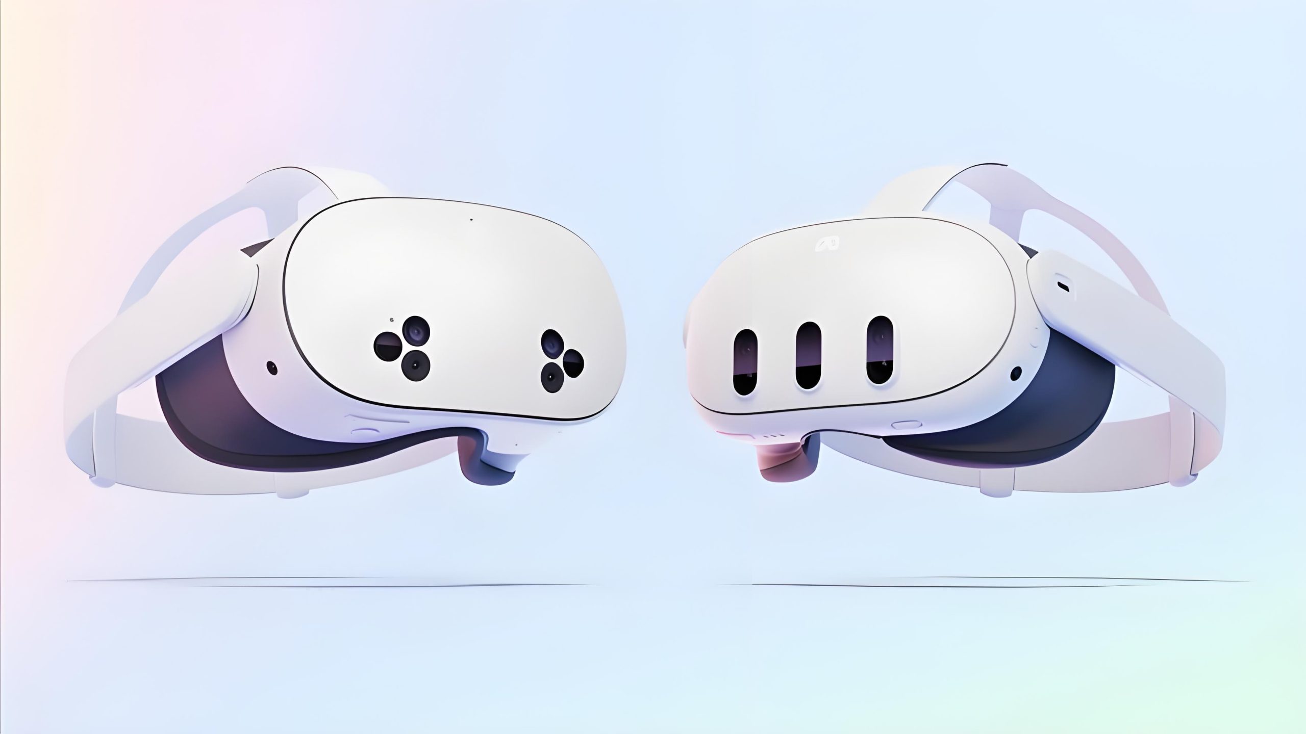
Wearable Electronics: Smartwatches, VR/AR headsets. The 1.0mm thin profile and epoxy plugging ensure signal stability in ultra-compact enclosures.
-
Solid-State Drives (SSDs): Used as the carrier for memory modules, leveraging rigid-flex for multi-layer stacking and interface connections.
8. Product Features & Advantages
-
Integrated Design, Saves Space: Replaces the traditional “PCB + Connector + FPC” assembly. This eliminates connectors, reduces BOM costs, and significantly improves signal integrity by minimizing impedance discontinuities.
-
Epoxy Resin Plugging Eliminates Solder Blow-Out: Solves the yield-loss issue caused by outgassing from vias during lead-free reflow soldering.
-
Fine-Line Circuitry: Supports 4mil/4mil trace and space, enabling high-density interconnect (HDI) designs. The 0.2mm micro vias offer high routing freedom.
-
High Thermal Stability & Flex Durability: The FR4 and PI combination provides a robust platform for component assembly while ensuring long-term dynamic flex performance.
9. Call to Action & Inquiry Guidance
UGPCB is more than a circuit board manufacturer. We are your partner in ensuring product reliability.
We understand the manufacturing challenges of epoxy resin plugged rigid-flex PCBs. The key is controlling adhesion at the rigid-flex boundary and guaranteeing void-free plugging. With years of experience, UGPCB utilizes automated vacuum plugging lines, high-precision direct imaging, and rigorous AOI systems. Every 16L Rigid + 2L Flex board we ship meets Class 3 reliability standards.
If you need a rigid-flex PCB that can handle high-density routing, lead-free assembly, and dynamic flexing without compromise, UGPCB is your ideal partner.
Contact UGPCB today for a custom quote.
-
Submit your Gerber files. Our team will provide a free DFM (Design for Manufacturing) analysis within 24 hours.
-
We support prototype and low-to-medium volume production with flexible lead times.
-
Our dedicated engineering team offers one-on-one support to accelerate your digital product launch.


