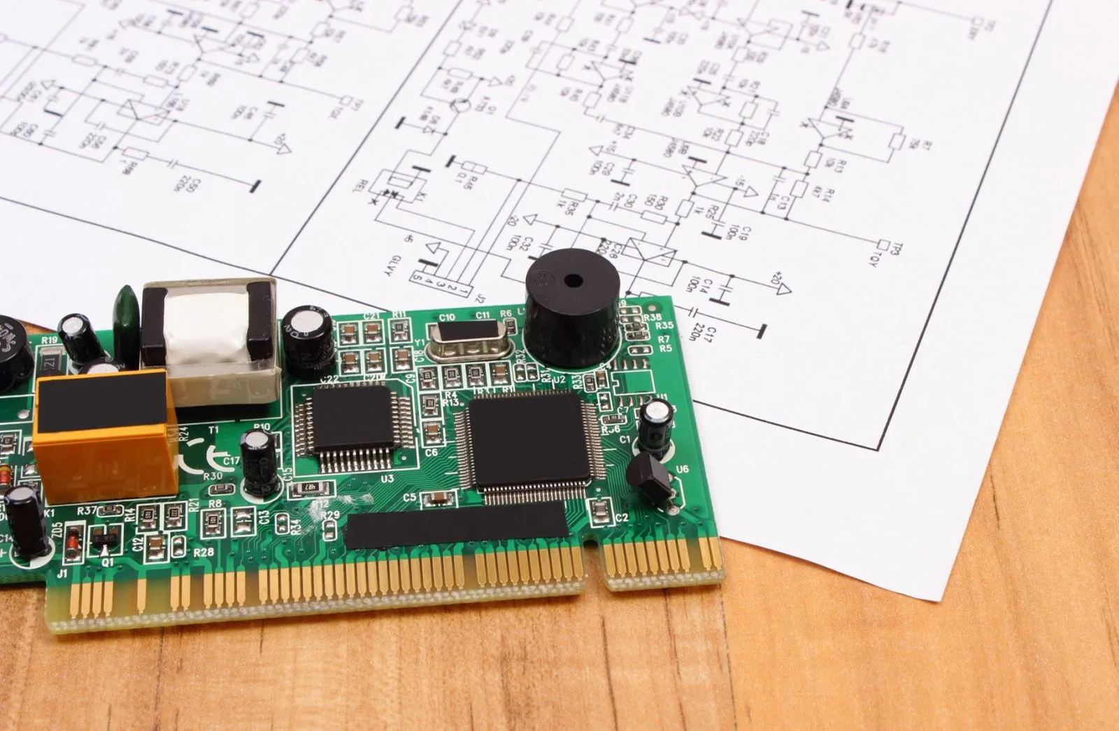
การออกแบบ PCB RF
โซลูชั่นการออกแบบ RF PCB: แพลตฟอร์มมืออาชีพที่ให้อำนาจแอพพลิเคชั่นความถี่สูง
ความท้าทายหลักและคุณค่าของการออกแบบวงจรความถี่สูง
ในสาขาต่าง ๆ เช่นการสื่อสารไร้สาย, ระบบเรดาร์, การนำทางดาวเทียม, และอุปกรณ์ 5G/6G, การออกแบบ RF PCB เป็นเทคโนโลยีหลักที่กำหนดความสมบูรณ์ของสัญญาณ, ประสิทธิภาพการส่งพลังงาน, และความน่าเชื่อถือของระบบ. ความท้าทายหลัก ได้แก่:
- การควบคุมการสูญเสียสัญญาณความถี่สูง: ผลกระทบต่อผิวหนัง, การสูญเสียอิเล็กทริก, และความต้านทานต่อความไม่ตรงกันก็มีความสำคัญที่ความถี่ GHz.
- ความเข้ากันได้ของแม่เหล็กไฟฟ้า (EMC) การเพิ่มประสิทธิภาพ: การลด crosstalk และรังสีเพื่อให้เป็นไปตามมาตรฐานการรับรองที่เข้มงวดเช่น FCC และ CE.
- 3D สนามแม่เหล็กไฟฟ้าร่วมกัน: การเพิ่มประสิทธิภาพการกระจายการกระจายฟิลด์สำหรับโครงสร้างสายส่งเช่น microstrips และท่อนำคลื่น coplanar.
- การมีเพศสัมพันธ์หลายทางเทคนิคเชิงความร้อน: ปรับสมดุลการกระจายความร้อนและความเสถียรเชิงกลในสถานการณ์พลังงานสูง.
เป็นความสามารถหลัก, UGPCB มุ่งมั่นที่จะช่วยเหลือลูกค้าให้บรรลุตัวบ่งชี้ประสิทธิภาพหลัก เช่น การสูญเสียการแทรก ≤0.3dB/นิ้ว (@28GHz), VSWR <1.5, และความสม่ำเสมอของเฟส ±2° ผ่านการตรวจสอบการจำลองแบบเต็มกระบวนการและนวัตกรรมกระบวนการ.
ตารางแสดงความสามารถทางวิชาชีพของเรา: ตั้งแต่การเลือกวัสดุ PCB ไปจนถึงการผลิต
การเลือกวัสดุความถี่สูงและการกำหนดลักษณะเฉพาะ
- ห้องสมุดวัสดุอิเล็กทริก: ครอบคลุมลามิเนตความถี่สูง เช่น ซีรีส์ Rogers RO4000®, ทาโคนิค ทีแอลวาย, และ Isola I-Tera® MT, ที่มีค่าคงที่ไดอิเล็กทริก (ดีเค) ตั้งแต่ 2.2 ถึง 10.2 และการสูญเสียแทนเจนต์ (ฟ) ต่ำสุด 0.0015.
- การบำบัดด้วยฟอยล์ทองแดง: ผสมผสานทองแดงโปรไฟล์ต่ำพิเศษ (กองทัพอากาศ/VLP) ด้วยการบำบัดออกไซด์สีน้ำตาลเพื่อให้ได้ความหยาบผิว Ra <0.3μm.
- การออกแบบกองซ้อนอิเล็กทริกแบบไฮบริด: รองรับการเคลือบไฮบริด PTFE และ FR-4 เพื่อความสมดุลด้านต้นทุนด้านประสิทธิภาพที่เหมาะสมที่สุด.
การออกแบบการควบคุมความต้านทานที่แม่นยำ
- ใช้การจำลองแบบเต็มคลื่นSONNET®/HFSS สำหรับการออกแบบระบบแบบหลายแรงกระตุ้น (50o/75o/100Ω).
- ควบคุมความทนทานต่อความยาวคู่ที่แตกต่างกันภายใน± 5mil และความทนทานต่อความต้านทานต่อความต้านทานภายใน± 5%.
- คุณสมบัติอัลกอริธึมการชดเชยขอบที่เป็นกรรมสิทธิ์เพื่อกำจัดการบิดเบือนสนามไมโครสตริปขอบ.
3D สถาปัตยกรรมการป้องกันแม่เหล็กไฟฟ้า
- ใช้งานผ่านเทคโนโลยีการป้องกันรั้วพร้อมการแยก >60db @10GHz.
- ออกแบบโครงสร้างท่อนำคลื่นที่ฝังอยู่เพื่อยับยั้งการแพร่กระจายของคลื่นพื้นผิว.
- เพิ่มประสิทธิภาพการรบกวนของพื้นดิน RF ผ่านการแบ่งส่วนระนาบพื้นดินที่มีการแปล.
การเชื่อมต่อระหว่างกันที่มีความหนาแน่นสูง (HDI) การรวมเข้าด้วยกัน
- บรรลุความแม่นยำในการขุดเจาะเลเซอร์ที่±25μmสำหรับ vias คนตาบอดและฝังศพ, รองรับการออกแบบ microvia 0.1 มม..
- ใช้เทคโนโลยี HDI ทุกชั้นสำหรับการบูรณาการ 20+ อาร์เรย์เสาอากาศคลื่นมิลลิเมตร.
- ควบคุมความหนาของการชุบนิ้วทองที่ 0.05–0.2μm, สร้างความมั่นใจในการต้านทานการสัมผัส <10MΩ.
ระบบสนับสนุนด้านเทคนิคแบบครบวงจรของเรา
เพื่อตรวจสอบความสมเหตุสมผลของการออกแบบ, เรายังต้องทำการตรวจสอบเหตุผลระหว่างการออกแบบ PCB ด้วย, การผลิต, และขั้นตอนการทดสอบ. สิ่งนี้ช่วยให้เราสามารถระบุปัญหาใด ๆ ได้ทันที, ตรวจสอบให้แน่ใจว่าผลิตภัณฑ์ของคุณได้รับการผลิตอย่างปลอดภัยและผ่านการควบคุมคุณภาพ.
ขั้นตอนการตรวจสอบการออกแบบ
- การจำลองทางแม่เหล็กไฟฟ้า: แยกพารามิเตอร์ S ในย่านความถี่เต็มโดยใช้ ANSYS HFSS/CST.
- การจำลองความร้อน: วิเคราะห์การกระจายความร้อนของอุปกรณ์ไฟฟ้าด้วย Flotherm®.
- การตรวจสอบความน่าเชื่อถือ: ดำเนินการทดสอบ HALT (-55℃ถึง 150 ℃ปั่นจักรยาน, 20จี การสั่นสะเทือน).
การควบคุมกระบวนการผลิต
- ใช้การถ่ายภาพด้วยเลเซอร์โดยตรง (LDI) เทคโนโลยีที่มีความทนทานต่อความกว้างของเส้น ±8%.
- ใช้กระบวนการพลาสมาเดสเมียร์เพื่อให้แน่ใจว่าผนังรูความถี่สูงมีความหยาบ <1μm.
- ใช้การเคลือบสูญญากาศเพื่อรักษาความเบี่ยงเบนของความหนาไดอิเล็กทริกระหว่างชั้น <3%.
การทดสอบและการรับรอง
- ดำเนินการวิเคราะห์เครือข่ายเวกเตอร์ (VNA) การทดสอบด้วยความครอบคลุมความถี่จาก DC ถึง 110GHz.
- ค้นหาแหล่งกำเนิดรังสี EMI โดยใช้ระบบสแกนใกล้สนาม.
- ดำเนินการทดสอบโปรโตคอลการสื่อสารไร้สายที่ครอบคลุม (รวมถึง lookin i 300 328 และส่วน FCC 15).
สถานการณ์แอปพลิเคชันทั่วไป
- 5G Base Station AAU: 32บอร์ดเสาอากาศขนาดใหญ่ T32R ที่รองรับแถบคลื่น N257/N258 มิลลิเมตร.
- เทอร์มินัลการสื่อสารผ่านดาวเทียม: Ka-brude วาง arary antean กับ annep >50DBM.
- เรดาร์ยานยนต์: 77PCBs เรดาร์ของ GHz Millimeter ตามมาตรฐาน AEC-Q200 มาตรฐานความน่าเชื่อถือของ AEC-Q200.
- อุปกรณ์ RF ทางการแพทย์: การออกแบบแบบบูรณาการแบบสองความถี่สำหรับ 13.56MHz RFID และ 6.78MHz WPT.
รูปแบบบริการและการสนับสนุนทางเทคนิค
- การสร้างต้นแบบอย่างรวดเร็ว: ส่งตัวอย่างบอร์ด RF 10 ชั้นภายใน 48 ชั่วโมง.
- แพลตฟอร์มความร่วมมือในการทดสอบการออกแบบการออกแบบ: รองรับบทวิจารณ์การออกแบบในรูปแบบ ODB ++/IPC-2581.
- ห้องปฏิบัติการวิเคราะห์ความล้มเหลว: ให้บริการเชิงลึกเช่นตำแหน่งความผิด TDR และการวิเคราะห์แบบตัดขวาง.
- การสนับสนุนการรับรองอุตสาหกรรม: สอดคล้องกับมาตรฐาน ISO 9001/IATF 16949 ระบบและได้รับการรับรอง NADCAP ระดับทหาร.
จากแนวคิดสู่การผลิตจำนวนมาก
จบด้วย 15 ประสบการณ์หลายปีในการออกแบบ RF, ฐานข้อมูลของ 200+ กรณีที่ประสบความสำเร็จ, เรานำเสนอโซลูชั่นความถี่สูงที่เหนือชั้นสำหรับระบบไร้สายของคุณ.
ติดต่อทีมผู้เชี่ยวชาญของเราวันนี้เพื่อรับรายงานการประเมินการออกแบบที่ปรับแต่งตามความต้องการ!
วีแชท
สแกนรหัส QR ด้วย WeChat