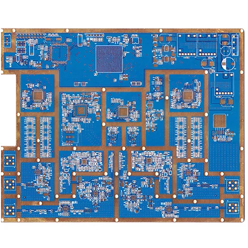
1. Product Overview: What Is a High Frequency Hybrid PCB?
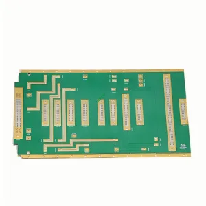
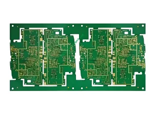
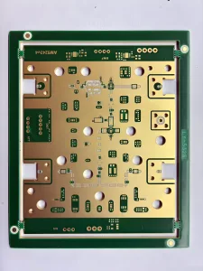
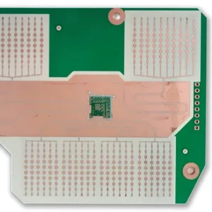
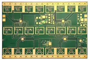
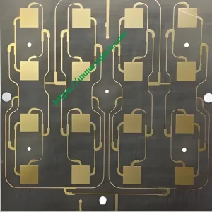
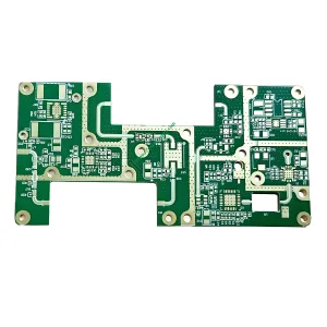
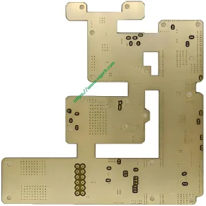
A high frequency hybrid PCB integrates Rogers RO4350B high-frequency laminates with standard FR4 materials within a single multilayer board through precision lamination.
UGPCB offers a 12-layer high frequency hybrid PCB built with Rogers RO4350B and FR4. The finished board thickness is 1.6mm with 1OZ finished copper. Characteristic impedance is precisely controlled at 50Ω. This board serves RF/microwave and mixed-signal applications that demand both high-frequency performance and cost efficiency.
Why choose a hybrid design? In 5G base stations, automotive radar, and high-speed communication modules, RF circuits need Rogers low-loss materials for signal integrity. Digital control circuits, power management, and interfaces work perfectly well with standard FR4 at much lower cost. A full Rogers board costs 3 to 8 times more than FR4. A full FR4 board cannot meet RF performance requirements. The high frequency hybrid PCB strikes the optimal balance between performance and cost.
2. Product Classification and Standards Compliance
2.1 Classification by Material Combination
This product is a hybrid laminate PCB – combining Rogers RO4350B (high-frequency layers) with FR4 (digital/power layers) through precision pressing. Under IPC-4101, Rogers RO4350B is a hydrocarbon/ceramic-filled glass-reinforced laminate. FR4 is a flame-retardant epoxy woven glass fabric copper-clad laminate.
2.2 Classification by IPC-6012 Performance Class
Per IPC-6012, this board meets Class 2 (dedicated service electronic products) and Class 3 (high-reliability electronic equipment) requirements.
2.3 Classification by Frequency Range
This is an RF/microwave frequency PCB. The Rogers RO4350B layer maintains a stable dielectric constant of 3.48±0.05 at 10GHz, suitable for 500MHz to millimeter-wave frequency designs.
3. Core Materials and Key Performance Parameters
3.1 Rogers RO4350B – The “Gold Standard” for High-Frequency Layers
Rogers RO4350B is a patented hydrocarbon resin system with ceramic filler, reinforced with woven glass fabric. Key advantages include:
- Dielectric Constant (Dk): 3.48 ± 0.05 @ 10GHz (process value), 3.66 (design value). FR4 typically has ±5% to 10% Dk variation. RO4350B offers only ±1.4% tolerance, providing a solid foundation for precise impedance control.
- Dissipation Factor (Df): 0.0037 @ 10GHz – significantly lower than FR4, ensuring low-loss high-frequency signal transmission.
- Thermal Conductivity: 0.69 W/m·K @ 50°C (ASTM D5470).
- Volume Resistivity: 1.2×10¹⁰ MΩ·cm (IPC-TM-650 2.5.17.1).
- Flame Retardant Rating: UL 94 V-0.
3.2 FR4 – The Cost-Effective Choice for Digital and Power Layers
FR4 is a standard flame-retardant epoxy woven glass fabric laminate. It offers low cost, mature processing, and high mechanical strength. It works well for digital circuits, power distribution, and ground layers.
3.3 12-Layer Hybrid Stackup Structure
This product uses a 12-layer hybrid stackup. The outer layers and critical RF signal layers use Rogers RO4350B cores. Inner layers use FR4 cores for power, ground, and low-speed digital signals. Total board thickness is 1.6mm. Finished copper thickness is 1OZ (35μm).
3.4 Key Performance Parameter Summary
| Parameter | Specification | Test/Reference Standard |
|---|---|---|
| Laminate | Rogers RO4350B + FR4 | — |
| Layer Count | 12 layers | — |
| Finished Board Thickness | 1.6mm | IPC-6012 |
| Finished Copper Thickness | 1OZ (35μm) | IPC-6012 |
| Characteristic Impedance | 50Ω | IPC-2141 / IPC-2251 |
| Dielectric Thickness | 0.508mm | — |
| Dielectric Constant (Dk) | 3.48 ± 0.05 @ 10GHz | Rogers RO4350B Datasheet |
| Thermal Conductivity | 0.69 W/m·K @ 50°C | ASTM D5470 |
| Flame Retardant Rating | UL 94 V-0 | UL 94 |
| Volume Resistivity | 1.2×10¹⁰ MΩ·cm | IPC-TM-650 2.5.17.1 |
4. Design Considerations: Four Core Principles for High Frequency Hybrid PCBs
4.1 Impedance Control – Achieving the 50Ω Target
Impedance control is central to high frequency PCB design. The 50Ω standard is the most widely used impedance in RF systems. This product maintains impedance at 50Ω to ensure maximum power transfer and minimum signal reflection.
Impedance precision depends on dielectric thickness, dielectric constant, and trace width. RO4350B’s ±1.4% Dk tolerance offers a clear advantage over FR4’s ±5% to 10% variation. A critical note: because RO4350B has a lower Dk, signal trace widths on Rogers layers must be approximately 10% to 15% wider than on FR4 layers for 50Ω designs. Additionally, a ±0.5mil variation in dielectric thickness can shift impedance by approximately ±2Ω on a 10mil Rogers microstrip line – making precise thickness control essential.
4.2 Stackup Design – Balancing Performance and Cost
Stackup design affects signal integrity, power integrity, EMC performance, and impedance control complexity. This 12-layer stackup follows these principles:
- RF signal layers are placed on outer Rogers RO4350B layers using microstrip structures to minimize transmission loss.
- Ground and power layers are placed on FR4 layers, providing stable reference planes.
- Layer symmetry maintains mechanical balance to prevent warpage.
- Material compatibility – RO4350B can be processed using the same methods as FR4, eliminating the special via treatments required for PTFE-based materials.
4.3 Thermal Management – 0.69 W/m·K Heat Dissipation
This product achieves 0.69 W/m·K thermal conductivity. In PCB thermal management, thermal conductivity k (W/m·K) measures how efficiently a material transfers heat. RO4350B’s 0.69 W/m·K significantly outperforms standard FR4 (approximately 0.25 to 0.3 W/m·K), enabling more effective heat dissipation from high-power RF devices.
4.4 Dimensional Stability – Low CTE Ensures Reliability
RO4350B’s Z-axis coefficient of thermal expansion (CTE) is 32 ppm/°C (-55°C to 288°C). This closely matches copper’s CTE (approximately 17 ppm/°C), ensuring plated through-hole (PTH) reliability under thermal cycling. X and Y axis CTE values are 10 ppm/°C and 12 ppm/°C respectively. The glass transition temperature (Tg) exceeds 280°C, maintaining stable expansion characteristics across all processing temperatures.
5. Working Principle: How Do High-Frequency Signals Travel in a Hybrid PCB?
In high-frequency circuits, signals propagate as electromagnetic waves rather than simple “0” and “1” logic levels. The high frequency hybrid PCB operates through several mechanisms:
Signal Transmission: High-frequency signals travel in microstrip or stripline structures on the RO4350B layer. RO4350B’s low Dk (3.48) and low Df (0.0037) ensure signals propagate with minimal insertion loss.
Impedance Matching: Precise control of trace width, dielectric thickness, and dielectric constant sets characteristic impedance at 50Ω. This matches the source, transmission line, and load – maximizing power transfer and minimizing signal reflection.
Interlayer Interconnection: High-frequency signal layers (Rogers) connect to digital/power layers (FR4) through plated through-holes (PTH). RO4350B’s low Z-axis CTE (32 ppm/°C) ensures PTH reliability during thermal cycling.
Thermal Management: Heat from high-power RF devices conducts through the RO4350B layer (0.69 W/m·K) to the FR4 layers and external heat dissipation structures, keeping devices within safe operating temperatures.
6. Manufacturing Process: From Materials to Finished 12-Layer Hybrid Board
6.1 Incoming Material Inspection
Inspect Rogers RO4350B and FR4 cores. Verify dielectric constant, thickness, copper foil quality, and other parameters against IPC-4101 and Rogers datasheet requirements.
6.2 Inner Layer Circuit Fabrication
Process circuit pattern transfer, etching, and AOI inspection on FR4 inner layers (for power and ground).
6.3 Brown Oxide Treatment
Apply brown oxide treatment to inner layer copper surfaces to enhance layer adhesion.
6.4 Layup and Lamination
This is the most critical step in hy hybrid PCB manufacturing:
- Stack Rogers cores, FR4 cores, and prepreg according to the designed 12-layer stackup.
- Use stepped lamination to prevent stress and dimensional distortion caused by CTE differences between Rogers and FR4.
- Optimize prepreg selection (e.g., low-flow prepreg) and lamination parameters to minimize interlayer stress.
6.5 Drilling and Desmear
Perform mechanical drilling and laser drilling (for blind/buried vias if required). Follow with desmear and preparation for hole metallization.
6.6 Hole Metallization and Plating
Apply electroless copper deposition and electrolytic copper plating to achieve 1OZ (35μm) finished copper thickness.
6.7 Outer Layer Circuit Fabrication
Create RF signal traces on Rogers outer layers. Strictly control trace widths to ensure 50Ω impedance accuracy.
6.8 Solder Mask and Surface Finish
Apply solder mask ink and surface finish (e.g., ENIG) to ensure solderability and oxidation resistance.
6.9 Electrical Testing and Final Inspection
Perform 100% electrical testing (including impedance testing and continuity testing). Conduct visual inspection, dimensional measurement, and reliability sampling.
7. Performance Advantages: Why Choose UGPCB’s 12-Layer High Frequency Hybrid PCB?
7.1 Superior High-Frequency Performance
RO4350B delivers Dk = 3.48±0.05 @ 10GHz and Df = 0.0037 @ 10GHz. These properties ensure low-loss, low-dispersion signal transmission from 500MHz to millimeter-wave frequencies.
7.2 Precise 50Ω Impedance Control
The ±1.4% Dk tolerance, combined with precise dielectric thickness control, enables high-accuracy 50Ω characteristic impedance – meeting the impedance matching requirements of RF systems.
7.3 Excellent Cost-Performance Ratio
Compared to a full Rogers solution, the Rogers-FR4 hybrid solution saves approximately 60% to 70% in material costs while delivering significantly better RF performance than a full FR4 design.
7.4 Reliable Mechanical and Thermal Performance
- UL 94 V-0 flame retardant rating
- Z-axis CTE of only 32 ppm/°C
- Tg > 280°C
- Thermal conductivity of 0.69 W/m·K
7.5 Compatible with FR4 Processing
RO4350B can be processed using the same methods as standard FR4. No special via treatments or handling procedures are required – reducing manufacturing costs and shortening lead times.
8. Typical Applications
8.1 5G Communication Base Stations
Antenna arrays and RF front-ends (power amplifiers, low-noise amplifiers) require RO4350B layers for low-loss RF connections. Baseband processors and digital interfaces can be placed on FR4 layers.
8.2 Automotive Millimeter-Wave Radar (77GHz)
Feed networks between transmit/receive antennas and transceiver chips use Rogers materials for precise phase consistency. Radar controllers and CAN bus interfaces use FR4 layers.
8.3 Satellite Communications and Microwave Point-to-Point Transmission
Applications include cellular base station antennas and power amplifiers, microwave point-to-point (P2P) links, and satellite direct-to-home low-noise block (LNB) downconverters.
8.4 High-Speed Optical Modules and Wired Communications
In 400G optical module driver boards, high-speed SerDes differential pairs (≥56 Gbps PAM4) require low-loss substrates to maintain eye diagram quality. FPGA logic and DDR memory can use FR4.
8.5 RFID and Wireless Sensing
Applications include RFID tags, wireless data acquisition systems, wireless remote controls, and telemetry systems.
9. Why Choose UGPCB?
UGPCB has extensive experience in high-frequency material properties and hybrid processing – covering process control, copper plating, lamination schemes, RF trace tolerances, and impedance parameter control. We commit to:
- ✅ 100% electrical testing (including impedance testing)
- ✅ Strict compliance with IPC-6012 and IPC-4101 standards
- ✅ Full process quality traceability
- ✅ Professional engineering team providing DFM (Design for Manufacturability) support

10. Inquire Now – Get Your Custom Solution
UGPCB’s 12-layer Rogers RO4350B+FR4 high frequency hybrid PCB is your optimal solution for 5G communications, automotive radar, satellite communications, and high-speed optical modules – balancing performance and cost.
📧 Send your inquiry now. Our RF PCB engineering team will respond within 24 hours with:
- Customized stackup design proposals
- Precise 50Ω impedance control calculations
- Competitive volume pricing
- DFM manufacturability optimization recommendations
Make UGPCB your trusted partner for high frequency hybrid PCB projects!