
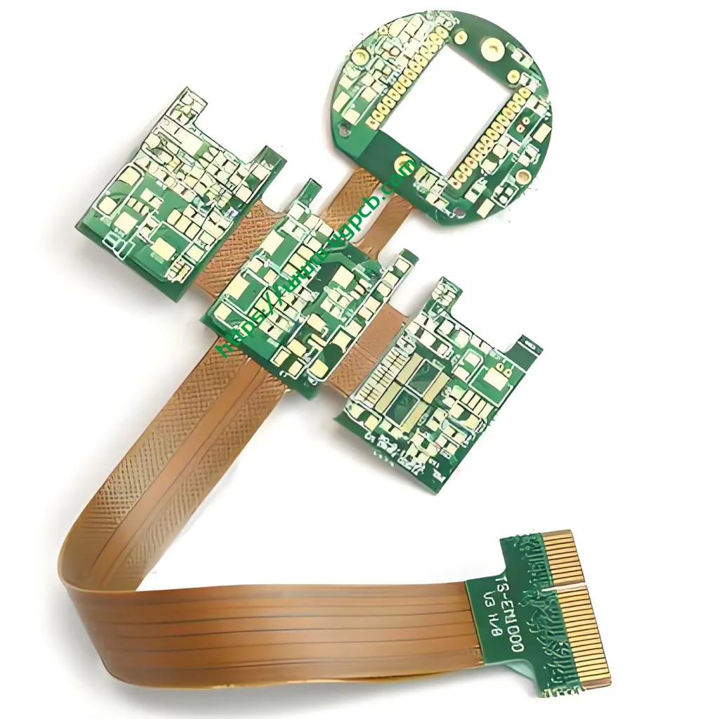
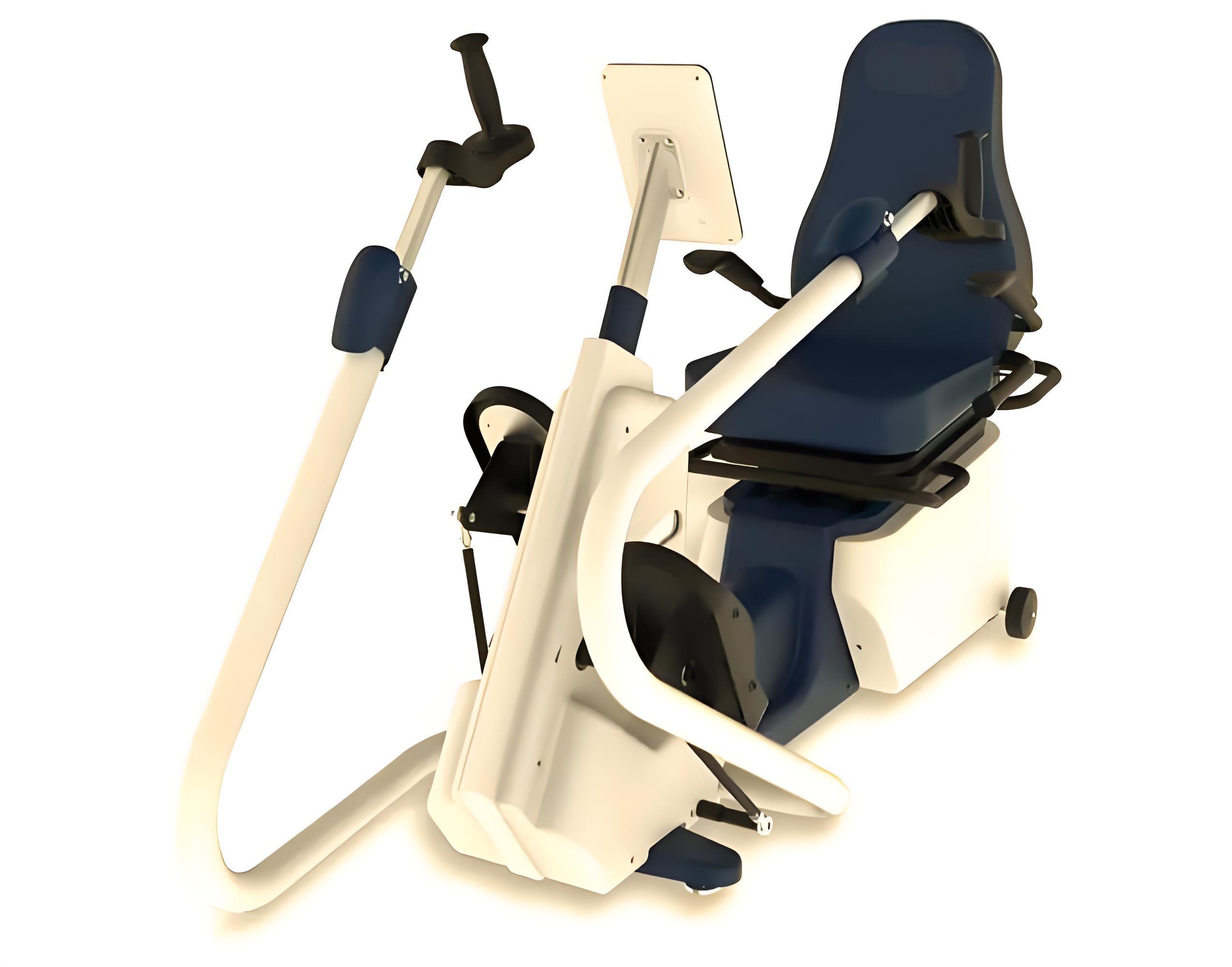
This high-precision 6-layer rigid-flex PCB is built for smart health assistants, wearable medical devices, and portable patient monitors. UGPCB™ integrates rigid FR-4 and flexible polyimide (PI) into one robust module. This design removes internal connectors and cables. It lowers failure points and boosts system stability.
Product Overview
The UGPCB Smart Health Assistant Rigid-Flex PCB belongs to IPC 6013 Type 4 (multi-layer rigid-flex board with plated through holes). The rigid layer uses FR-4 epoxy glass fabric. The flexible layer uses polyimide (PI). This combination offers high reliability, thin profile, and 3D integration.
Market data shows the global smart wearable health device market reached $28.6 billion in 2025. China’s market alone hit $4.53 billion. China’s medical PCB market grows at 5.2% CAGR, second only to aerospace. In this fast-growing field, high-accuracy rigid-flex PCBs become the core interconnect solution for smart health devices.
UGPCB provides full-service support: PCB design, prototyping, and volume production. We help shorten your product development cycle, lower manufacturing costs, and improve reliability.
Scientific Classification & Definition
Definition: A rigid-flex printed circuit board (also called rigid-flex PCB or FPCB) combines rigid and flexible substrates into one structure. It contains one or more rigid areas (for components and mechanical support) and one or flexible areas (for bending and folding in compact devices).
IPC Classification: IPC-6013 Type 4 – Multi-layer Rigid-Flex Board with rigid multilayer and flexible multilayer sections.
| Parameter | Description |
|---|---|
| IPC Type | IPC 6013 Type 4, with PTH |
| Medical Grade | Class 2/Class 3, ISO 13485 compliant |
| Flex Area Use | Static bend (formed once during assembly) |
| Layer Stack | 6-layer hybrid: 6 interconnects in rigid + multi-layer in flex |
| Surface Finish | ENIG per IPC-4552 (Gold 0.025–0.125μm, Nickel 3–6μm) |
Core Parameters & Materials
| Parameter | Specification | Standard |
|---|---|---|
| Model | Smart Health Assistant Rigid-Flex PCB | – |
| Layer Count | 6 | IPC-6013 Type 4 |
| Rigid Material | FR-4 (epoxy glass fabric) | IPC-4101 Class B/L |
| Flex Material | Polyimide (PI) | IPC-6013D |
| Rigid Thickness | 0.8mm | – |
| Flex Thickness | 0.2mm | – |
| Copper Thickness | 0.025mm (approx. 0.7 oz/ft²) | – |
| Surface Finish | Immersion Gold / ENIG | IPC-4552 |
| Min Trace/Space | 0.1mm (4 mil) | IPC-2221 |
| Solder Mask Color | Green / White (optional) | – |
| Application | Smart health assistants, wearables, portable monitors | – |
Material Details:
-
FR-4 (Rigid): Glass-reinforced epoxy laminate. Tg ≥130°C. CTE 12–16 ppm/°C. Excellent mechanical strength, chemical resistance, and insulation (≥10¹²Ω at 500V DC). It is the industry standard rigid substrate for medical PCBs.
-
Polyimide (Flex): PI film with Tg >300°C. Operates from -55°C to +300°C. Minimum bend radius 0.1mm. Dynamic flex life ≥50,000 cycles. PI offers outstanding thermal stability and flexibility.
-
Copper (0.025mm / 0.7 oz): Balances current capacity and fine-line etching. According to IPC-2221, a 0.1mm trace (outer layer, 10°C temperature rise) carries about 100–150mA – sufficient for most medical sensor signals.
Working Principle
The rigid-flex PCB works through coordinated interconnection and signal transmission between rigid and flexible zones.
Rigid zone: Six copper layers stack and laminate on FR-4. Plated through holes (PTH) provide vertical interconnects. You solder or mount components on the rigid surface. This forms the core circuit system: microcontroller (MCU), power management IC (PMIC), Bluetooth/WiFi module, etc. The rigid zone gives stable mechanical support for reliable soldering.
Flexible zone: The polyimide substrate carries bendable signal traces. A coverlay protects the copper circuits. The flex zone bends, folds, or twists to connect sensors (heart rate, blood oxygen, accelerometer). This allows 3D signal routing. Impedance remains continuous along the flex, ensuring lossless transmission of high-frequency physiological signals like ECG and PPG.
Design Guidelines (IPC-2221 & IPC-2223)
Follow these key rules when designing your smart health assistant rigid-flex PCB:
-
Stack-up design: Use a mirror-symmetric 6-layer rigid stack (e.g., Top-GND-Signal-Power-GND-Bottom). Keep warp below 0.75%. For the flex area, use 2–4 layers maximum to retain bending flexibility.
-
Trace/space: Minimum 0.1mm (4 mil) for standard signals per IPC-2221. For high-speed differential pairs (I²C, SPI, RF), use 0.15mm to improve impedance matching.
-
Bending area routing: Use arcs and angled traces – never 90° corners – to avoid stress concentration. For dynamic flex, use 0.5 oz copper (thinner than 0.7 oz) to extend flex life.
-
Impedance control: Control high-speed signals (≥1 GHz) to ±10% tolerance. Adjust trace width and layer spacing. Target 50Ω single-ended or 90/100Ω differential. For ECG signals (low frequency, high impedance), ensure input impedance >10MΩ.
-
Thermal management: Smart health devices are compact and heat-dense. Add copper pour or thermal vias under power modules – copper area at least 1.5x the component area. Keep hot components at least 5mm away from temperature sensors to avoid thermal interference.
UGPCB offers a free DFM review. We check your rigid-flex design against IPC standards and manufacturability. [Submit your design files for free review →]
Structure & Components
The smart health assistant rigid-flex PCB has three core parts:
-
Rigid zone (6-layer FR-4, 0.8mm total): Holds large components: MCU, Bluetooth/WiFi module, PMIC, battery connector. Components attach via SMT.
-
Flexible zone (0.2mm polyimide): Connects rigid zones to sensors. Bends and folds for 3D assembly. Coverlay protects copper traces.
-
Transition zone (rigid-flex interface): No-flow prepreg bonds FR-4 and PI layers layer by layer. Critical alignment tolerance: ≤±0.05mm.
Performance & Standards Compliance
| Standard | Description | Key Requirement |
|---|---|---|
| IPC-2221 | Generic PCB design | Min trace/space ≥0.1mm, insulation resistance ≥10¹²Ω |
| IPC-6013 Type 4 | Flexible/rigid-flex qualification | Peel strength ≥0.6N/mm, dynamic flex ≥50,000 cycles |
| IPC-4552 | ENIG specification | Gold 0.05–0.23μm, Nickel 3–6μm |
| IPC-6012 | Rigid PCB qualification | Trace tolerance ±0.03mm, hole position deviation ≤0.05mm |
| J-STD-003C | Solderability test | 288°C solder bath for 10 seconds, no delamination or blistering |
| ISO 13485 | Medical quality management | Process control for medical-grade PCBs |
| UL 94 V-0 | Flammability rating | FR-4 base material – highest V-0 rating |
Current capacity (reference IPC-2221): For a 0.2mm wide, 0.025mm (0.7 oz) outer layer trace at 25°C ambient with 10°C rise, capacity is about 0.25–0.3A (empirical). Design with 30% margin – target 0.2A max operating current.
Surface Finish: ENIG (Immersion Gold)
UGPCB uses ENIG per IPC-4552.
-
Gold thickness: 0.025–0.125μm (1–5 microinches). We lock at 0.05μm – ensures solderability, oxidation resistance, and low contact resistance.
-
Nickel thickness: 3–6μm (118–236 microinches). This diffusion barrier prevents brittle intermetallic formation between copper and gold.
-
Key benefit: Excellent flatness (±15μm). Ideal for fine-pitch packages (BGA, CSP) and aluminum wire bonding.
ENIG resists corrosion from sweat, alcohol gel, and biological residues. It passes 72-hour salt spray test with no rust.
Manufacturing Process Flow
-
PI flex material cut → 2. Drill through holes & plasma clean → 3. Electroless copper / PTH → 4. Circuit pattern (dry film/etch) → 5. AOI inspection → 6. Laminate (FR-4 + PI) → 7. Secondary drill (rigid zone) → 8. Outer layer circuit → 9. Solder mask (green/white) → 10. ENIG surface finish → 11. Routing / V-cut / depanel → 12. Electrical test (flying probe/fixture) → 13. Final QC → Vacuum pack
Features & Advantages
-
3D integration saves space: Flex area bends and folds, reducing device volume by 30–50%. No board-to-board connectors or cables.
-
High reliability: Fewer connectors and solder joints lower system failure rate by over 60%. Dynamic flex life >50,000 cycles.
-
Precision manufacturing: Minimum trace/space 0.1mm (4 mil). Layer-to-layer misalignment ≤±0.05mm. Meets IPC Class 3 high-reliability standard.
-
Medical-grade surface finish: ENIG passes 72-hour salt spray and solder aging tests for long-term durability.
-
One-stop service: Quick-turn prototypes in 3–7 days. Volume production in 10–15 days. Full traceability and sample retention.
Application Scenarios (Smart Health Assistant Rigid-Flex PCB)
-
Smart health watches (ECG, blood pressure, SpO₂ monitoring)
-
Continuous glucose monitors (CGM)
-
Portable ECG patches / cardiac monitors
-
Smart temperature patches / wearable thermometers
-
Smart rehabilitation and nursing devices
-
Home-use multi-parameter health check stations
Why Choose UGPCB?
UGPCB has over 10 years of high-end PCB manufacturing experience. We hold ISO 9001, ISO 13485, and UL certifications. We offer full-process service: PCB fabrication, component sourcing, SMT assembly, and PCBA functional testing.
Is your smart health assistant device struggling with space limits, short flex life, or connector failures? Contact UGPCB for a custom rigid-flex PCB solution.
📧 Email: sales@ugpcb.com
🌐 Website: www.ugpcb.com
📞 Technical hotline: +86 755-27211481
When sending an inquiry, please provide our engineering team with: Gerber files / PCB design requirements / smart health assistant device type / estimated annual volume.
For a free DFM analysis report, email your design files. UGPCB’s engineering team will respond within 24 hours with process optimization advice and cost reduction proposals.
*(Data sources: IPC-2221, IPC-6013 Type 4, IPC-4552; market data from CSRankings, Zhiyan Consulting, Future Market Report)*


