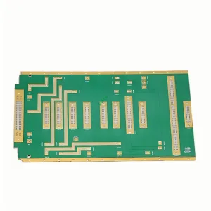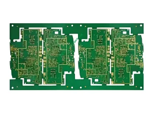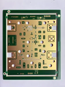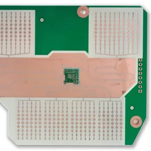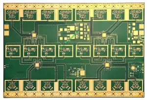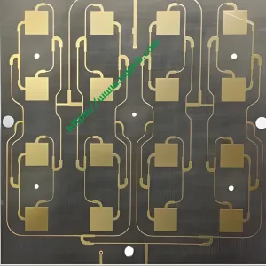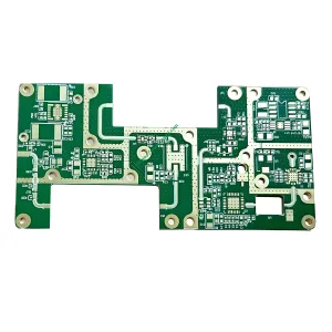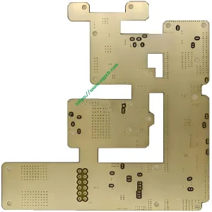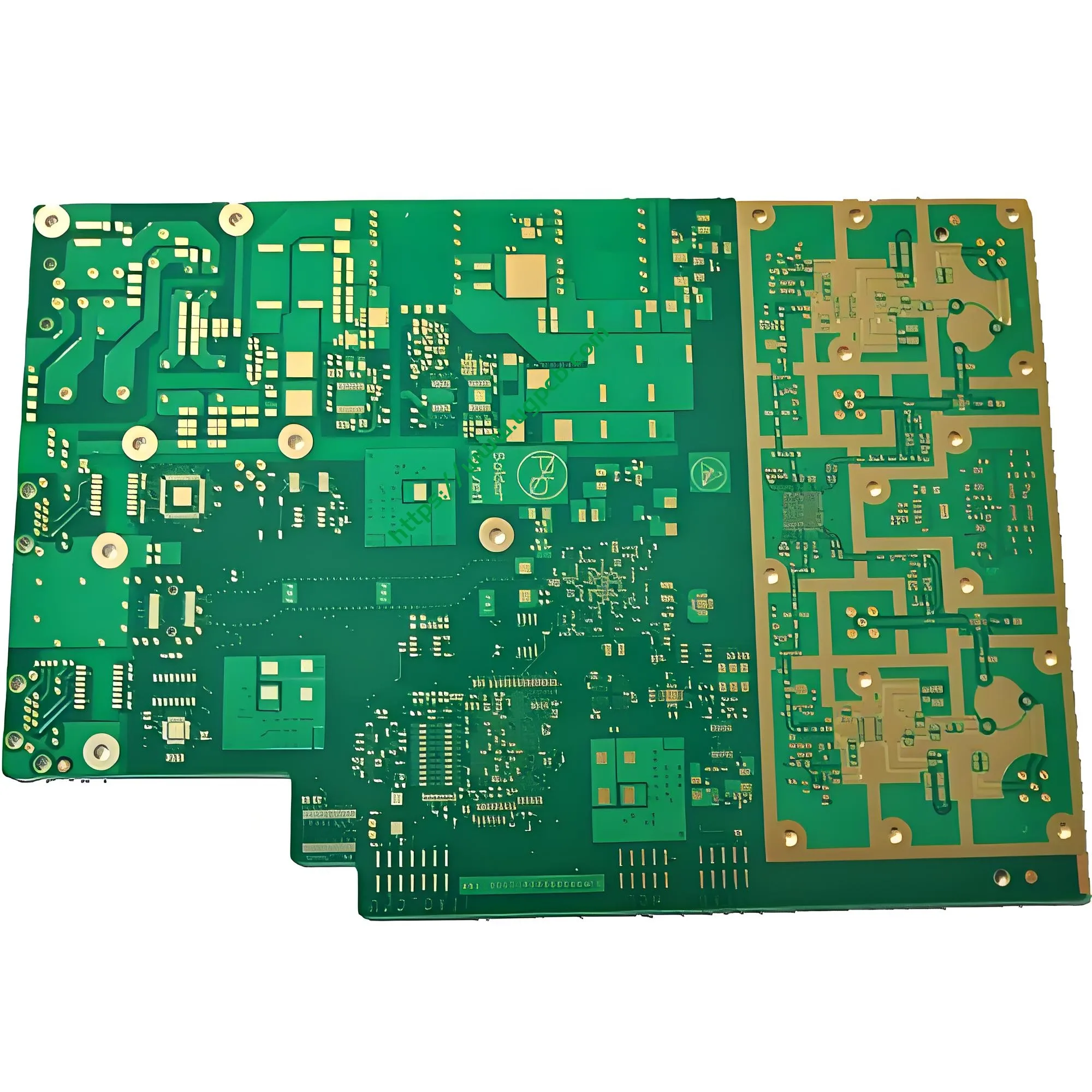
As RF front-ends and high-speed digital circuits continue to converge, PCB design engineers face a classic dilemma. A pure FR4 board suffers excessive signal loss and poor controle de impedância em altas frequências. A full-board Rogers solution delivers excellent RF performance, but it costs much more and limits manufacturability. O 6-layer high-frequency hybrid board solves this trade-off with a smart mixed-dielectric design.
1. Produto Visão geral
UGPCB's 6-camada híbrida de alta frequência PCB usa Rogers RO4350B e FR4 materials in a mixed stack. O acabamento superficial é Imersão Ouro (CONCORDAR). This board targets ETC (Electronic Toll Collection) system control boards and other 5.8GHz RF applications. It achieves precise 5/4 MIL trace width and spacing for high-density RF routing. UM 5-6 layer blind via structure optimizes signal paths.
2. What Is a High-Frequency Hybrid PCB?
A high-frequency hybrid PCB, also called a mixed-dielectric multilayer board, combines two or more different substrate materials in one board. The high-frequency layers use low-loss Rogers material (like RO4350B). The non-critical layers and digital/power layers use more economical FR4.
This hybrid approach places premium material only where RF performance matters – for example, on the top layer where microstrip or coplanar waveguide carries 5.8GHz signals. The other signal layers, aviões terrestres, and power layers use FR4. Compared to a full-Rogers board, the hybrid design cuts material cost by 40–60% while keeping almost the same RF performance.
3. Principais parâmetros técnicos
| Parâmetro | Especificação |
|---|---|
| Número de camadas | 6 |
| Mixed materials | Rogers RO4350B + FR4 |
| Acabamento superficial | Imersão Ouro (ENIG per IPC-4552A, Ni 3–6μm / Au 0.04–0.1μm) |
| Product feature | High-frequency hybrid board |
| Aplicativo | ETC system control board |
| Processo especial | Blind vias between layers 5 e 6 |
| Largura do traço / espaçamento | 5/4 MIL |
| Hole-to-board thickness ratio | 1:10 |
4. Rogers RO4350B High-Frequency Material Properties
The RF performance of this hybrid board relies on accurate use of Rogers RO4350B. Key electrical and thermal characteristics (fonte: Rogers Corporation datasheet, tested per IPC-TM-650) estão listados abaixo.
-
Constante dielétrica (Dk): 3.48 ±0,05@ 10 GHz (process reference); 3.66 @ 10 GHz (design reference for thickness >60mil)
-
Fator de dissipação (Df): 0.0037 @ 10 GHz
-
Zis Z CTE (coeficiente de expansão térmica): 32 ppm/°C (–55°C to 288°C) – much better than standard FR4, which reduces via cracking risk
-
Condutividade térmica: 0.69 W/m/°K @ 50°C (ASTM D5470)
-
Classificação de inflamabilidade: UL 94 V-0 – meets safety requirements for active devices and high-power RF designs
-
Compatibilidade de processos: No special via preparation needed (unlike PTFE materials); RO4350B processes similarly to FR4, which lowers production cost
Why this matters: The Dk of RO4350B changes very little from 500MHz to 40GHz. This stability allows engineers to design accurate 50Ω or 75Ω impedance transmission lines across a wide bandwidth. For ETC systems operating at 5.8GHz (per GB/T 20851), this means reliable impedance control. Por exemplo, using a microstrip structure with Dk=3.48, board thickness=0.254mm, and 1oz copper, a 5mil trace width achieves 50Ω characteristic impedance per the formula below.
5. How Does a 6-Layer High-Frequency Hybrid Board Work?
The core principle is a layer‑dedicated signal architecture.
-
Camadas de sinal RF (Rogers RO4350B medium) – Located on the top layer or specific inner layers. They carry 5.8GHz ETC communication signals. The stable Dk and low Df of RO4350B keep insertion loss below 0.31dB/cm at 40GHz.
-
Digital/control layers (FR4 medium) – Handle baseband signals, MCU/FPGA logic control, and power management. FR4 brings low cost and good mechanical strength.
-
Reference ground and power layers – A solid ground plane adjacent to RF layers provides a low‑impedance return path and suppresses EMI.
-
5‑6 layer blind vias – Blind vias connect only specific layers (por exemplo, L5 to L6). They reduce parasitic capacitance and inductance compared to through‑hole vias, and they save routing space.
-
Impedance‑matched design – Using the precise Dk value of RO4350B, the controlled impedance (normalmente 50Ω) is calculated with the microstrip formula:
 Onde:
Onde:
-
εr=3.48 (RO4350B Dk)
-
h = espessura dielétrica (milésimos)
-
c = largura do traço (5 milésimos)
-
t= espessura do cobre (milésimos)
Esta fórmula, combined with field solver simulations, ensures accurate 50Ω control.
6. Aplicativos e casos de uso
The primary application of this 6‑layer hybrid PCB is the ETC system control board. It also suits many other 5.8GHz DSRC (dedicated short‑range communication) dispositivos.
-
ETC roadside unit (RSU) placa de controle – RF front‑end transceiver + baseband processing + gerenciamento de energia. ETC follows China national standard GB/T 20851 at 5.8GHz using ASK modulation and DSRC protocol.
-
ETC onboard unit (OBU) main board – Also works at 5.8GHz, with 5µA ultra‑low‑power wake‑up circuit and integrated RF transceiver.
-
5G base station front‑end modules – Mixed integration of microwave signal processing and digital baseband control.
-
Automotive millimeter‑wave radar (24GHz / 77GHz) – RO4350B works reliably up to 40GHz, meeting automotive radar requirements for phase noise and temperature stability.
-
Wi‑Fi 6/7 roteadores – Mixed board for 5–7GHz high‑speed data links with RF front‑end and digital SoC.
-
Satellite communication modules – Low‑cost hybrid integration of high‑frequency receive front‑end and digital demodulation.

7. Classificação do Produto
Por IPC-6018D (Qualification and Performance Specification for High‑Frequency (Microondas) Quadros Impressos), este produto se enquadra nas seguintes categorias.
-
Main class: High‑frequency microwave printed board
-
Subclass: Mixed‑dielectric multilayer – a board that combines two or more substrate materials with different Dk values in one stack
-
Feature class: Multilayer with blind vias – verified through IPC‑6018D test methods
-
Material conformance: Base materials meet IPC‑4101E (Especificação de materiais básicos para placas impressas rígidas e multicamadas) for high‑frequency/high‑speed performance
8. Design Guidelines for High‑Frequency Hybrid Boards
Design engineers must focus on these five critical areas.
-
Stack‑up and material assignment – Decide which layers get Rogers and which get FR4. Also define layer order (Sinal RF, chão, digital signal, poder). Tightly control each layer thickness to ensure impedance accuracy.
-
Correspondência de impedância – Precise 50Ω control is the heart of high‑frequency PCB design. The Dk tolerance of RO4350B (± 0,05) directly affects impedance error. Always run 2D or 3D field solver simulations to verify impedance continuity and signal integrity.
-
Blind via optimization (layers 5–6) – Blind vias connect only specific layers (por exemplo, L5 to L6). They reduce parasitic capacitance Cs and parasitic inductance Ls compared to through vias. Minimize the number of blind vias in high‑frequency signal paths and optimize via placement to avoid impedance discontinuities.
-
CTE matching and hybrid lamination – RO4350B has a CTE that matches copper well (10–12 ppm/°C in X/Y axes). No entanto, FR4 and Rogers behave differently during thermal cycling. Use step‑wise lamination with a dynamic pressure curve to prevent delamination.
-
Integridade do sinal (E) análise – Simulate insertion loss, Crosstalk, reflexão, and timing margin at 5.8GHz. Verify that the link works below the target bit error rate.
9. Processo de fabricação
UGPCB follows a strict 8‑step process to ensure every 6‑layer hybrid board meets the highest quality standards.
-
IQC (incoming quality control) – Inspect raw materials per IPC‑4101E and Rogers’ Dk tolerance (± 0,05).
-
Inner layer imaging – Use LDI (Imagem direta a laser) to achieve 5/4 MIL trace width and spacing.
-
Oxide and lay‑up – Align RO4350B and FR4 layers precisely.
-
Laminação híbrida – Apply a step‑wise temperature profile and dynamic pressure curve to cure both materials together, avoiding delamination and warpage.
-
Perfuração - Laser drill blind vias for layers 5–6 and optionally use back drilling. Maintain the 1:10 hole‑to‑board thickness ratio within tolerance.
-
Desmear, cobre sem eletrólito, and panel plating – Ensure reliable copper coverage in blind via walls per IPC‑6018D Class 3.
-
Outer layer imaging and pattern plating – Create fine outer traces and etch resist.
-
Solder mask and legend – Apply solder mask and print component identifiers.
-
CONCORDAR (Imersão Ouro) acabamento superficial – Deposit Ni (3–6μm) e Au (0.04-0,1μm) per IPC‑4552 A/B.
-
Routing and V‑scoring – Route to final shape and V‑score for depanelization.
-
Teste elétrico - Usar sonda voadora to verify continuity and isolation.
-
FQC and outbound inspection – Sample‑check dimensions and RF performance. All products meet hybrid board quality standards.
10. Quality Certifications and Standards
UGPCB’s 6‑layer high‑frequency hybrid boards fully comply with the following industry standards.
-
IPC‑6018D – Qualification and performance for high‑frequency (microondas) placas impressas, covering mixed‑dielectric multilayers and blind/buried vias.
-
IPC‑4101E – Specification for base materials for rigid and multilayer printed boards, ensuring electrical, térmico, e desempenho mecânico.
-
IPC‑4552A/B – ENIG specification, guaranteeing nickel and gold thickness and uniformity for soldering and wire bonding.
-
UL 94 V-0 – Flammability rating for active devices and high‑power RF designs.
-
IPC‑TM‑650 – Test methods manual, used to measure Dk, Df, and other critical parameters of RO4350B.
11. Why Choose UGPCB for Your 6‑Layer High‑Frequency Hybrid Board?
-
Superior high‑frequency performance – Stable Dk of RO4350B enables precise impedance matching with 5/4 MIL traces and low insertion loss. The RF signal quality matches high‑end microwave boards.
-
Significant cost savings – Hybrid design (Rogers only on RF layers, FR4 elsewhere) cuts material and manufacturing costs by 40–60% compared to a full‑Rogers board.
-
Optimized for ETC systems – The board is tuned for 5.8GHz DSRC communication and follows China GB/T 20851 padrões.
-
Advanced manufacturing capability – Supports 5/4 MIL fine lines, 1:10 hole‑to‑board thickness ratio, and 5‑6 layer blind vias – ideal for high‑density HDI‑like RF designs.
-
IPC‑compliant process – Full IPC process control from IQC to FQC, certified to IPC‑6018D for mixed‑dielectric multilayers.
-
One‑stop service – From design review and prototypes to volume production. Our experienced RF PCB engineers support you at every stage.
12. Get a Quote or Start Your Order
UGPCB has years of experience in high‑frequency hybrid board manufacturing. We have delivered many 6‑layer Rogers+FR4 hybrid PCBs for ETC systems, 5G communication, e radar automotivo.
Order process:
-
Envie seus arquivos de design – Gerber, stack‑up drawing, Bom, and technical requirements.
-
Technical review – UGPCB engineers respond within 24 hours with a DFM report and quotation.
-
Confirm order – Sign the contract and pay the deposit.
-
Produção – IQC → in‑process control → FQC → performance testing.
-
Entrega – Receive board with outgoing inspection report, material certificates, and electrical test report.
📧 E-mail: vendas@ugpcb.com
📞 Telefone: +86 135 4412 8719
🌐 Site: https://www.ugpcb.com/