
Battery Protection PCB: Essential Guardian for Your Battery Safety and Performance
에이 Battery Protection PCB is a crucial integrated 회로 기판 specifically designed to safeguard rechargeable batteries, such as lithium-ion cells. Think of it as an intelligent guardian that continuously monitors the battery’s vital parameters. Its primary role is to manage the charging and discharging processes by controlling voltage, 현재의, 그리고 온도. This vigilant protection prevents dangerous conditions and ensures the battery operates within its safe limits, significantly enhancing both the safety and lifespan of the battery pack. As the heart of modern battery management systems, these specialized PCBs are indispensable in everything from portable electronics to electric vehicles.
What is a Battery Protection PCB? 핵심 정의
그 핵심, 에이 Battery Protection PCB is a meticulously designed 인쇄 회로 기판 that hosts a suite of 전자 구성 요소. These components work in concert to protect the battery from a range of hazardous scenarios:
-
Overcharge Protection: Prevents the battery from exceeding its maximum voltage, which can lead to overheating or even fire.
-
Over-discharge Protection: Stops the battery from being drained below its minimum voltage, a condition that can cause irreversible damage.
-
Overcurrent and Short Circuit Protection: Interrupts the circuit when excessive current flow is detected, protecting both the battery and the device it powers.
-
열 관리: Monitors temperature to prevent operation in extreme hot or cold conditions that could degrade battery health.
Advanced battery protection boards, like the reference design TIDA-00792, even incorporate features like cell balancing to equalize the charge across multiple cells, 그리고 gas gauging to accurately estimate the remaining system runtime.
Key Design Considerations for Battery Protection PCBs
Designing a reliable battery protection circuit board requires careful attention to several critical factors that influence its performance, 내구성, and safety.
재료 선택: The Foundation of Reliability
The most common material for Battery Protection PCBs is FR4, a glass-reinforced epoxy laminate known for its excellent mechanical strength and flame-retardant properties (a must for safety-critical applications). FR4 is a versatile and cost-effective choice that meets stringent safety standards like UL94V-0.
Precision Layout and Manufacturing Tolerances
Given that these PCBs are often used in compact devices, they are typically small PCBs demanding high manufacturing precision. A common specification, as seen in UGPCB’s model, includes:
-
최소 추적/공간: 4밀 (0.1mm). This fine-line circuitry allows for a more compact and densely packed design.
-
완성된 두께: 0.6mm, making the board slim and suitable for space-constrained battery packs.
구성 요소 선택: 성능 및 비용의 균형
The choice of components directly impacts the board’s efficacy and is often categorized for different market segments:
-
Protection ICs: High-end designs may use chips from manufacturers like TI (예를 들어, BQ76940 series), Seiko, or Ricoh. These ICs are the “뇌” that makes protection decisions.
-
MOSFET: These act as the “switch” that disconnects the battery during a fault condition. Selection criteria include low on-resistance and high current-handling capacity (예를 들어, TI’s CSD19536KTT).
-
Passive Components: Resistors and capacitors from reputable brands like TDK are chosen for their high precision and reliability, with capacitors specifically in X5R or X7R materials to avoid capacitance drift.
Robust Surface Treatment
이머젼 골드 (동의하다) is a preferred surface finish for Battery Protection PCBs. It provides a flat surface for reliable soldering, excellent corrosion resistance, and good electrical conductivity, which is crucial for the long-term reliability of the protection circuits.
How Does a Battery Protection PCB Work?
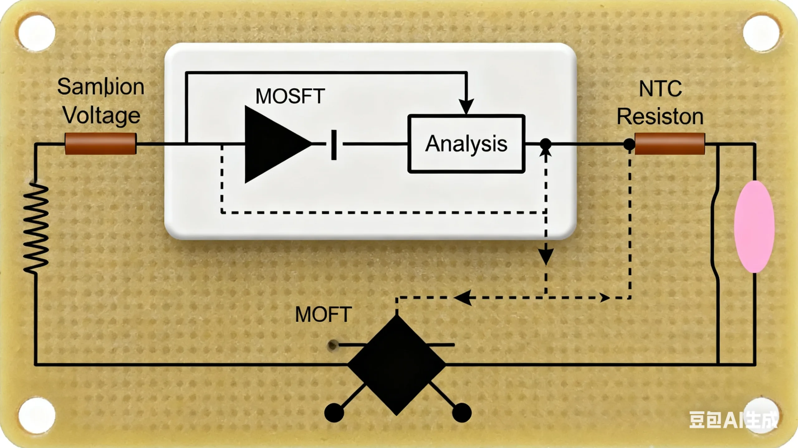
The operation of a Battery Protection PCB is a continuous cycle of monitoring and control, orchestrated by the protection IC.
-
Monitoring: The protection IC constantly measures the voltage across each cell (or the entire pack), the current flowing through the sense resistor, and the temperature via an NTC thermistor.
-
분석: It compares these real-time values against pre-programmed safety thresholds stored in its firmware.
-
제어: If any parameter exceeds its safe limit, the IC takes action by sending a signal to disconnect the MOSFET (the solid-state switches in the circuit). This instantly halts the charge or discharge process, effectively isolating the battery to prevent damage.
-
Balancing (in multi-cell packs): Advanced boards like the TIDA-00792 actively balance cells by shunting a small amount of current from higher-voltage cells to equalize the state of charge across all cells, thereby maximizing the pack’s overall capacity and lifespan.
Applications and Use Cases of Battery Protection PCBs
The application of Battery Protection PCBs is vast and growing, driven by the proliferation of rechargeable batteries. Key sectors include:
-
Electric Vehicles (EVs): Ensuring the safety and longevity of high-voltage battery packs.
-
Smartphones and Consumer Electronics: Protecting the built-in battery from daily charge cycles and potential faults.
-
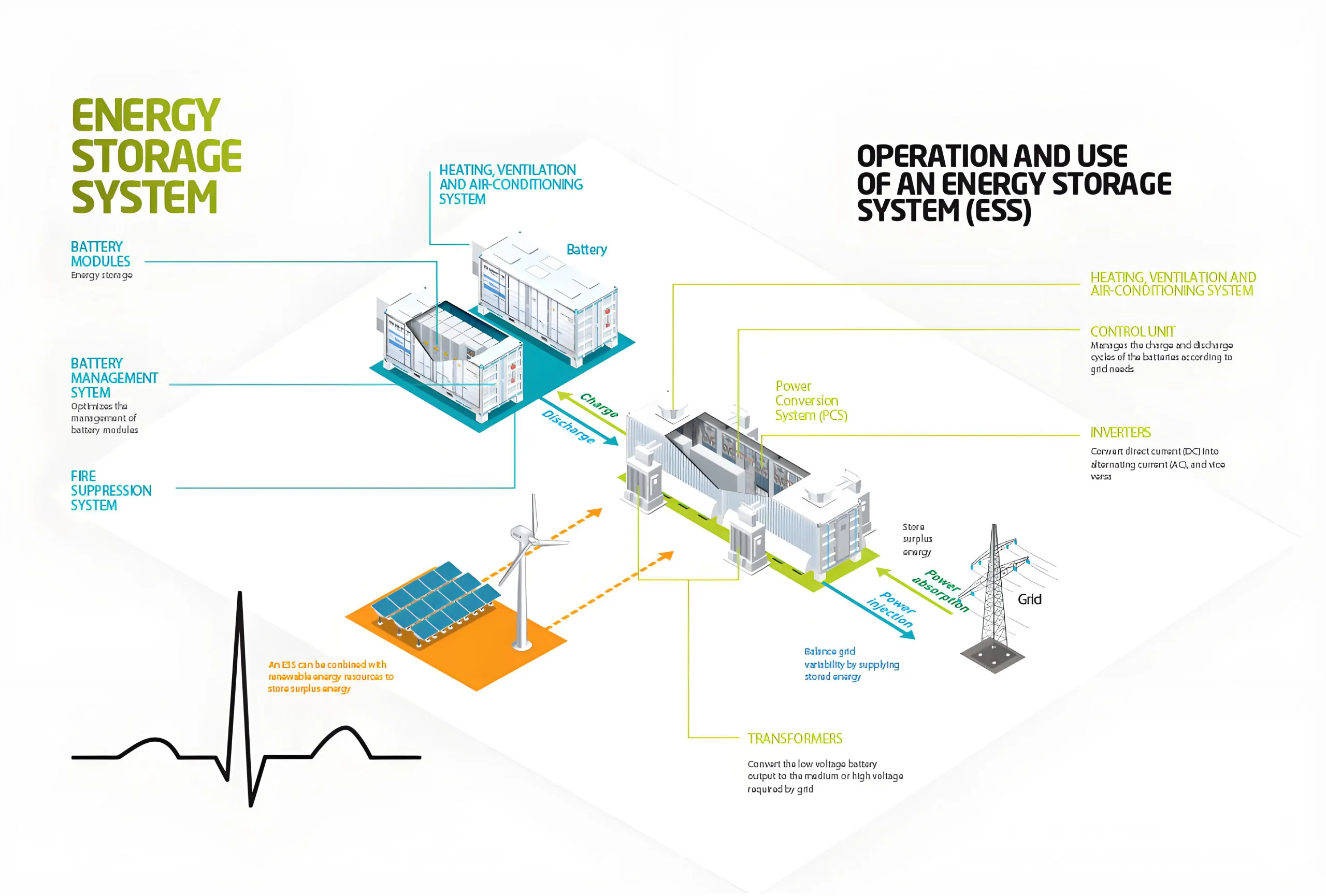
Energy Storage Systems (ESS): Safeguarding large-scale stationary batteries used for solar energy storage and grid stabilization.
-
Drones and UAVs: Providing critical protection for the high-discharge rate batteries used in flight.
-
산업용 장비: Reliable operation in harsh environments for tools and backup power systems.
Classification and Types of Battery Protection PCBs
Battery Protection PCBs can be classified based on their architecture and functionality:
-
Single vs. Dual Protection: 에이 Single Protection Board provides one layer of safety circuits, while a Dual Protection Board incorporates a secondary, independent backup protection layer (like the TIDA-00108 reference design) for high-reliability applications where failure is not an option.
-
By Battery Chemistry: Designed for specific battery types like Lithium-ion, LiFePO4, 등.
-
By Cell Count: Ranging from simple 1-cell protectors to complex stacked architectures for 10-15 cell series batteries.
구조, 성능, and Production of Battery Protection PCBs
Physical Structure and Characteristics
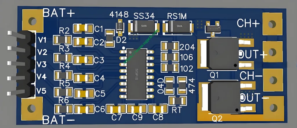
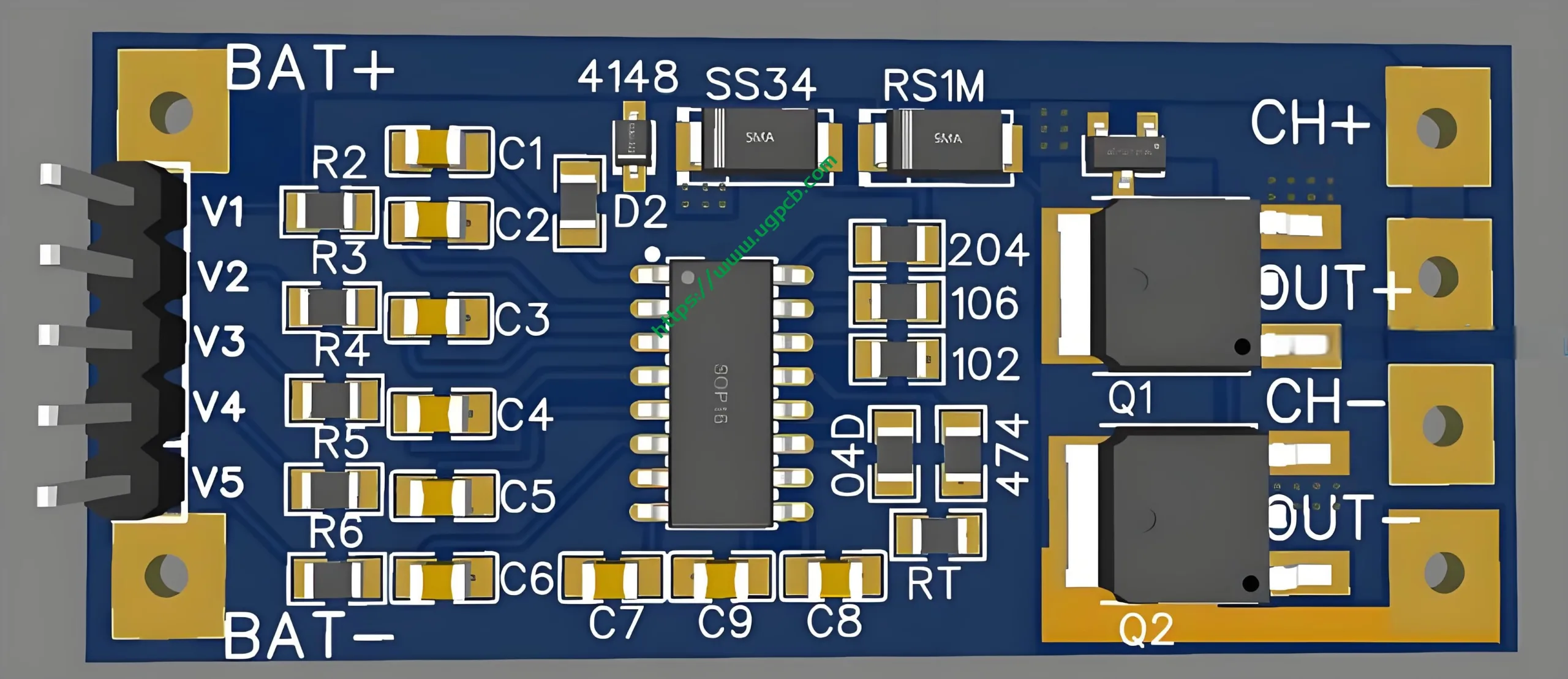
A typical 2-layer Battery Protection PCB, such as the UGPCB 모델, is characterized by its black color, 0.6mm finished thickness, 그리고 1OZ copper thickness. The 2-layer construction allows for a more complex layout of traces on both sides of the FR4 기판, facilitating the routing of power and signal lines separately to minimize interference.
Essential Performance Metrics
Key performance indicators include low internal resistance (often ≤150mΩ for mobile batteries), accurate voltage sensing, fast response time to faults, and low power consumption in standby mode to avoid draining the battery.
Streamlined Production Workflow
The manufacturing of battery protection circuit boards (PCBAS) adheres to the following IPC-compliant process flow:
-
설계 & 치사한 사람: Creating the schematic and layout based on the protection IC’s requirements.
-
재료 준비: Cutting the FR4 copper-clad laminate to size.
-
패턴 이미징: Transferring the circuit pattern onto the board.
-
에칭: Removing unwanted copper to reveal the traces.
-
라미네이션 & 교련: For multi-layer boards; a 2-layer board like the UGPCB model is simpler.
-
표면 마무리: 신청 이머젼 골드 to the pads.
-
솔더 마스크 & 실크 스크린: Applying the black insulating layer and component markings.
-
전기 테스트: Verifying continuity, 격리, 그리고 기능.
-
품질 보증 & 최종검사.

Why Choose UGPCB’s Battery Protection PCB?
UGPCB’s product, with the specifications provided, embodies the key attributes of a high-quality, reliable protection board:
-
Compact and Precise: 와 0.6MM 두께 그리고 4Mil Trace/Space, it is ideal for modern, miniaturized devices.
-
Durable and Reliable: The use of FR4 material and 이머젼 골드 surface finish ensures long-term performance and strong solder joints.
-
Effective Protection: Designed to host critical components that prevent overcharge, over-discharge, and overcurrent, fundamentally extending battery life.
This combination of advanced materials, precise manufacturing, and robust design principles makes UGPCB’s Battery Protection PCB a superior choice for your energy storage solutions.


