
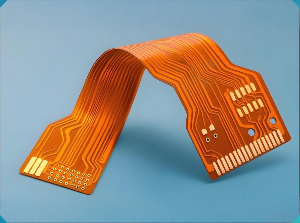
With electronics becoming thinner and foldable, วงจรพิมพ์ที่ยืดหยุ่น (FPCS) are taking center stage. Hinge cables in foldable phones, sensor connections in smartwatches, and flexible displays in car cockpits all demand a perfect balance between bendability and reliability. Yet a harsh reality stands out: industry data shows that over 60% of field failures in flexible circuits come from mechanical stress, not electrical defects.
Designing an FPC is easy. Designing one that meets functional needs and survives repeated bending is hard. This guide covers design rules, core process parameters, การเลือกวัสดุ, quality standards, and procurement decisions. You will learn the key points from design to manufacturing.
1. First Principle of FPC Design: Put Flexibility First
To design FPCs, you must break away from rigid พีซีบี thinking. Every step in flexible circuit design needs validation from manufacturing parameters. The final result is a synergy of design, วัสดุ, and process.
Bend area definition: First decide which areas need bending and which must stay rigid. Bend zones follow different rules than non-bend zones. Do not mix them.
Bending radius – the rule that determines life: According to IPC-2223 (the design standard for flexible printed boards), the minimum bending radius directly affects mechanical life. The core rules are:
- Static bending (fixed after installation, no further movement): Minimum radius R ≥ 6 × FPC thickness.
- Dynamic bending (repeated movement during use): Minimum radius R ≥ 10 × FPC thickness.
For high-reliability consumer products like foldable phones, industry practice often uses stricter rules. Data shows that when the bending radius increases to 100 × flexible layer thickness, dynamic bending life can exceed 200,000 รอบ. One case study: a foldable phone brand used R = 100 × thickness and achieved 100 folds per day for 5 years of use.
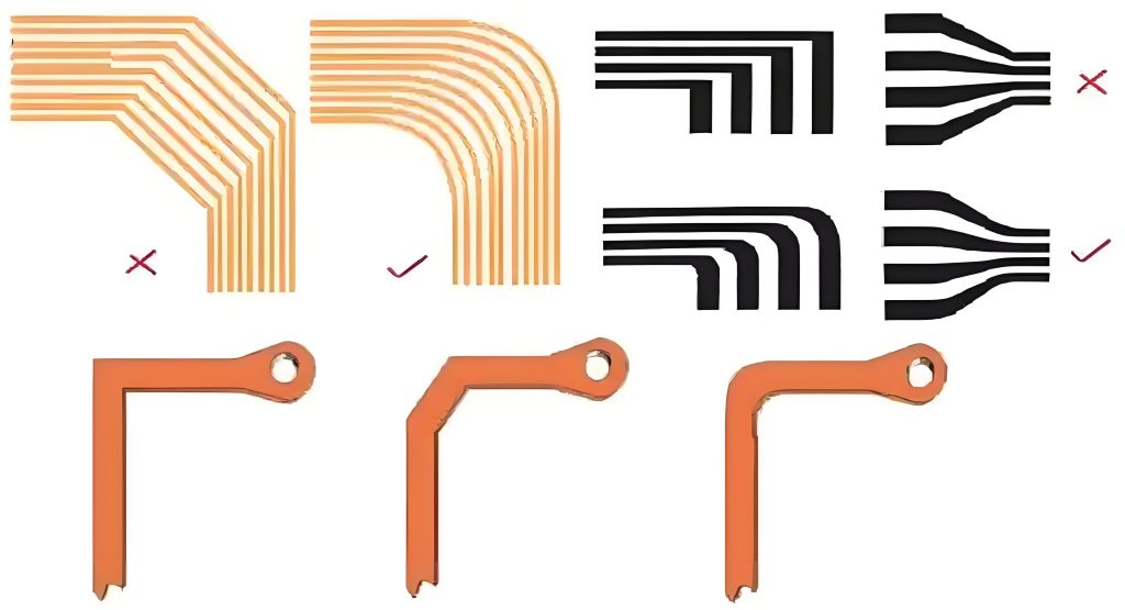
Trace routing rules in bend areas: Run traces perpendicular to the bend axis. This spreads stress across multiple parallel lines. Do not place vias or components in bend areas. Keep line width and spacing at least 0.2 มม / 0.2 มม. Use hatched copper (mesh pattern) in bend areas. It provides good EMI shielding while keeping flexibility.
2. Quick Look at Core FPC Manufacturing Parameters
FPC manufacturing uses many precise steps. The parameters below directly decide product performance and reliability.
| Process Step | Key Parameter | Range / Requirement | มาตรฐาน |
|---|---|---|---|
| การเลือกวัสดุ | PI base layer thickness | 12.5–50 μm | IPC-4204A |
| ฟอยล์ทองแดง | RA copper elongation | ≥15% | IPC-4562B |
| Pattern transfer | Exposure energy | 80–120 mJ/cm² | Industry standard |
| การแกะสลัก | Acidic CuCl₂ temperature | 45±2°ซ, etch factor >3.0 | ไอพีซี-2221 (line width tolerance ±0.03mm) |
| การเคลือบ | Temp / Pressure / Time | 180±5°ซ, 15±2 kg/cm², 60±5 min | IPC-6013 lamination requirements |
| การขุดเจาะ | Minimum mechanical hole | ≥0.1 mm | IPC-2223 via design requirements |
3. Material Selection Decides Success: Why RA Rolled Annealed Copper Is Irreplaceable
When selecting FPC materials, the choice between rolled annealed (RA) copper and electrodeposited (เอ็ด) copper directly determines bending life. According to IPC-4562B (the metal foil standard for printed boards), the two copper types differ greatly in manufacturing and performance.
RA copper foil is made by mechanical rolling. It has a horizontal grain structure, excellent ductility, and low surface roughness. RA foil is ideal for dynamic repeated bending and high-speed signal transmission. FPCs with RA copper can achieve dynamic bend life of over 100,000 รอบ.
ED copper foil is made by electrodeposition. It has a vertical grain structure and poor ductility. ED copper tends to crack at stress points during bending. Use it only for static or one-time bending.
A common mistake: choosing ED copper in dynamic bending to save cost, then seeing mass failures in the field. The correct thinking is: mandatory use RA copper for dynamic bending. For static or low-cycle bending, you may consider ED copper.
Base material also matters: โพลีอิมด์ (PI) can withstand 200–260°C and is the first choice for dynamic bending. Polyester (สัตว์เลี้ยง) handles ≤120°C and costs less, but fits only fixed installations with one-time bending.
4. IPC-6013 Quality Standard: How to Choose Among Three Classes
IPC-6013 is the qualification and performance specification for flexible and rigid-flex printed boards. It defines material requirements, dimensional tolerances, quality consistency tests, and acceptance criteria for FPCs. The standard divides FPCs into three performance classes based on end-use requirements.
| IPC-6013 Class | Application Range | Defect Tolerance | Typical Industries |
|---|---|---|---|
| ระดับ 1 | General electronic products | Highest allowance for cosmetic defects | อุปกรณ์อิเล็กทรอนิกส์สำหรับผู้บริโภค, ไอโอที, toys |
| ระดับ 2 | Dedicated service products | Moderate allowance, tighter dimensional control | การควบคุมอุตสาหกรรม, อุปกรณ์อิเล็กทรอนิกส์ยานยนต์, telecom |
| ระดับ 3 | High-reliability products | Near-zero defects, full traceability | การบินและอวกาศ, อุปกรณ์การแพทย์, ทหาร |
Cost impact: For the same FPC design, ระดับ 3 manufacturing costs 40–80% more than Class 1. The difference comes from much stricter inspection and testing. So match the IPC-6013 class to your actual application. Avoid over-engineering or under-engineering.
For critical applications like automotive electronics, IPC-6013 also sets specific reliability targets. ตัวอย่างเช่น, process capability index (CPK) for key parameters must be ≥1.33. Dynamic bending cycles must be at least 100,000.
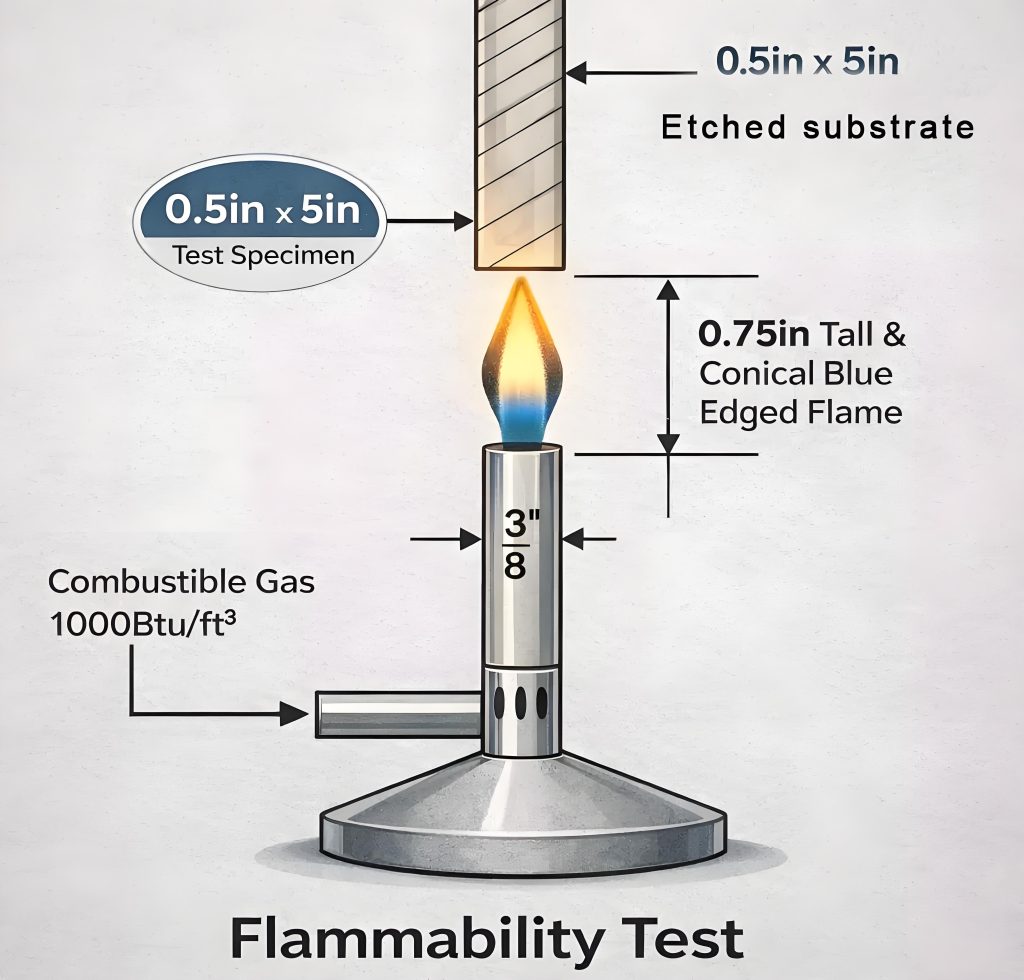
For export products, also check UL 796 safety certification. อล 796 defines construction safety requirements for printed wiring boards. The base material usually needs UL 94 วี-0, the highest flame rating. In the vertical burn test, each sample must have an afterflame time ≤10 seconds, and total afterflame time ≤50 seconds.
5. From Design to SMT Assembly: Process Details You Cannot Ignore
After FPC design and fabrication, several critical process steps remain.
Via protection strategy: Use tented vias (cover the via completely with PI coverlay) for FPCs. Tenting prevents oxidation of the copper inside the hole and stops cracking during bending. Only open vias for test points in non-bend areas when absolutely necessary.
Stiffener design: Add a stiffener in areas where you place connectors or solder components. Common stiffener materials include PI (good for thin flexible boards), FR4 (คุ้มค่า), and steel (high rigidity and support). The stiffener area must precisely avoid pads and vias to prevent interference.
SMT Requirements for Flexible Printed Circuits (FPCS):FPC surface mount assembly requires a dedicated magnetic carrier to maintain board flatness. Prior to SMT, bake the FPC at 80–125°C for 4–8 hours to remove moisture, preventing popcorning (การแยกส่วน) during reflow. The reflow profile shall be set to a peak temperature of 230–245°C, with time above liquidus (TAL) limited to 10 seconds or less.
Panel design: Avoid using mouse bites or V-cuts for FPC panelization. แทน, ใช้bridge connections 0.7–1.0 mm wide. Keep a 5 mm rail on each edge. For boards smaller than 20×20 mm, panelization is strongly recommended.
6. Common Failure Modes and Troubleshooting Guide
| Failure Phenomenon | Possible Cause | สารละลาย |
|---|---|---|
| Trace cracking after bending | Bending radius too small; wrong copper (ED used in dynamic bending); poor bend zone design | Recalculate bending radius; switch to RA copper; move vias out of bend area |
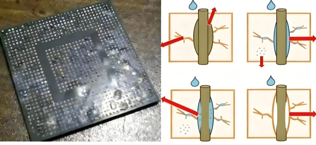
| Coverlay delamination or blistering | Poor lamination control; high humidity during storage; no pre-bake before SMT | Control lamination (Cpk≥1.33); manage warehouse temp/humidity; bake at 125±5°C for 4–6h |
| Pad lifting after soldering | Missing stiffener in solder area; too high or too long soldering | Add FR4 or steel stiffener; optimize reflow profile |
| Tombstone or short on SMT components | Poor FPC flatness; asymmetric pad design | Use magnetic carrier; ensure symmetric and well-sized pads |
7. Material Selection Decision Matrix
| แอปพลิเคชัน | Recommended Base | Recommended Copper | Min Line/Space | Min Dynamic Bend Radius |
|---|---|---|---|---|
| Smartphone / Foldable phone | PI 25 μm | RA copper | 0.075 / 0.075 มม | 5–8 mm |
| Laptop cable | PI 25 μm | RA copper | 0.1 / 0.1 มม | 5–7 mm |
| อุปกรณ์อิเล็กทรอนิกส์ยานยนต์ | PI 50 μm | RA or ED copper | 0.15 / 0.15 มม | 8–12 mm |
| Wearable devices | PI 12.5–25 μm | RA copper | 0.1 / 0.1 มม | 4–6 mm |
| Low-end medical electronics | PET 50–75 μm | ED copper | 0.2 / 0.2 มม | Static use only |
บทสรุป
A successful FPC design starts with deep understanding of material properties. It finishes with full respect for manufacturing processes.
If you are looking for a reliable FPC supplier or need a professional บอร์ด PCB quote, choose a manufacturer with in-house full-process capability and a solid quality system. When evaluating FPC vendors, check: does the supplier own its FPC production line (not outsourced)? Does it offer one-stop prototyping and mass production? Is it certified to IATF16949 or ISO13485?
Whether you need custom FPC flexible circuits or integrated แอสเซมบลี PCBA, selecting the right partner is the first step to project success. To get a quote or ask about technical specifications, prepare your Gerber files and BOM list in advance. This helps the supplier respond quickly.
คำเตือน: The IPC standard data cited in this article comes from publicly available technical documents including IPC-2221, IPC-2223, IPC-6013, IPC-4562, and IPC-TM-650. UL-related data comes from UL 796 and UL 94. Actual design parameters should be based on the manufacturer’s process capabilities and your specific application requirements.
