


I. Descripción general del producto
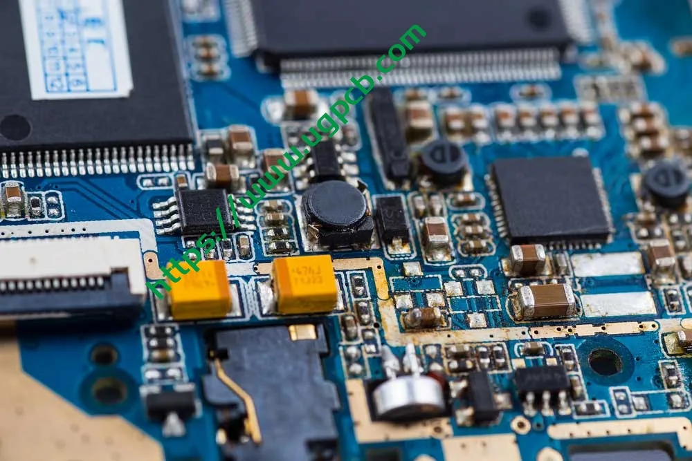
La placa PCB con orificio pasante de doble cara UGPCB es una placa rígida de 2 capas de alto rendimiento. placa de circuito impreso construido sobre un sustrato de vidrio-epoxi FR-4 utilizando un orificio pasante chapado (PTH) tecnología. El tablero mide 86.9 × 73.58 mm con un espesor de 1.0 milímetros, espesor de la lámina de cobre de 1/1 ONZ (35 μm tanto en la capa exterior como en la interior), y una nivelación de soldadura de aire caliente sin plomo. (HASL) acabado superficial. La máscara de soldadura es verde., y la leyenda serigrafiada es blanca.
Una PCB con orificio pasante de doble cara (placa de circuito impreso de doble cara) Cuenta con circuitos conductores en ambos lados del sustrato aislante., con orificios pasantes chapados que permiten la interconexión eléctrica entre las dos capas. En comparación con los PCB de una sola cara, Los PCB de doble cara ofrecen entre un 60% y un 80% más de densidad de enrutamiento y admiten diseños de circuitos más complejos.. UGPCB, respaldado por sistemas de calidad certificados ISO y procesos de fabricación que cumplen con IPC, ofrece PCB de orificio pasante de doble cara de alta calidad y llave en mano tarjeta de circuito impreso Servicios a fabricantes de productos electrónicos en todo el mundo..
II. Definición del producto y especificaciones técnicas
Según IPC-6012F Especificación de calificación y rendimiento para tableros impresos rígidos (publicado en septiembre 2023), La PCB con orificio pasante de doble cara se clasifica como una placa impresa rígida con orificios pasantes chapados. (Tipo 2). Su característica principal es la conexión eléctrica entre conductores en ambos lados a través de paredes perforadas recubiertas de cobre.. UGPCB fabrica este producto en total conformidad con IPC-6012F y cumple con la Clase 2 requisitos de desempeño (equipo electrónico de servicio dedicado).
Especificaciones clave:
| Parámetro | Especificación |
|---|---|
| Material de sustrato | FR-4 (UL retardante de llama 94 V-0) |
| Número de capas | 2 capas (de dos caras) |
| Grosor del tablero | 1.0 milímetros |
| Dimensiones del tablero | 86.9 × 73.58 milímetros |
| Diámetro mínimo del agujero | 0.236 milímetros |
| Ancho mínimo de línea / Espaciado | 0.32 × 0.37 milímetros |
| Espesor de lámina de cobre | 1/1 ONZ (aprox. 35 μm en cada lado) |
| Acabado superficial | HASL sin plomo (Nivelación de soldadura por aire caliente) |
| Máscara de soldadura / Leyenda | Máscara de soldadura verde / Serigrafía blanca |
III. Pautas de diseño
3.1 Selección del material del sustrato: valor técnico del FR-4
FR-4 es una designación de grado retardante de llama establecida por la Asociación Nacional de Fabricantes Eléctricos (NO). las letras “FR” significa retardante de llama, y el numero “4” denota un sistema de resina epoxi reforzado con tejido de vidrio. Para IPC-4101 Especificación de Materiales Base para Tableros Impresos Rígidos y Multicapa, FR-4 Grado A1 representa el nivel de rendimiento principal con resistencia mecánica óptima, propiedades electricas, y confiabilidad a largo plazo.
Indicadores clave de rendimiento del FR-4 (Fuente: IPC-4101 y estándares de la industria):
-
Temperatura de transición vítrea (tg): 130–140°C (estándar FR-4)
-
Constante dieléctrica (Dk) @ 1 GHz: 4.2–4,5
-
Factor de disipación (df) @ 1 GHz: ≤ 0.020
-
Calificación de inflamabilidad: UL 94 V-0
-
Absorción de agua (24 horas): ≤ 0.10%
FR-4 sigue siendo el material de sustrato predominante en la industria de PCB porque ofrece un excelente equilibrio de resistencia mecánica., aislamiento eléctrico, estabilidad dimensional, y procesabilidad.
3.2 Estándares de diseño de circuitos según IPC-2221
Para IPC-2221 Norma genérica sobre diseño de tableros impresos, El diseño del ancho del conductor debe tener en cuenta la capacidad de transporte de corriente., aumento de temperatura, y grosor de cobre. La fórmula de capacidad de carga de corriente IPC-2221 es:
Yo = k · ΔT^0,44 · A^0,725
Dónde:
-
I = Capacidad máxima de transporte de corriente (A)
-
k = constante empírica (0.048 para capas externas, 0.024 para capas internas)
-
ΔT = Aumento de temperatura permitido (°C)
-
A = Área de la sección transversal del conductor (mil²), donde A = W × T
El producto de UGPCB presenta un ancho de línea de 0.32 milímetros (aprox. 12.6 mil), interlineado de 0.37 milímetros (aprox. 14.6 mil), y espesor de cobre de 1 ONZ (35 μm). Para una traza de capa externa con un aumento de temperatura de 10°C:
Una = 0.32 milímetros × 0.035 milímetros = 0.0112 mm² ≈ 17.36 mil²
yo = 0.048 × 10^0,44 × 17,36^0,725 ≈ 0.048 × 2.75 × 7.82 ≈ 1.03 A
Este ancho de conductor soporta aproximadamente 1 una de corriente, Satisfacer las necesidades de transmisión de señal y potencia de la mayoría de los equipos de control industrial y electrónica de consumo.. IPC-2221 recomienda limitar el aumento máximo de temperatura a 10 °C o 20 °C para preservar la vida útil de la PCB.
3.3 Diseño de relación de aspecto y diámetro del orificio
La relación de aspecto de un orificio pasante es una métrica crítica para evaluar la dificultad de perforación y metalización del orificio.. La fórmula es:
Relación de aspecto = Grosor del tablero / Diámetro del agujero perforado
Para el producto de UGPCB con 1.0 mm de espesor del tablero y 0.236 mm diámetro mínimo del agujero:
Relación de aspecto = 1.0 / 0.236 ≈ 4.24:1
Esta relación de aspecto está muy por debajo del límite superior recomendado por la industria de 10:1 y el umbral de diseño conservador de 8:1. Indica baja dificultad en la perforación y metalización., altas tasas de rendimiento, costos controlados, y confiabilidad asegurada a través del orificio.
3.4 Referencia de diseño de patrón terrestre
Para IPC-7351 Requisitos genéricos para el diseño de montaje en superficie y el estándar de patrón de terreno, El diseño del patrón de tierra debe garantizar la formación adecuada de filetes de soldadura y cumplir con la soldabilidad., inspeccionabilidad, y requisitos de reelaboración. Para componentes de orificio pasante, Por lo general, se recomienda que el diámetro de la superficie sea de 1,8 a 2,2 veces el diámetro del orificio para garantizar un ancho suficiente del anillo anular..
IV. Principio de funcionamiento
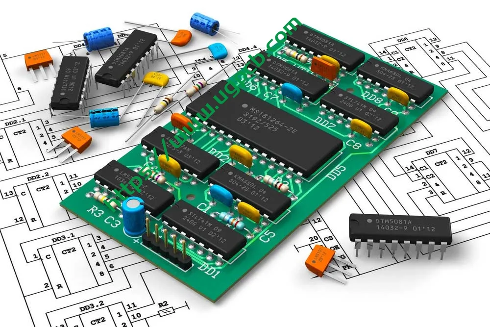
La PCB con orificio pasante de doble cara funciona con tres tecnologías principales:
1. Enrutamiento de doble cara — Los patrones de circuitos conductores están grabados en las superficies superior e inferior del sustrato aislante FR-4., permitiendo la colocación de componentes en ambos lados. Esto aumenta significativamente la densidad del circuito y la flexibilidad del diseño..
2. Orificio pasante chapado (PTH) Interconexión — Después de perforar, La deposición de cobre no electrolítico y el revestimiento de cobre electrolítico forman una capa conductora en las paredes del orificio.. Esto crea baja resistencia, conexiones eléctricas altamente confiables entre las capas superior e inferior. Según clase IPC-6012F 2, el espesor mínimo promedio de cobre recubierto en las paredes del orificio debe ser ≥ 20 μm.
3. Montaje y soldadura de componentes — Los componentes se montan a través del orificio. (Tht) o montaje en superficie (SMT) Técnicas y conectadas eléctricamente mediante soldadura por reflujo o por ola., produciendo una PCBA completamente funcional (Conjunto de placa de circuito impreso) módulo.
V. Clasificación de productos
Según el sistema de clasificación IPC-6012F para tableros impresos rígidos., El producto de UGPCB se clasifica de la siguiente manera:
| Dimensión de clasificación | Categoría |
|---|---|
| Por construcción | Tablero impreso rígido con orificios pasantes chapados, De dos caras (Tipo IPC-6012F 2) |
| Por clase de rendimiento | Clase 2 (Equipo electrónico de servicio dedicado) |
| Por material de sustrato | Laminado de tela de vidrio epoxi FR-4 (IPC-4101/21) |
| Por recuento de capas | 2-Tablero de capas |
| Por acabado superficial | HASL sin plomo |
| Por clasificación de inflamabilidad | UL 94 V-0 |
Por dominio de aplicación, este producto cae en el PCB de doble cara de grado industrial general categoría, adecuado para electrónica de consumo, controles industriales, equipo de comunicacion, adaptadores de corriente, y otras aplicaciones de confiabilidad media.
VI. Composición de materiales
6.1 Sustrato: laminado revestido de cobre FR-4
FR-4 es un laminado epoxi reforzado con vidrio compuesto de tejido de vidrio de calidad electrónica como refuerzo y resina epoxi como aglutinante., Consolidado bajo alta temperatura y presión.. Su UL 94 V-0 La clasificación de inflamabilidad significa que en la prueba de combustión vertical, el material se autoextingue dentro 10 segundos después de cada una de dos aplicaciones de llama de 10 segundos, sin gotas llameantes que enciendan el algodón.
6.2 Lámina de cobre — 1/1 ONZ
una onza (1 ONZ) de lámina de cobre tiene un espesor de 35 μm (1.37 mil). Usos de la UGPCB 1 Cobre OZ en ambas capas exteriores. (designado 1/1 ONZ), Garantizar la misma capacidad de transporte de corriente y conductividad en ambos lados..
6.3 Acabado de superficie: HASL sin plomo
HASL sin plomo implica sumergir la PCB en soldadura fundida sin plomo (típicamente Sn-Cu, Sn-Cu-Ni, o aleaciones Sn-Ag-Cu), luego use cuchillos de aire caliente de alta presión para nivelar y eliminar el exceso de soldadura. Esto produce un uniforme, Recubrimiento protector soldable en las superficies de cobre.. El proceso cumple con los requisitos IPC-6012F y las directivas medioambientales RoHS..
6.4 Máscara de soldadura y leyenda
-
Máscara de soldadura verde — Cubre todas las áreas del circuito excepto las almohadillas., proporcionando aislamiento, protección contra la oxidación, y prevención de cortocircuitos.
-
Leyenda serigrafiada blanca — Identifica designadores de referencia de componentes, marcadores de polaridad, números de pieza de la placa, y niveles de revisión para facilitar el montaje y la depuración.
VII. Rendimiento del producto
7.1 Rendimiento eléctrico
| Parámetro de rendimiento | Valor | Estándar de referencia |
|---|---|---|
| Constante dieléctrica (Dk) @ 1 GHz | 4.2–4,5 | IPC-4101 |
| Factor de disipación (df) @ 1 GHz | ≤ 0.020 | IPC-4101 |
| Resistencia de aislamiento | ≥ 10^12 Ω | IPC-6012F |
| Tensión soportada dieléctrica | Por rigidez dieléctrica | IPC-6012F |
7.2 Rendimiento mecánico
| Parámetro de rendimiento | Valor | Estándar de referencia |
|---|---|---|
| Grosor del tablero | 1.0 milímetros ± 10% | IPC-6012F |
| Resistencia al pelado de cobre | ≥ 1.1 N/mm | IPC-6012F |
| Calificación de inflamabilidad | UL 94 V-0 | Estándar UL |
| tg (Temperatura de transición vítrea) | 130–140°C | IPC-4101 |
7.3 Fiabilidad
Según clase IPC-6012F 2 requisitos, El producto debe pasar las siguientes verificaciones de confiabilidad.:
-
Prueba de tensión térmica (288°C, 10 artículos de segunda clase, sin delaminación ni ampollas)
-
Prueba de adhesión de cobre chapado en orificio pasante (espesor mínimo promedio de cobre de la pared del agujero ≥ 20 μm)
-
Prueba de soldabilidad
-
Prueba de continuidad eléctrica y resistencia de aislamiento
VIII. Estructura del producto
La PCB con orificio pasante de doble cara de UGPCB presenta una construcción simétrica de 2 capas. De arriba a abajo:
-
Capa de leyenda superior (Serigrafía blanca)
-
Capa de máscara de soldadura superior (tinta verde)
-
Capa superior de lámina de cobre (1 ONZ, 35 μm)
-
Sustrato aislante FR-4 (1.0 MM GRISIÓN)
-
Capa inferior de lámina de cobre (1 ONZ, 35 μm)
-
Capa de máscara de soldadura inferior (tinta verde)
-
Capa de leyenda inferior (Serigrafía blanca)
-
Orificios pasantes chapados (PTH) — Abarca todo el espesor del tablero con paredes perforadas recubiertas de cobre que permiten la interconexión entre capas
IX. Características del producto
-
Alta densidad de enrutamiento — El enrutamiento de doble cara ofrece entre un 60% y un 80% más de densidad que los tableros de una sola cara, compatible con diseños de circuitos más complejos.
-
Interconexión a través de orificios altamente confiable — Orificio pasante chapado (PTH) La tecnología garantiza la confiabilidad eléctrica a largo plazo entre capas., con espesor de cobre de pared de orificio que cumple con la clase IPC-6012F 2 requisitos (≥ 20 μm promedio).
-
Excelente retardo de llama — El sustrato FR-4 cumple con UL 94 V-0 calificación de inflamabilidad, Garantizar la seguridad en condiciones de funcionamiento anormales..
-
Sin plomo y respetuoso con el medio ambiente — El acabado superficial HASL sin plomo cumple con las directivas ambientales RoHS.
-
Capacidad de circuito de paso fino — Ancho de línea mínimo de 0.32 mm y separación mínima de 0.37 mm acomodar medio- a diseños de circuitos de alta densidad.
-
Estabilidad dimensional superior — Baja absorción de agua del FR-4 (≤ 0.10%) Garantiza un cambio dimensional mínimo en ambientes húmedos., preservando la precisión del montaje.
-
Proceso de fabricación maduro - Con 1.0 mm de espesor del tablero y 0.236 mm diámetro mínimo del agujero, la relación de aspecto de sólo 4.24:1 permite procesos maduros, altos rendimientos, y plazos de entrega cortos.
incógnita. Flujo del proceso de fabricación
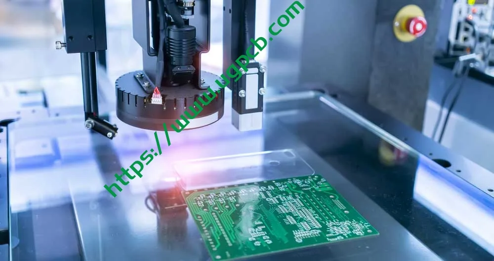
Proceso de fabricación de PCB con orificio pasante de doble cara estándar de UGPCB:
1. Inspección de material entrante → Verificar el espesor del laminado revestido de cobre FR-4, calidad de la lámina de cobre, y defectos visuales.
2. Corte → Corte el laminado revestido de cobre de gran formato al tamaño del panel de trabajo (86.9 × 73.58 milímetros).
3. Perforación → Utilice máquinas perforadoras CNC de alta precisión para perforar todos los orificios pasantes según la lima de perforación Gerber (diámetro mínimo 0.236 milímetros).
4. Orificio pasante chapado (PTH) → Deposite una fina capa de semilla de cobre en las paredes del pozo mediante deposición de cobre no electrolítica.
5. Revestimiento de paneles → Placa de cobre electrolíticamente para fortalecer la pared del orificio y la superficie del cobre hasta alcanzar el espesor objetivo. (1 ONZ).
6. Transferencia de patrones → Película seca laminada, exponer, y desarrollarse para formar el patrón de circuito resistente.
7. Aguafuerte → Grabe el cobre desprotegido para formar el patrón del circuito final..
8. Desnudándose → Retire la película seca resistente de las trazas del circuito..
9. Aplicación de máscara de soldadura → Aplicar tinta de máscara de soldadura verde, exponer, y desarrollar para exponer las almohadillas.
10. Acabado superficial → HASL sin plomo.
11. Impresión de leyendas → Leyenda serigrafiada blanca serigrafiada.
12. Enrutamiento / Corte en V → Enrutamiento CNC hasta el contorno final de la placa.
13. Prueba eléctrica → Prueba de sonda volante o dispositivo para verificar la integridad abierta/cortada.
14. Control de calidad final (FQC) → Inspección visual, muestreo dimensional, y embalaje para el envío.
XI. Escenarios de aplicación
Placas PCB FR-4 con orificio pasante de doble cara UGPCB, con su desempeño equilibrado y procesos maduros, son ampliamente utilizados en:
11.1 Electrónica de Consumo
-
Adaptadores de potencia y cargadores
-
Tableros de control de electrodomésticos
-
Dispositivos domésticos inteligentes
11.2 Controles industriales
-
Controladores lógicos programables PLC
-
Módulos de potencia industriales
-
Instrumentación y medidores.
11.3 Equipo de comunicación
-
Enrutadores y conmutadores
-
Módulos de comunicación
-
Dispositivos de conversión de señal.
11.4 Electrónica automotriz
-
Cargadores a bordo
-
Módulos de control de carrocería (no crítico para la seguridad)
-
Sistemas de infoentretenimiento
11.5 Dispositivos médicos
-
Placas auxiliares para monitor de paciente
-
Equipo médico portátil (Clase 2 aplicable)
XII. Guía de selección y ventajas del producto
12.1 ¿Por qué elegir PCB con orificio pasante de doble cara UGPCB??
-
Control de procesos compatible con IPC — Desde la selección de materiales hasta los productos terminados., Cumplimiento total de IPC-6012F, IPC-4101, y otras normas internacionales.
-
Fabricación de alta precisión — Diámetro mínimo del agujero de 0.236 mm y ancho de línea mínimo de 0.32 mm encuentro medio- a requisitos de diseño de alta densidad.
-
Cumplimiento ambiental — El acabado superficial HASL sin plomo cumple con RoHS 2.0 directivas.
-
Fiabilidad probada — El sustrato FR-4 ha sido validado en el mercado durante décadas con un rendimiento constante.
-
Entrega rápida — Las especificaciones estándar cuentan con amplias materias primas., garantizando plazos de entrega confiables.
12.2 Referencia de selección
Los PCB con orificio pasante de doble cara UGPCB son la opción ideal cuando su proyecto cumple con estos criterios:
-
Complejidad moderada del circuito que 2 las capas pueden acomodar
-
Frecuencia de funcionamiento inferior 1 GHz (FR-4 funciona excelentemente en este rango)
-
Entorno operativo a largo plazo que no exceda los 120°C
-
Aplicaciones sensibles a los costos que exigen un alto valor
XIII. Solicitar una cotización
UGPCB se compromete a ofrecer fabricación de PCB de alta calidad y servicios de PCBA llave en mano a clientes de todo el mundo.. Ya sea que necesite PCB con orificio pasante de doble cara con especificaciones estándar o requisitos personalizados (espesor de tablero especial, peso de cobre, acabado superficial, control de impedancia, etc.), El equipo de expertos de UGPCB brinda soporte total desde el diseño de ingeniería hasta la producción en volumen..
Obtenga una cotización hoy:
-
Enviar archivos Gerber + especificaciones: reciba una cotización dentro de 24 horas
-
Soporte desde el prototipo hasta la producción de gran volumen.
-
Diseño gratuito para fabricación (DFM) revisar
Contacto UGPCB:
📧 Consultas de ventas: [ventas@ugpcb.com]
🌐 Sitio web: [www.ugpcb.com]
XIV. Declaración de fuente de datos
Los estándares y datos citados en este documento provienen de las siguientes organizaciones autorizadas:
-
PCI (Asociación que conecta industrias electrónicas): IPC-6012F Especificación de calificación y rendimiento para tableros impresos rígidos (Septiembre 2023); IPC-4101 Especificación de Materiales Base para Tableros Impresos Rígidos y Multicapa; IPC-2221 Norma genérica sobre diseño de tableros impresos; IPC-7351 Requisitos genéricos para el diseño de montaje en superficie y el estándar de patrón de terreno
-
UL (Laboratorios aseguradores): UL 94 Norma para pruebas de inflamabilidad de materiales plásticos para piezas de dispositivos y electrodomésticos
-
NO (Asociación Nacional de Fabricantes Eléctricos): Definición de grado de material FR-4
-
Datos técnicos estándar de la industria: Constante dieléctrica FR-4, factor de disipación, y otros parámetros de propiedades materiales













