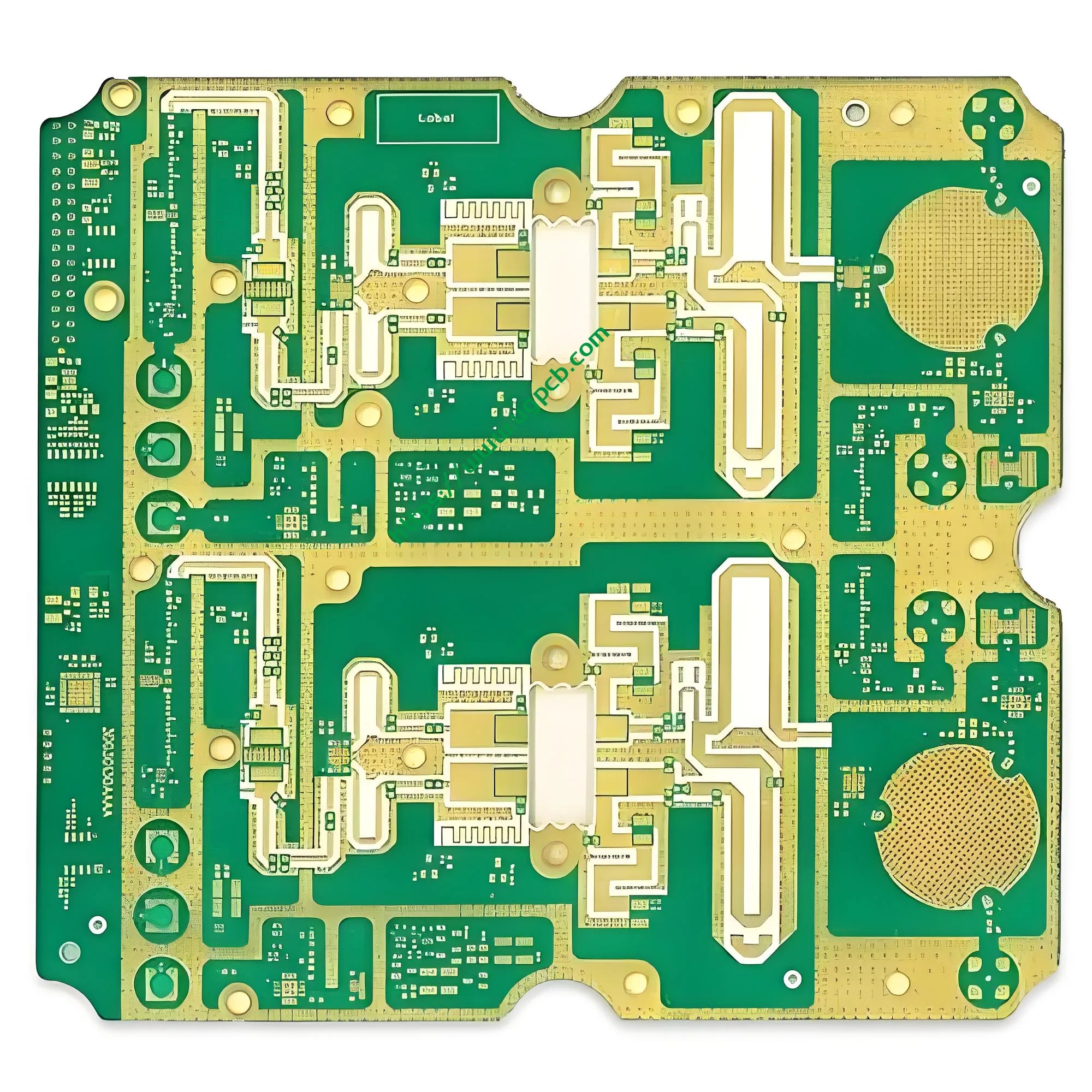
Descripción general del producto
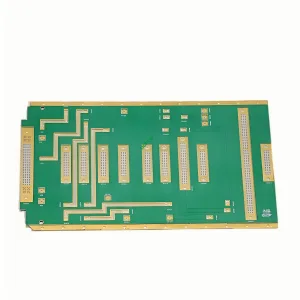
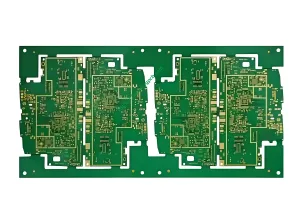
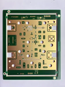
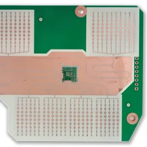
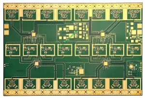
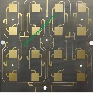
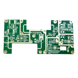
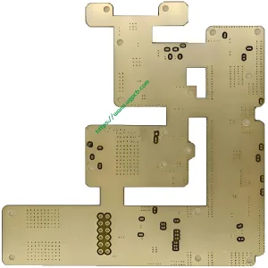
La placa PCB de Lightwave Communications es una persiana híbrida de 6 capas de alto rendimiento enterrada a través de una placa de circuito impreso diseñada por UGPCB para aplicaciones de comunicación óptica y transmisión de señales digitales de alta velocidad.. Este producto presenta una combinación híbridaMaterial digital de alta velocidad TU872 conMaterial de alta frecuencia Rogers RO4350B. El diseño combina capacidades de procesamiento de señales digitales de alta velocidad con un rendimiento excepcional de transmisión de señales de RF y microondas.. Esta PCB sirve como una solución de interconexión ideal para equipos receptores de tierra de comunicación óptica., transceptores ópticos de alta velocidad, y módulos frontales de RF de estación base.
El tarjeta de circuito impreso La industria continúa su impulso hacia frecuencias más altas., velocidades más rápidas, y mayor densidad. Las soluciones de un solo material ya no pueden satisfacer las demandas contradictorias de las señales digitales de alta velocidad y las señales analógicas de RF.. UGPCB aborda este desafío a través del diseño híbrido TU872+RO4350B. Esta PCB de 6 capas logra un equilibrio óptimo entre la integridad de la señal, gestión térmica, y costo de fabricación.

Clasificación de productos
Por IPC-6012EEspecificación de calificación y rendimiento para tableros impresos rígidos, este producto cae en las siguientes categorías:
| Dimensión de clasificación | Categoría |
|---|---|
| Tipo de estructura | Tablero impreso rígido multicapa (6 capas) con vias ciegas y enterradas |
| Sistema de materiales | Laminado híbrido (material digital de alta velocidad + material de alta frecuencia) |
| Acabado superficial | Níquel químico/oro de inmersión (ACEPTAR), para IPC-4552 |
| Clase de confiabilidad | Cumple con la clase IPC-6012 2 (productos electrónicos de servicio dedicado) y clase 3 (productos electrónicos de alta confiabilidad) requisitos |
| Calificación de inflamabilidad | UL 94 V-0 |
| Dominio de aplicación | comunicación óptica / PCB de infraestructura de telecomunicaciones |
Especificaciones técnicas básicas
| Parámetro | Especificación |
|---|---|
| capas | 6 capas |
| Material | TU872 (capas digitales de alta velocidad) + RO4350B (capas de alta frecuencia) |
| Grosor del tablero | 1.8 milímetros |
| Espesor de cobre | 35/35/35/35 μm (distribución uniforme en todas las capas) |
| Diámetro de agujero más pequeño | 0.20 milímetros |
| Tratamiento superficial | ACEPTAR (2Ud.” espesor de oro) |
| Características técnicas | Taponamiento al vacío + Vías ciegos y enterrados |
Propiedades clave de los materiales
Material de alta frecuencia Rogers RO4350B (para capas de señal de RF/microondas):
- Constante dieléctrica (Dk): 3.48 ± 0.05 @ 10 GHz
- Factor de disipación (df): 0.0037 @ 10 GHz
- Coeficiente de expansión térmica del eje Z (CTE): 32 ppm/°C
- Calificación de inflamabilidad: UL 94 V-0
- Conductividad térmica: 0.69 W/(m · k)
Material digital de alta velocidad TU872 (para capas de señales digitales de alta velocidad):
- Constante dieléctrica (Dk): < 3.5 @ 10 GHz
- Factor de disipación (df): ~0,009 @ 10 GHz
- Alta temperatura de transición vítrea (tg) con excelente estabilidad térmica y resistencia CAF
Pautas de diseño
Arquitectura de apilamiento híbrido
Esta PCB de 6 capas emplea una pila híbrida con materiales TU872 y RO4350B. Las posiciones centrales del principio de diseño.RO4350B en capas externas o capas de señal específicas que requieren transmisión de señal RF de alta frecuencia, mientrasTU872 sirve a las capas de procesamiento de señales digitales de alta velocidad. Esta asignación estratégica de material permite que una sola PCB maneje tanto señales de RF de nivel GHz como señales lógicas digitales de alta velocidad., Eliminando los compromisos de rendimiento inherentes a las soluciones de un solo material..
Ciego y enterrado vía diseño
Las vías ciegas conectan las capas exteriores con las interiores sin penetrar todo el espesor del tablero.. Las vías enterradas residen completamente dentro del tablero., invisible desde cualquier superficie exterior. Esta PCB de 6 capas aprovecha la tecnología de vía ciega y enterrada para lograr una densidad de enrutamiento de nivel HDI.
Por IPC-6012E, tablas de múltiples capas con vías ciegas y enterradas deben cumplir estrictos requisitos de revestimiento y relleno. El 0.20 El diámetro mínimo del orificio de mm equilibra el rendimiento de fabricación con la capacidad de enrutamiento de alta densidad.. En un tablero de 6 capas, Las vías ciegas desde la capa exterior a las capas interiores requieren un control de profundidad preciso: deben penetrar hasta la capa interior objetivo sin dañar los circuitos de la capa interior., manteniendo suficiente área de conexión.
Diseño de control de impedancia
La impedancia característica de las líneas de transmisión de señales sigue esta fórmula (estructura de microbanda):
Dónde es la constante dieléctrica, es el espesor dieléctrico, es el ancho de rastreo, y es el espesor del cobre. La estrecha tolerancia Dk del RO4350B de ±0,05 garantiza una desviación mínima entre los valores de impedancia diseñados y fabricados.. Esta precisión resulta fundamental para un control preciso de impedancia diferencial de 50 Ω de un solo extremo o de 100 Ω en equipos de comunicación óptica..
Principios operativos
Principios de transmisión de señales
En altas frecuencias, Las líneas de transmisión de señal de PCB funcionan comolíneas de transmisión de parámetros distribuidos. La constante dieléctrica (Dk) del material del sustrato determina la velocidad de propagación de la señal:
Dónde es la velocidad de la luz en el vacío (3×10⁸m/s) y es la constante dieléctrica efectiva. Valor Dk bajo del RO4350B (3.48) permite la propagación de la señal a aproximadamente 54% de la velocidad de la luz en el vacío, significativamente más rápido que los materiales FR-4 convencionales (Dk ≈ 4.2-4.8).
Mecanismos de pérdida
La pérdida total de señal en las líneas de transmisión de PCB consiste enpérdida del conductor ypérdida dieléctrica. La pérdida dieléctrica se correlaciona directamente con el factor de disipación del material. (df):
Dónde es la frecuencia de la señal y es df. Df del RO4350B de apenas 0.0037 en 10 GHz produce una pérdida dieléctrica extremadamente baja por unidad de longitud. Esta característica resulta esencial para las señales de comunicación óptica que funcionan a frecuencias superiores 10 GHz.
Ciego y enterrado mediante conexiones eléctricas
Las vías ciegas y enterradas establecen interconexiones verticales entre capas específicas dentro de la pila de PCB de 6 capas.. En comparación con las vías de orificio pasante, Reducen significativamente los efectos parásitos de capacitancia e inductancia que degradan la integridad de la señal de alta velocidad.. Esta reducción de los efectos parásitos tiene un impacto decisivo en el mantenimiento de la integridad de la señal para señales digitales y de RF de alta velocidad..
Proceso de fabricación
Preparación del laminado híbrido
La combinación híbrida TU872 y RO4350B representa el principal desafío de fabricación de este producto.. Estos dos materiales tienen diferentes características de CTE: el RO4350B exhibe un CTE en el eje Z de 32 ppm/°C, mientras que TU872 como sistema epoxi modificado tiene diferentes propiedades termomecánicas. UGPCB logra una unión y resistencia confiables de la interfaz híbrida mediante un control preciso de los parámetros de laminación (perfil de temperatura, perfil de presión, y tasa de rampa).
Ciego y enterrado mediante fabricación
- Enterrado a través de la formación: Los núcleos de la capa interna se someten a perforación y revestimiento de cobre antes de la laminación., encapsulando las vías enterradas dentro del tablero
- Ciego vía formación: Después de la laminación, La perforación de profundidad controlada desde la capa exterior apunta a la capa interior especificada con un control de profundidad preciso.
Proceso de taponamiento al vacío
Según la Guía de diseño IPC-4761 para la protección de tableros impresos a través de estructuras, La obturación por vacío se incluye en la protección Via Tipo VI. (llenar y cubrir completamente) o Tipo VII (relleno completo) categorias. Parámetros clave del proceso:
- Flujo de proceso: Perforación → Desmear →Taponamiento al vacío → Curado → Rectificado
- Tasa de llenado del enchufe: ≥ 85% (según los requisitos de IPC-6012)
- El ambiente de vacío elimina las burbujas de aire de los orificios de paso., asegurando el llenado completo de resina de vías ciegas y enterradas
Acabado superficial (ACEPTAR)
Níquel químico/oro de inmersión (ACEPTAR, 2Ud.” espesor de oro) El acabado superficial cumple con las especificaciones IPC-4552.:
- Capa de níquel no electrolítico: 3-6 μm
- Capa de oro de inmersión: ≥ 0.05 μm (2Ud.” ≈ 0.05 μm)
- ENIG proporciona una superficie soldable plana, excelente soldabilidad, y larga vida útil
Características de rendimiento
Integridad de señal (Y) Ventajas
- Baja pérdida de inserción: Bajo Df del RO4350B (0.0037@10 GHz) Minimiza la pérdida de energía de la señal de alta frecuencia durante la transmisión.
- Baja variación constante dieléctrica: La tolerancia Dk de sólo ±0,05 garantiza la consistencia de la impedancia
- Rendimiento eléctrico estable: TU872 mantiene las propiedades eléctricas en diferentes condiciones de temperatura y humedad.
Rendimiento de la gestión térmica
- 1.8 El espesor del tablero de mm proporciona una excelente masa térmica y resistencia mecánica.
- Conductividad térmica RO4350B de 0.69 W/(m · k) disipa eficazmente el calor
- La alta Tg del TU872 garantiza la estabilidad dimensional a temperaturas elevadas
Fiabilidad
- El taponamiento por vacío garantiza vías ciegas y enterradas sin huecos, Cumpliendo con la Clase IPC-6012 2/3 requisitos
- Uniforme 35 El espesor de cobre de μm en las cuatro capas garantiza la capacidad de transporte de corriente y la disipación de calor.
- UL 94 V-0 clasificación de inflamabilidad: la llama se extingue dentro 10 segundos después de la eliminación
Escenarios de aplicación
Equipo receptor terrestre
Esto representa elaplicación de destino principal para este producto. Los equipos receptores terrestres deben procesar simultáneamente señales de RF de alta frecuencia procedentes de satélites o enlaces de microondas. (Requiere material RO4350B) y procesamiento de señales digitales de banda base (Requiere material TU872). Este de 6 capas PCB híbrido aborda precisamente este doble requisito.

Sistemas de comunicación óptica
- Equipos de transmisión de red de fibra óptica.
- Transceptores ópticos
- amplificadores ópticos
Comunicaciones digitales de alta velocidad
- 5Terminales frontales de RF de la estación base de comunicación G
- Equipos de conmutación de datos de alta velocidad.
- Instrumentos de prueba y medida.
Por qué elegir UGPCB?
- Tecnología de laminación híbrida madura: Amplia experiencia en producción con apilados híbridos TU872+RO4350B con rendimiento controlable
- Capacidad avanzada de vía ciega y enterrada: 0.20 El diámetro mínimo del orificio de mm con taponamiento al vacío cumple con los requisitos de interconexión HDI.
- Control de calidad de extremo a extremo: Gestión de calidad de proceso completo desde la recepción del material hasta el envío del producto terminado., estrictamente según los estándares IPC-6012E
- Respuesta Rápida: El equipo de ingeniería profesional proporciona DFM (Diseño para la fabricación) soporte de revisión
Guía de consulta
Para obtener muestras, precios por volumen, o soporte técnico para la placa PCB de comunicaciones Lightwave, por favor proporcione:
- Archivos Gerber (incluyendo detalles de acumulación)
- lista de materiales (si se requieren servicios de PCBA)
- Requisitos especiales de rendimiento (valores de impedancia, especificaciones de prueba, etc.)
El equipo de UGPCB entregará una evaluación técnica profesional y una cotización dentro de 24 horas.
Declaración de fuente de datos
Los datos técnicos y las normas citadas en este documento provienen de las siguientes fuentes autorizadas.:
- Corporación Rogers – Hoja de datos del laminado RO4350B™
- PCI (Asociación que conecta industrias electrónicas) – IPC-6012E Especificación de calificación y rendimiento para tableros impresos rígidos; IPC-4761 Guía de diseño para la protección de tablero impreso mediante estructuras; IPC-4552 Especificación de rendimiento para níquel químico/oro por inmersión (ACEPTAR) Revestimiento para tableros impresos
- UL (Laboratorios aseguradores) – UL 94 Norma para pruebas de inflamabilidad de materiales plásticos para piezas de dispositivos y electrodomésticos
- Tecnología Taiyo (TUC) – Datos técnicos del material de alta velocidad TU-872 SLK