

FPC (フレキシブルプリント基板) is changing modern electronics design. According to BCC Research, the global FPC market will grow from 23.3billionin2025to41.7 10億 2030. That is a CAGR of 12.3%. Research and Markets data shows the 2025 market at 28.36十億,risingto31.07 10億インチ 2026 (CAGR 9.5%). Three main drivers fuel this growth: lightweight consumer electronics, EV adoption, および5Gインフラストラクチャ. High-performance FPC is now the fastest-growing segment in the プリント基板 業界.
UGPCB is a professional PCB/PCBA manufacturer. We offer one-stop custom FPC services from design to mass production. This page covers our FPC product specifications, 技術的なパラメーター, classification standards, and key advantages. You will find the best soft board solution for your project.
What Is an FPC Flexible Circuit Board? – Product Overview
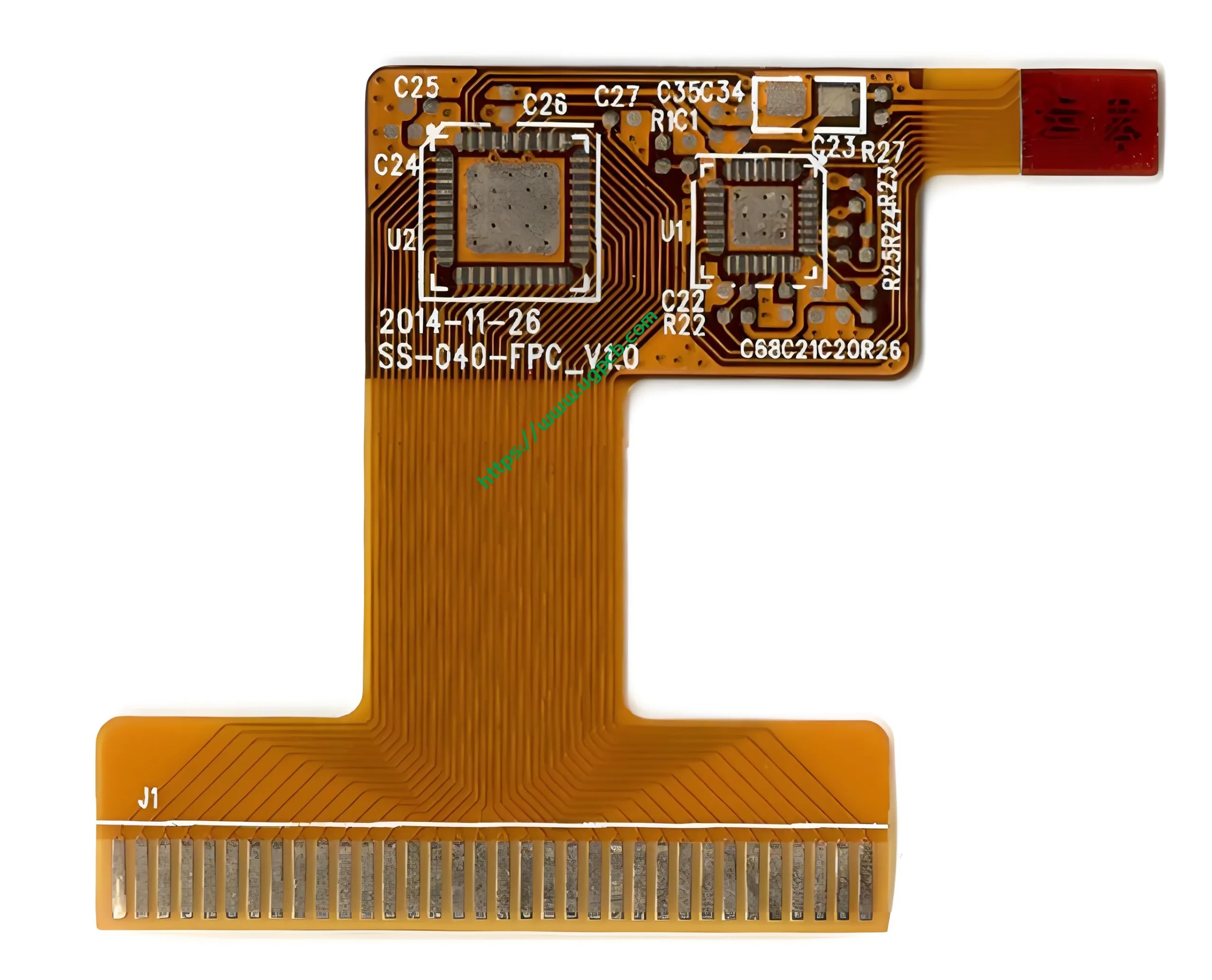
FPC stands for Flexible Printed Circuit Board. It is also called a flex board or flexible circuit. The insulation base material is polyimide (PI) or polyester (ペット). A precise etching process forms conductive traces on this thin flexible substrate. Unlike a rigid プリント基板, an FPC can bend, fold, and twist in 3D space. This flexibility perfectly supports modern trends toward smaller, lighter, and more integrated electronics.
IPC-6013E-2021 defines flexible printed boards as single-sided, 両面, 多層, or rigid-flex multilayer structures. These may include stiffeners, plated through holes (PTH), and blind/buried vias. UGPCB strictly follows IPC-2221 design standards and IPC-6013 performance specifications. Every FPC we produce meets international industry requirements.
UGPCB FPC Technical Parameters at a Glance
| パラメーター | UGPCB FPC Range | メモ / Reference |
|---|---|---|
| レイヤー数 | 1 - 12 レイヤー | Multilayer FPC holds 39.4% global share (BCC Research, 2026) |
| Base material | PI (ポリイミド), ペット (ポリエステル) | High-temp PI is top choice for high-end FPC |
| 仕上げた厚さ | 0.1mm – 0.8mm | Ultra-thin design suits wearables |
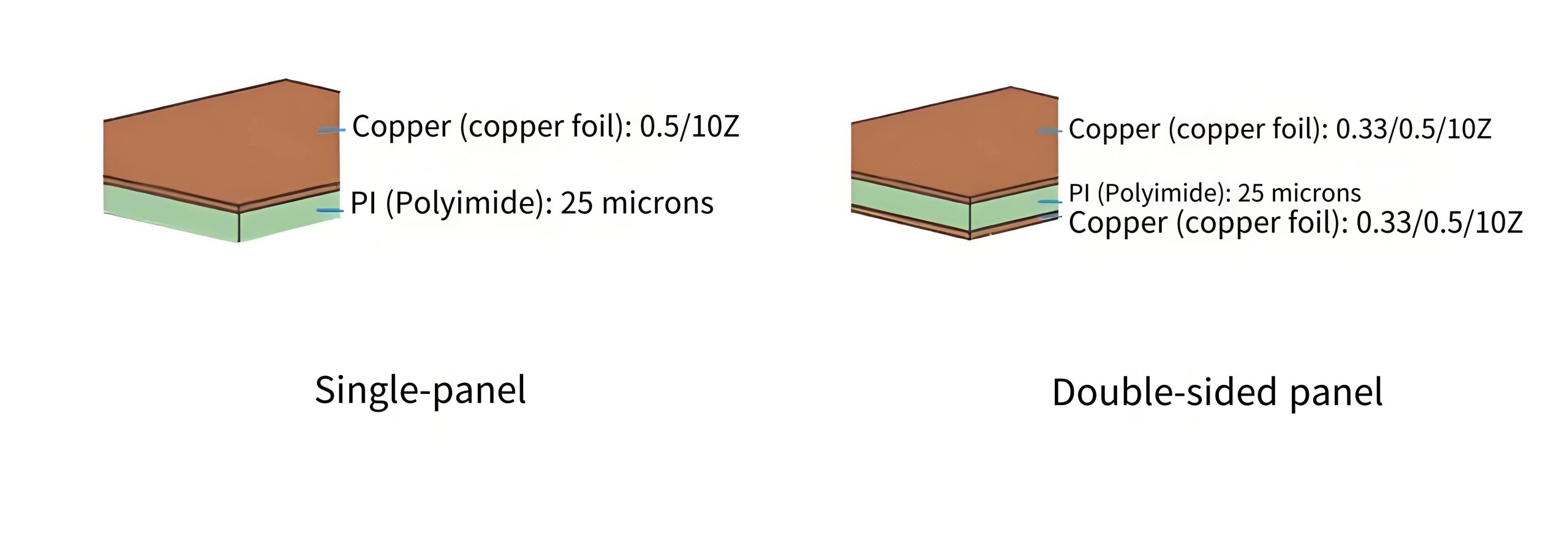
| 銅の厚さ | 1/3 oz – 1 オンス (≈12µm – 35µm) | 片面: 18µm/35µm; 両面: 12µm/18µm/35µm |
| ソルダーマスクの色 | 黄色 / 緑 / 白 | Yellow for general; black for high-end/anti-glare; white for reflective needs |
| 表面仕上げ | 同意する / OSP | ENIG for fine pitch & Al wire bonding; OSP for lead-free soldering |
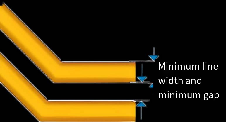
| Min trace/space | 2ミル/2ミル (≈0.05mm/0.05mm) | Extreme capability; 3/3mil recommended for lower cost |
| Min hole diameter | 0.1mm (≈4mil) | サポート HDIデザイン |
Product Classification Based on IPC-6013
IPC-6013 defines three classification dimensions.
By Type (層 & 構造)
| タイプ | 意味 | UGPCB Support |
|---|---|---|
| タイプ 1: Single-sided FPC | One conductive layer, with or without stiffener | ✓ |
| タイプ 2: Double-sided FPC | Two conductive layers with PTH, with or without stiffener | ✓ |
| タイプ 3: Multilayer FPC | Three or more conductive layers with PTH, with or without stiffener | ✓ (まで 12 レイヤー) |
| タイプ 4: Rigid-flex | Combination of rigid and flexible layers, three or more conductive layers with PTH | ✓ |
| タイプ 5: Flex/rigid-flex without PTH | Two or more conductive layers, no PTH | ✓ |
By Performance Class (Use Scenario) – IPC-6011 & IPC-6013
-
クラス 1 – General electronic products. Minimum reliability requirement for consumer electronics. Least strict testing.
-
クラス 2 – Dedicated service electronics. Higher performance for communication and industrial control equipment.
-
クラス 3 – High-performance electronics. Strict reliability for medical, 航空宇宙, and military applications.
By Flexing Condition (Installation & 使用)
-
Use A – Withstands single bending during installation.
-
Use B – Withstands specified repeated flex cycles.
-
Use C – Suitable for high-temperature environments above 105°C (221°F).
-
Use D – UL certified (meets UL 94 and UL 796F).
Applications of FPC Flexible Circuit Boards
FPC’s thin and flexible nature enables wide use in:
-
家電 – Smartphones (画面, camera, battery connections), 錠剤, ラップトップ, スマートウォッチ, TWS earbuds, ドローン.
-
自動車電子機器 – In-vehicle displays, カメラモジュール, センサー, バッテリー管理システム (BMS), アダス, LEDライト.
-
医療機器 – Portable monitors, 補聴器, endoscopes, wearable health trackers, implantable devices.
-
産業用制御 – Robot joints, precision instruments, internal wiring harnesses, IoT terminals.
-
航空宇宙 & 防衛 – Lightweight interconnects for satellites, missiles, レーダーシステム.
-
5G telecom – Base station antennas, RFフロントエンドモジュール, high-speed signal lines.
BCC Research notes that multilayer FPCs hold 39.4% 世界市場の. This share keeps growing because smartphones, ウェアラブル, 自動車エレクトロニクス, and medical devices demand higher circuit density.
FPC Base Materials and Performance Features
Primary Base Materials
-
PI (ポリイミド) – Excellent high-temperature resistance (-40°C〜 +125°C) and dimensional stability. Top choice for high-end FPC.
-
ペット (ポリエステル) – Lower cost. Suitable for consumer applications without extreme temperature requirements.
Top industry suppliers use adhesiveless materials from Panasonic and DuPont, plus adhesive-based materials and coverlays from Sunky.
主なパフォーマンス機能
| 特徴 | UGPCB FPC Advantage |
|---|---|
| 柔軟性 | Supports Use A (single bend) and Use B (repeated flex). Bending radius ≥1.2× board thickness gives over 300,000 flex cycles. |
| 薄い & ライト | Finished thickness as low as 0.1mm – saves internal device space. |
| Temperature resistance | PI-based FPC works from -40°C to +125°C. |
| Flex life | Optimized design and material choice achieve 300,000+ repeated bends. |
| 高密度相互接続 | 1.5mil/1.5mil trace/space and 0.1mm min hole meet high integration needs. |
Design Guidelines and Working Principle
How an FPC Works
An FPC works like a rigid プリント基板: copper traces on an insulating substrate provide electrical connections between components. The difference is the flexible substrate (PI/PET). This allows the board to bend in 3D space, enabling complex and compact interconnects inside tight product enclosures.
Key Design Points per IPC-2221
-
Conductor spacing & クリアランス – Determine minimum safe distance based on working voltage. For 1kV DC/AC peak, 汚染度 2, uncoated environment, IPC-2221 recommends clearance ≥2.0mm.
-
Minimum trace/space – UGPCB supports 1.5mil/1.5mil. We suggest 3/3mil or above to lower manufacturing difficulty and cost.
-
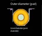
Via design – Outer diameter should be at least 0.2mm larger than inner diameter (≥0.25mm recommended). A practical balance: 0.3mm inner, 0.55mm outer.
-
インピーダンス制御 – For high-frequency signals, we offer controlled impedance within ±10% tolerance.
-
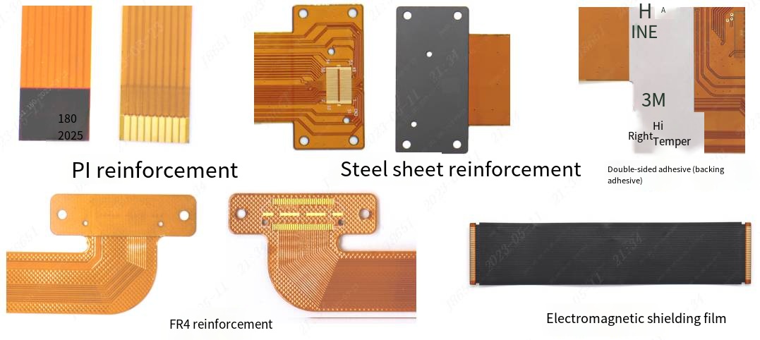
補強材の設計 – Add stiffeners at component mounting areas or ZIF connector interfaces. Common materials: PI, FR4, steel.
-
Bending area design – Avoid vias and pads in repeated bend zones. Route traces at 90° or with arcs. Place the bend centerline on copper-free areas to maximize flex life.
生産の流れの概要
UGPCB follows IPC-6013 performance specifications through these key steps:
-
Material cutting – Cut PI/PET base material to size.
-
掘削 – Mechanical or レーザー穴あけ. Minimum hole diameter 0.1mm.
-
Electroless copper / メッキ – Deposit conductive copper on hole walls to form PTH.
-
Circuit patterning – Laminate dry film → expose → develop → etch → strip film to create fine circuits.
-
Coverlay lamination – Apply coverlay as solder mask protection.
-
Stiffener attachment – Bond PI, FR4, or steel stiffeners on reinforced areas.
-
表面仕上げ – ENIG (エレクトロレスニッケルイマージョンゴールド) or OSP.
-
Outer contour – Die punching or laser cutting.
-
Electrical test – Continuity and impedance tests (deviation ≤ ±8%).
-
FQC & 梱包 - あおい, dimensional inspection, and final packing.
Why Choose UGPCB for FPC Flexible Circuit Boards?
1. Full specification custom solutions – Support 1 に 24 レイヤー, PI/PET base materials, multiple surface finishes, and solder mask colors. Meets your unique design needs.
2. Industry-leading precision – 1.5mil/1.5mil trace/space, 0.1mm min hole diameter, and 0.1mm finished thickness. Enables high-density interconnect designs.
3. Strict IPC compliance – All FPC products follow IPC-2221 design standards and IPC-6013 performance specifications. Quality guaranteed.
4. One-stop PCBA assembly service – UGPCB not only manufactures high-quality bare FPCs but also provides complete PCBAアセンブリ. We handle component sourcing, SMT placement, and finished product testing. This streamlines your supply chain from プリント基板 に プリント基板, saving communication costs and shortening time to market. Contact our technical sales engineers for more PCBA service details.
5. Fast response and flexible support – Whether you need prototyping or mass production, we put your needs first. Expect professional, 効率的, and reliable custom FPC service.
How to Get a Quote?
UGPCB aims to be your trusted FPC partner. To request a quote or technical consultation, please contact us with:
-
Your design files – Gerber files, design specification, or BOM list.
-
重要なパラメーター – Layer count, base material type, 仕上がり厚さ, copper weight, 表面仕上げ, min trace/space, min hole diameter.
-
Quantity and lead time – Sample quantity, mass production volume, and expected delivery date.
Our technical engineers will provide a professional DFM analysis and accurate quote within 24 時間.
👉 Request a quote today and start your custom FPC journey!
Data References
Key data in this document comes from:
-
✅ IPC-6013E-2021 – Qualification and Performance Specification for Flexible and Rigid-Flex Printed Boards
-
✅ IPC-2221 – Generic Standard on Printed Board Design
-
✅ BCC Research (2026) - Global Flexible PCB Market Report
-
✅ Research and Markets (2026) - Flexible Printed Circuit Board Market Report
-
✅ Industry standard FPC technical specifications (based on JLCPCB FPC parameters)
Contact us for fast FPC quotes and professional support.
© UGPCB. 無断転載を禁じます.


