
1. Automotive Instrument PCB Visão geral
Our Automotive Instrument PCB is a high-performance placa de circuito impresso engineered specifically for the rigorous demands of vehicle dashboard systems, including instrument clusters and display units. Designed with reliability and precision at its core, this PCB ensures stable operation of critical gauges, warning lights, and digital readouts that drivers depend on every day. No UGPCB, we specialize in manufacturing PCBs that meet the stringent quality and durability standards of the automotive industry, making us your trusted partner for automotive PCB and PCBA soluções.

2. What is an Automotive Instrument PCB?
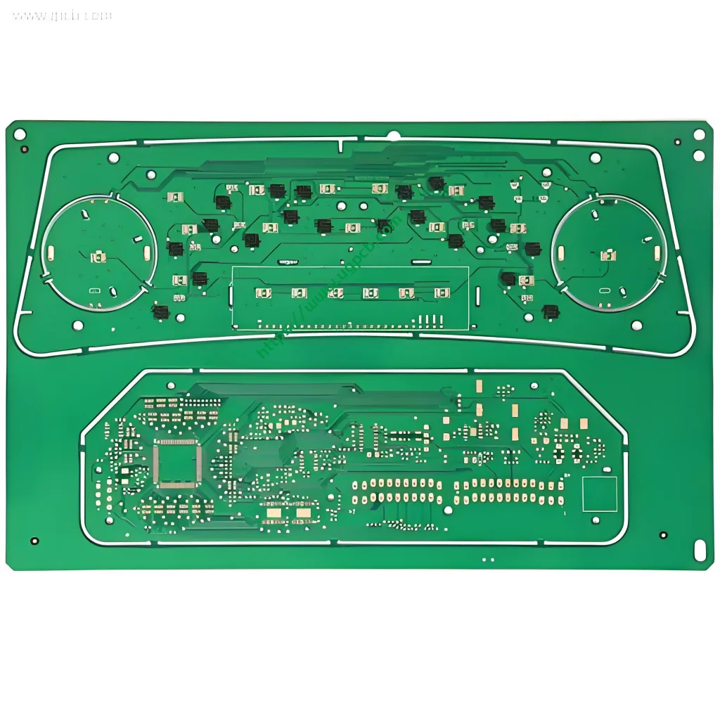
An Automotive Instrument PCB is the central nervous system of a vehicle’s instrument panel. It is a specialized printed circuit board that interconnects and provides a stable platform for electronic components like microcontrollers, sensores, LED indicators, and display drivers. This PCB is responsible for processing data from various vehicle sensors and accurately presenting information such as speed, engine RPM, fuel level, and engine temperature to the driver. The reliability of this PCB is paramount for vehicle safety and functionality, underscoring the importance of high-quality Fabricação de placas de circuito impresso e PCBA assembly services.
3. Design Key Points
The design of this PCB prioritizes signal integrity, Gerenciamento térmico, e confiabilidade de longo prazo em ambientes severos.
-
Seleção de material: The use of S1000-2 TG170 FR4 material provides a high glass transition temperature (Tg), essential for withstanding the elevated temperatures found in automotive cabins.
-
Traço e espaço: With a minimum trace width and spacing of 6mil (0.15milímetros), the design supports a dense layout of circuits, allowing for a compact and feature-rich instrument panel.
-
Espessura do Cobre: A standard 1oz copper thickness ensures good current-carrying capacity and manufacturability.
-
Acabamento superficial: The Organic Solderability Preservative (OSP) surface treatment offers a flat, planar surface ideal for fine-pitch components and provides excellent solderability for the Montagem PCBA processo.
4. How It Works
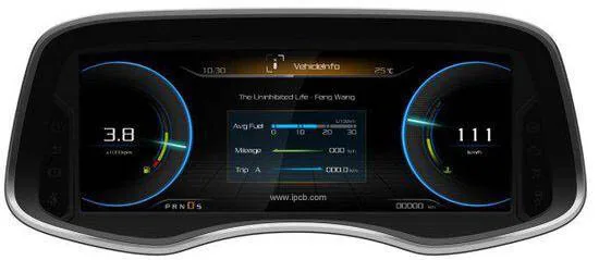
The Automotive Instrument PCB functions as an information hub. Electrical signals from vehicle sensors (por exemplo, vehicle speed sensor, coolant temperature sensor) are transmitted to the PCB. Integrated circuits on the board, such as a microcontroller, process these signals. The PCB then routes the processed data to the appropriate output devices—stepper motors for analog gauges, LED drivers for warning lights, or digital interfaces for LCD/LED screens—resulting in the real-time display of vehicle metrics to the driver.
5. Primary Applications and Uses
This PCB is specifically designed for eletrônica automotiva, with its primary use in:
-
Instrument Clusters (Analog and Digital)
-
Central Information Displays
-
Warning and Indicator Light Panels
-
Heads-Up Display (HUD) Control Units
-
Telematics Control Units
6. Classificação
Printed circuit boards can be classified in several ways. This specific product falls into the following categories:
-
Por contagem de camadas: A 2-layer PCB, offering a robust and cost-effective solution for many automotive instrument applications.
-
By Material Type: A High-Tg FR4 PCB, indicating its enhanced thermal reliability.
-
Por aplicação: A dedicated automotive PCB, designed to meet industry-specific standards like IPC-6012 and AEC-Q100 for components.
7. Materiais utilizados
The core material is critical to the PCB’s performance.
-
Material base: S1000-2 TG170 FR4. This denotes a halogen-free laminate with a Glass Transition Temperature (Tg) of 170°C. The high Tg value ensures the board’s mechanical stability is maintained under high thermal stress, preventing delamination or warping, which is crucial for the long-term reliability of automotive PCBA products.
8. Key Performance Attributes
This PCB is built to deliver consistent performance:
-
High Thermal Endurance: The TG170 material ensures stable performance in high-temperature environments.
-
Excelente integridade do sinal: Precise control over trace width and spacing minimizes signal loss and crosstalk.
-
Long-Term Reliability: The OSP finish and high-quality base material provide robust resistance against environmental factors, ensuring a long operational lifespan.
-
Força mecânica: A finished thickness of 1.2mm offers a rigid and durable structure that can withstand vibration and shock common in vehicles.
9. Physical Structure
The structure of this 2-layer Automotive Instrument PCB is defined by its key parameters:
-
Contagem de camadas: 2 Camadas
-
Espessura Acabada: 1.2milímetros
-
Espessura do Cobre: 1onças (approximately 35µm) on each layer
-
Cor da máscara de solda: Green or White (commonly used for high contrast and readability)
-
Acabamento superficial: OSP (Conservador de solda orgânica)
10. Características distintas & Benefícios
-
Automotive-Grade Reliability: Engineered with materials and processes that meet the high standards of the automotive industry.
-
Optimized for Assembly: The OSP surface and controlled impedance design facilitate a smooth and high-yield Montagem PCBA processo.
-
Thermal Robustness: The high Tg FR4 material prevents failure under thermal cycling, a common challenge in automotive PCB applications.
-
Compact Design Capability: Fine line technology (6MIL Trace/Space) allows for miniaturization of the instrument cluster.
11. Visão geral do processo de produção
 Our production follows a stringent, IPC-compliant workflow to ensure quality:
-
Preparação de Materiais & Perfuração: The TG170 FR4 laminate is cut and drilled to create vias and mounting holes.
-
Patterning & Gravura: A photolithography process defines the circuit pattern, and unwanted copper is etched away to form precise traces.
-
Laminação & Curing: (For multi-layer boards; this 2-layer board undergoes a simpler process of solder mask application).
-
Aplicação de máscara de solda: The green or white solder mask is applied to protect the copper traces and define solderable areas.
-
Acabamento superficial: The OSP coating is applied to protect the copper pads from oxidation and ensure solderability.
-
Impressão de seda: Component designators and logos are printed.
-
Teste elétrico & Inspeção Final: Each board undergoes automated optical inspection (AOI) and electrical testing to verify continuity and isolation, guaranteeing a defect-free automotive instrument PCB.
12. Typical Usage Scenarios
This PCB is ideally deployed in the heart of a vehicle’s dashboard. It is mounted directly behind the instrument cluster faceplate, interfacing with the following:
-
Stepper Motors that control the needles of analog speedometers and tachometers.
-
LED and LCD Displays that show odometer readings, trip computer data, and gear position.
-
Warning Light Bulbs or LEDs for indicators like check engine, oil pressure, and battery alerts.
-
Connector Sockets that link the cluster to the vehicle’s main wiring harness.


