

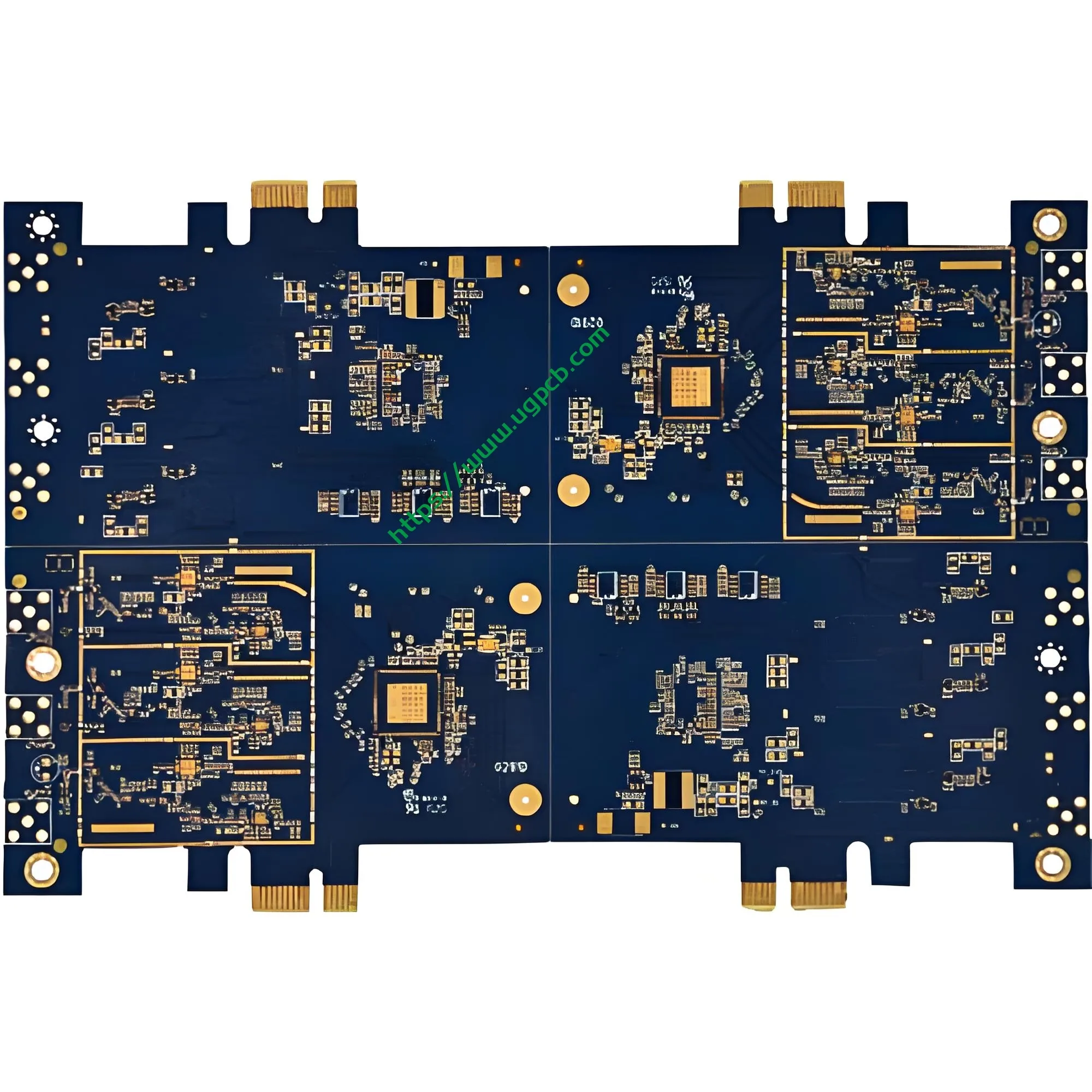
Visão geral do produto: O que é uma PCB de disco rígido mecânico de computador?
Um disco rígido mecânico de computador PCB (Placa de circuito impresso) é o componente de controle elétrico mais crítico dentro de uma unidade de disco rígido (Disco rígido). Esta placa carrega o chip controlador principal, memória cache, circuitos de gerenciamento de energia, e vários conectores de interface. Ele coordena as operações de leitura/gravação do cabeçote, controle do motor do fuso, e comunicação de dados entre o host e a mídia de armazenamento.
UGPCB apresenta estePCB de disco rígido mecânico de computador fabricado com padrão da indústria Material de fibra de vidro FR4. A placa mede 1,6 mm de espessura com dupla face (2-camada) projeto. Suas dimensões precisas são 53.68 x 42,7 mm, adaptado especificamente para dispositivos de armazenamento de disco rígido mecânico de 3,5 polegadas. Como o “centro neural” do disco rígido, a qualidade e o desempenho deste PCB determinam diretamente as taxas de transferência de dados, estabilidade de leitura/gravação, e vida útil geral.
No mundo atual orientado por dados, discos rígidos mecânicos mantêm uma posição insubstituível em data centers, computadores pessoais, vigilância de segurança, e armazenamento em nuvem devido à sua grande capacidade e baixo custo por gigabyte. Como o componente principal dos HDDs, oplaca de circuito do disco rígido exige qualidade e confiabilidade excepcionais.
Definição do Produto e Classificação Científica
Definição do Produto
UMPCB de disco rígido mecânico de computador é uma placa de circuito impresso rígida projetada especificamente para uso interno em unidades de disco rígido mecânicas (Disco rígido). Ele carrega o controlador principal, memória cache, circuitos de gerenciamento de energia, e conectores de interface para permitir o controle de leitura/gravação de dados, acionamento motorizado, e comunicação com o anfitrião.
Classificação Científica
Por IPC-6012FEspecificação de qualificação e desempenho para placas impressas rígidas, este produto se enquadra nas seguintes categorias de classificação científica:
| Dimensão de Classificação | Categoria |
|---|---|
| Por estrutura | Placa impressa dupla face rígida |
| Por contagem de camadas | 2-Placa de camada (2eu) |
| Por tipo de via | Com furos revestidos (PTH) |
| Por substrato | Fibra de vidro epóxi FR4 |
| Por classificação de inflamabilidade | UL 94 V-0 (Classificação mais alta de retardante de chama) |
| Por acabamento superficial | Chapeamento de ouro |
| Por classe de desempenho IPC | Aula 2 (Produtos eletrônicos de serviço dedicado) |
Por IPC-6012F, este produto é umPlaca impressa dupla-face rígida com furos revestidos. Atende à classe IPC 2 requisitos para equipamentos eletrônicos de serviço dedicado, garantindo confiabilidade sob operação contínua do HDD, variações de temperatura, e interferência eletromagnética.
Especificações de projeto e parâmetros técnicos
Material de substrato: Fibra de vidro FR4
Este produto usa FR4 (Retardador de chama 4) como material base, o laminado rígido mais utilizado na indústria de PCB. FR4 consiste em um aglutinante de resina epóxi reforçado com tecido de fibra de vidro. As principais vantagens incluem:
- Resistência mecânica superior: O reforço de fibra de vidro proporciona excelente resistência à flexão e estabilidade dimensional
- Excelente isolamento elétrico: Resistividade de alto volume e constante dielétrica estável
- UL 94 V-0 Classificação inflamabilidade: A chama se autoextingue dentro 10 segundos após a remoção da chama sem gotejamento
- Excelente resistência térmica: TG (temperatura de transição vítrea) ≥135°C, compatível com processos de soldagem sem chumbo
Espessura da placa e contagem de camadas: 1.6mm Design frente e verso
Espessura da placa: 1.6milímetros – Isso representa o “espessura dourada” na indústria de PCB e a especificação mais comum para placas rígidas de dupla face de acordo com IPC-6012. A espessura de 1,6 mm alcança um equilíbrio ideal entre resistência mecânica, resistência à flexão, e custo de fabricação.
Por IPC-6012F, a tolerância de espessura da placa acabada para uma espessura nominal de 1,6 mm é± 10%, produzindo uma faixa aceitável de1.44mm a 1,76 mm.
Contagem de camadas: 2 camadas (2eu) – O design de dupla face satisfaz os requisitos de complexidade de roteamento dos circuitos de disco rígido, ao mesmo tempo que alcança um equilíbrio ideal entre custo e desempenho. As camadas superior e inferior carregam traços, com furos banhados (PTH) fornecendo conexões elétricas intercamadas.
Especificações dimensionais precisas
Dimensões do contorno: 53.68 x 42,7 mm
UGPCB personaliza com precisão essas dimensões com base nos principais padrões da indústria de discos rígidos mecânicos de 3,5 polegadas, garantindo compatibilidade física com o gabinete do disco, motor de fuso, e conjunto do braço do atuador. O comprimento de 53,68 mm e a largura de 42,7 mm utilizam totalmente o espaço interno limitado do disco rígido enquanto maximizam a área funcional do circuito.
Parâmetros de roteamento de precisão
Diâmetro mínimo do orifício: 0.22milímetros
O diâmetro mínimo do furo de 0,22 mm representa um requisito de precisão de perfuração mecânica relativamente alto. A proporção (espessura da placa em relação ao diâmetro do furo) é1.6 / 0.22 ≈ 7.27:1, bem dentro do limite superior de perfuração mecânica convencional de ≤8:1. Isso garante espessura uniforme do revestimento de cobre e confiabilidade nas paredes dos furos.
Largura da linha / espaçamento entre linhas: 0.37 x 0,42 mm
O roteamento preciso com largura de linha de 0,37 mm e espaçamento entre linhas de 0,42 mm garante a integridade do sinal, ao mesmo tempo que fornece espaço de roteamento suficiente para barramentos de dados de alta velocidade. Esta combinação de parâmetros alcança um equilíbrio ideal entre rendimento de fabricação e desempenho elétrico.
Espessura da folha de cobre: 35/35μm (1 onças)
As folhas de cobre da camada superior e inferior medem35μm (1 onças) , representando a espessura típica de cobre do condutor externo para placas impressas rígidas de acordo com IPC-6012F.
Por IPC-D-275, a capacidade de transporte de corrente do condutor externo é calculada da seguinte forma:
eu = 0.0647 × (ΔT)^0,4281× (UM)^0,6734
Onde:
- I = Capacidade máxima de transporte de corrente (UM)
- ΔT = Aumento de temperatura permitido (°C)
- A = Área da seção transversal do condutor (mm²)
Para folha de cobre de 35 μm com largura de linha de 1 mm, a área da seção transversal do condutor A = 0,035 mm². Com um aumento de temperatura de 10°C, este condutor pode transportar aproximadamente1.0UM.
Com uma largura de linha de 0,37 mm, a capacidade de transporte de corrente correspondente é aproximadamente0.37UM (com aumento de temperatura de 10°C), atendendo totalmente aos requisitos atuais de linhas de sinal e energia em circuitos de disco rígido.
Acabamento superficial: Chapeamento de ouro
Este produto utilizaChapeamento de ouro como o acabamento superficial, com uma camada de níquel (2-3μm) depositado primeiro, seguido por uma camada dourada (≥0,025μm) nas superfícies das almofadas.
Principais vantagens do folheado a ouro:
- Excepcional resistência ao desgaste: A camada dura de ouro resiste a repetidos ciclos de acasalamento
- Resistência de contato extremamente baixa: Garante transmissão de sinal estável e confiável
- Excelente soldabilidade: A superfície dourada resiste à oxidação, permitindo alta confiabilidade de soldagem
- Estabilidade de armazenamento a longo prazo: A camada de ouro protege eficazmente as superfícies de cobre contra oxidação e corrosão
A camada de níquel serve como uma barreira de difusão, evitando a interdifusão entre cobre e ouro e evitando a formação de compostos intermetálicos frágeis de cobre-ouro, garantindo fundamentalmente a confiabilidade a longo prazo.
Máscara de solda e legenda: Máscara Azul com Personagens Brancos
Cor da máscara de solda: Azul
A máscara de solda azul fornece identificação visual distinta, ao mesmo tempo que oferece excelente proteção de isolamento e resistência à umidade. A máscara de solda cobre todas as áreas de roteamento, exceto pads, evitando efetivamente pontes de solda e curtos-circuitos durante a montagem.
Cor da legenda: Branco
A impressão da legenda branca na máscara de solda azul cria alto contraste. Designadores de referência de componentes, marcas de polaridade, e as informações da versão permanecem claramente legíveis, facilitando muito a colocação de SMT e subsequente inspeção e reparo.
Princípio Operacional: Como funciona o armazenamento de dados da unidade HDD PCB?
A PCB do disco rígido mecânico do computador opera nos seguintes níveis:
Decodificação e execução de comandos
Quando o computador envia comandos de leitura/gravação para o disco rígido, esses comandos são transmitidos através da interface SATA para o chip controlador no PCB. O chip controlador decodifica os comandos e envia sinais de controle através dos traços da PCB para o driver do atuador e o motor do fuso.
Controle de leitura/gravação de dados
O canal de leitura/gravação no PCB consiste em um pré-amplificador, circuitos de leitura/gravação, e relógio de sincronização. Durante operações de leitura, os sinais magnéticos fracos detectados pela cabeça de leitura/gravação passam através do pré-amplificador e são convertidos pelo canal de leitura/gravação em sinais digitais, então transmitido ao host através da interface. As operações de gravação seguem o caminho inverso.
Gerenciamento de energia
O módulo de gerenciamento de tensão/corrente na PCB converte a energia de +5V e +12V do host nas diversas tensões exigidas pelos diferentes componentes do HDD. Este módulo também implementa funções avançadas de gerenciamento de energia, incluindo otimização de energia, modo de suspensão automático, e proteção contra troca a quente.
Cache de dados e firmware
O chip de cache no PCB armazena temporariamente dados acessados com frequência para melhorar o desempenho de leitura/gravação. O chip de firmware armazena o microcódigo operacional do disco rígido, controlando a lógica central, incluindo o posicionamento da cabeça, má gestão do setor, e monitoramento SMART.
Especificações de desempenho e padrões de qualidade
Desempenho elétrico
| Parâmetro | Especificação | Padrão de Referência |
|---|---|---|
| Resistência de Isolamento | ≥10⁶MOΩ | IPC-6012F |
| Tensão suportável dielétrica | ≥500 VCA (1 minuto) | IPC-6012F |
| Resistência do condutor | ≤1,0mΩ/cm | IPC-6012F |
| Impedância Característica | Controlado por design | IPC-6012F |
Desempenho Mecânico
| Parâmetro | Especificação | Padrão de Referência |
|---|---|---|
| Tolerância de espessura da placa | ± 10% (1.44–1,76 mm) | IPC-6012F |
| Espessura de cobre da parede do furo | ≥20μm (Aula 2) | IPC-6012F |
| Força de casca | ≥1,1N/mm | IPC-6012F |
| Classificação inflamabilidade | UL 94 V-0 | UL 94 |
Inspeção Visual e Dimensional
Por IPC-A-600KAceitabilidade de placas impressas, PCBs acabados devem passar por rigorosa inspeção visual (3 ampliação de dioptria, aproximadamente 1,75x) para garantir que não haja arranhões, bolhas, cobre exposto, ou outros defeitos.
Processo de Fabricação e Controle de Qualidade
Fluxo de produção padrão
- Corte: Laminado revestido de cobre FR4 cortado no tamanho do painel
- Perfuração: 0.22perfuração mecânica de precisão mm
- Cobre sem eletricidade / Chapeamento de painel: Deposição química + galvanoplastia de painel completo
- Transferência de padrão: Laminação de filme seco → exposição → revelação → gravação
- Revestimento padrão: Acúmulo de camada de cobre até 35 μm
- Tira / Gravar / Tira: Formação do padrão de circuito final
- Impressão de máscara de solda: Serigrafia com máscara de solda azul + cura
- Impressão de legenda: Serigrafia com legenda branca
- Chapeamento de ouro: Revestimento de níquel-ouro nas superfícies das almofadas
- Roteamento: Roteamento CNC para 53.68 x contorno de 42,7 mm
- Teste Elétrico: Sonda voadora / teste de dispositivo aberto-curto
- Inspeção CQF: 100% controle de qualidade final de acordo com IPC-A-600K
Sistema de Controle de Qualidade
UGPCB implementa estritamente a classe IPC-6012F 2 padrões com controle de qualidade de ponta a ponta, desde a entrada de materiais até o envio:
- Inspeção recebida: 100% inspeção de laminados FR4, folhas de cobre, tintas, e outras matérias-primas
- Controle em processo: Pontos de verificação de qualidade em cada etapa do processo com monitoramento de SPC
- Inspeção AOI: 100% inspeção óptica automática para defeitos de circuito
- Teste de confiabilidade: Teste de choque térmico, teste de umidade, teste de soldabilidade
Cenários de aplicação e valor de mercado
Cenários de aplicativos primários
| Área de Aplicação | Caso de uso específico | Requisitos de PCB |
|---|---|---|
| Computadores pessoais | HDD de mesa, HDD externo para laptops | Alta confiabilidade, longa vida útil |
| Centros de dados | Servidores de armazenamento em nuvem, matrizes de armazenamento corporativo | 24/7 operação contínua |
| Vigilância de Segurança | Gravadores de vídeo em rede NVR, servidores de armazenamento de vídeo | Escrita contínua de alta capacidade |
| Eletrônicos de consumo | Consolas de jogos, decodificadores, TVs inteligentes | Otimizado em termos de custos, operação estável |
| Recuperação de dados | Substituição e reparo de HDD PCB com defeito | Compatibilidade precisa, plug-and-play |

Perspectivas de mercado
De acordo com QYR (Pesquisa QY) Estatística, o mercado global de PCB de disco rígido mecânico mantém crescimento constante. Embora as unidades de estado sólido (SSDs) estão penetrando rapidamente no mercado consumidor, discos rígidos mecânicos continuam a dominar o armazenamento de alta capacidade (8TB e acima), armazenamento a frio de data center, e aplicações de vigilância de segurança devido à suavantagem de custo por gigabyte econfiabilidade de retenção de dados a longo prazo.
Por que escolher a PCB de disco rígido mecânico de computador da UGPCB?
Vantagens técnicas
- Fabricado estritamente de acordo com as especificações internacionais IPC-6012F
- 1.6O substrato FR4 de mm com folha de cobre dupla face de 35 μm oferece resistência mecânica e desempenho elétrico
- 0.22O diâmetro do furo de precisão de mm com largura/espaçamento de linha fina de 0,37/0,42 mm suporta requisitos de roteamento de alta densidade
Garantia de qualidade
- O acabamento superficial banhado a ouro proporciona baixa resistência de contato, excelente soldabilidade, e estabilidade de armazenamento a longo prazo
- Máscara de solda azul com legenda branca oferece alto contraste, fácil identificação, Resistência à umidade, e isolamento
- 100% testes elétricos e inspeção AOI garantem remessa sem defeitos de cada PCB
Compromisso de serviço
- Suporta prototipagem de pequenos lotes e produção de alto volume
- Fornece DFM profissional (Design para Fabricação) análise
- Entrega rápida para atender às necessidades urgentes de reparo e produção em massa
Solicite um orçamento - Obtenha sua solução HDD PCB personalizada hoje mesmo
Quer você seja um fabricante de discos rígidos, provedor de serviços de recuperação de dados, ou integrador de sistema de vigilância de segurança, UGPCB fornece PCBs de disco rígido mecânico de computador de alta qualidade, adaptados às suas necessidades.
Contate-nos hoje para:
- Fichas técnicas do produto e relatórios de testes de confiabilidade
- Serviços de design personalizado e revisão DFM
- Propostas de preços por volume e cronograma de entrega
👉Clique para consultar – A equipe técnica da UGPCB responderá dentro 24 horas com sua solução personalizada!
Declaração de fonte de dados
Os padrões e dados técnicos citados neste documento derivam das seguintes fontes confiáveis:
- IPC-6012F: Especificação de qualificação e desempenho para placas impressas rígidas, IPC – Associação Global de Eletrônica, outubro 2023
- IPC-A-600K: Aceitabilidade de placas impressas, IPC – Associação Global de Eletrônica, Julho 2020
- IPC-D-275: Padrão de projeto para placas impressas rígidas e conjuntos de placas impressas rígidas
- UL 94: Norma para Segurança de Inflamabilidade de Materiais Plásticos, Laboratórios de subscritores
- Tolerância de espessura da placa IPC-6012F: Espessura nominal ±10% (1.44mm – 1,76 mm)













