


Visão geral do produto
UGPCB apresenta o PCB de controle de motor de robô, uma dupla face de alta confiabilidade placa de circuito impresso projetado especificamente para sistemas robóticos de controle de movimento. Este produto usa laminado de tecido de vidro epóxi revestido de cobre Kingboard KB6160A e segue estritamente os requisitos de especificação IPC-4101E/21. O material oferece excelente resistência térmica, força mecânica, e desempenho elétrico. Essas qualidades fornecem uma base sólida de hardware para aplicações de controle e acionamento de motores robóticos.
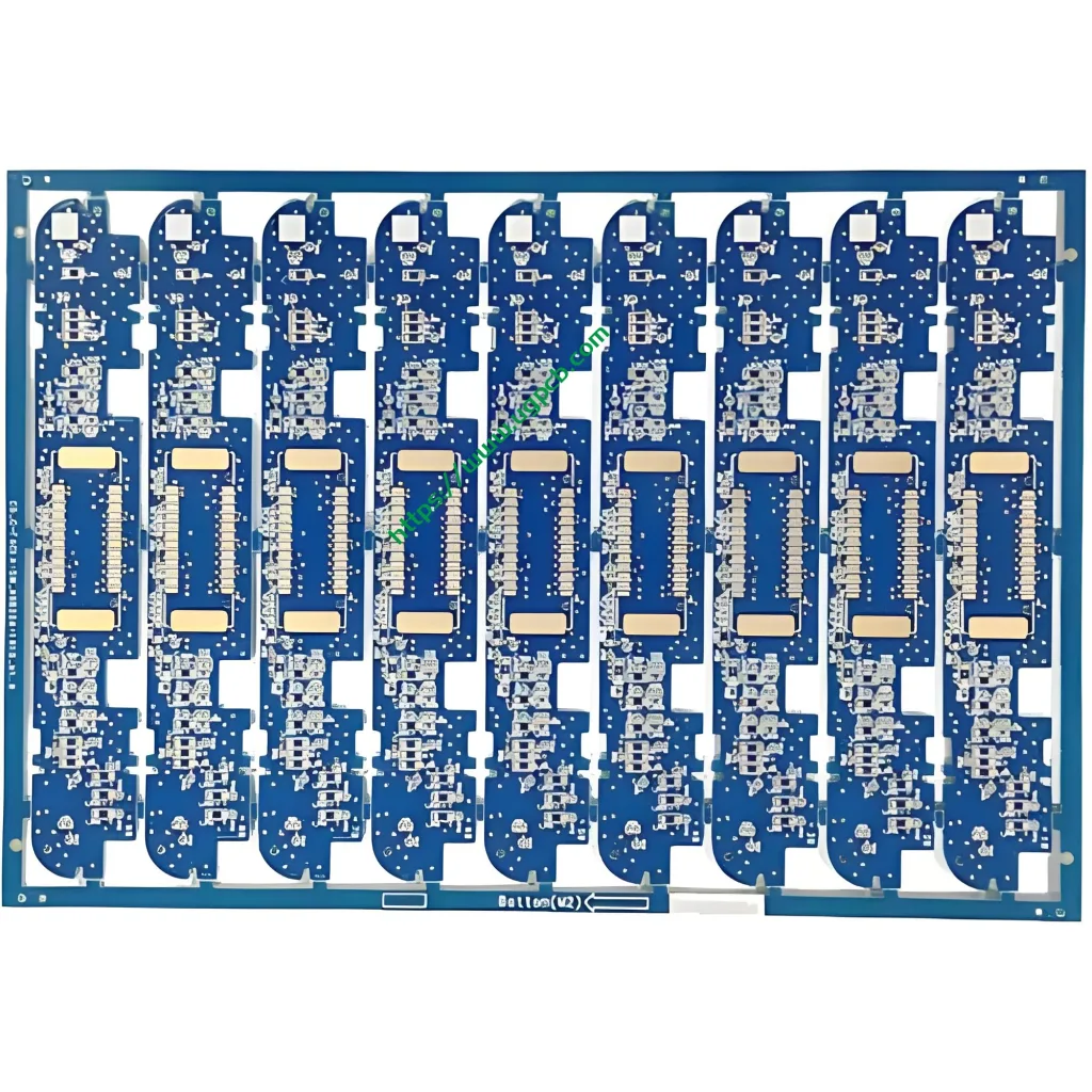
Esseplaca de circuito de controle do motor do robô medidas 96.83 × 30.6 mm com um 1.6 espessura da placa mm. Possui uma estrutura de fiação dupla face (2 camadas) que atende aos requisitos de espaço de sistemas de controle robóticos compactos. O produto oferece uma abertura mínima de 0.27 milímetros, largura/espaçamento do traço de 0.32/0.382 milímetros, e espessura da folha de cobre de 35/35 μm (1 onças de cobre em ambos os lados). O tratamento de superfície usa OSP (Conservantes orgânicos de soldabilidade) acabamento antioxidante. A máscara de solda vem em azul, e a legenda aparece em branco.
Definição de produto e conformidade com padrões
OPCB de controle de motor de robô é uma placa de circuito impresso especializada para acionamentos conjuntos robóticos, controle de servo motor, cartões de controle de movimento, e aplicações semelhantes. Este PCB transmite sinais de acionamento do motor, distribui poder, e executa lógica de controle. Funciona como um componente crítico no robô “sistema nervoso.”
Este produto é fabricado e projetado em estrita conformidade com os seguintes padrões internacionais:
- IPC-4101E/21 (Especificação de materiais básicos para placas impressas rígidas e multicamadas): O laminado KB6160A atende a esta especificação.
- IPC-6012E (Especificação de qualificação e desempenho para placas impressas rígidas): Isto cobre os requisitos de qualificação e desempenho para placas dupla-face.
- IPC-A-600K (Aceitabilidade de placas impressas): Isso serve como o padrão de aceitação ilustrado.
- IPC-4555 (Especificação de desempenho para conservantes orgânicos de soldabilidade em alta temperatura para placas impressas): Isso rege o processo de acabamento superficial OSP.
- UL 94 V-0 (Padrão de inflamabilidade): Isto representa a mais alta classificação de retardamento de chama.
Fonte de dados: As informações padrão acima vêm do IPC (Associação conectando indústrias eletrônicas) documentos padrão oficiais e UL (Laboratórios de subscritores) padrões de segurança.
Destaques do design
Seleção de materiais – As principais vantagens do KB6160A
KB6160A é um laminado revestido de cobre com tecido de vidro epóxi FR-4 convencional da Kingboard Laminates Holdings. Os principais parâmetros de desempenho aparecem abaixo:
| Propriedade | Método de teste (IPC-TM-650) | Especificação | Valor típico |
|---|---|---|---|
| Temperatura de transição vítrea (Tg) | 2.4.25 (DSC) | ≥130℃ | 135℃ |
| Estresse térmico (288℃ Flutuação de solda) | 2.4.13.1 | ≥10s | ≥180s |
| CTE (a1) Eixo Z | 2.4.24 (TMA) | - | 58 ppm/℃ |
| CTE (a2) Eixo Z | 2.4.24 (TMA) | - | 286 ppm/℃ |
| Temperatura de decomposição térmica (Td) | 2.4.24.6 (TGA) | - | 305℃ |
| Inflamabilidade (Classificação de chama) | UL 94 | V-0 | V-0 |
| Resistividade da superfície | 2.5.17.1 | ≥1,0×10⁴MΩ | 1.0×10⁶MΩ |
| Resistividade de volume | 2.5.17.1 | ≥1,0×10⁶ MΩ·cm | 1.0×10⁸ MΩ·cm |
| Constante dielétrica (@1MHz) | 2.5.5.2 | ≤5,4 | 4.58 |
| Fator de dissipação (@1MHz) | 2.5.5.2 | ≤0,035 | 0.022 |
| Resistência à casca de cobre (125℃) | 2.4.8 | ≥0,70 N/mm | 1.70 N/mm |
| Força de flexão (Urdidura) | 2.4.4 | ≥415 N/mm² | 565 N/mm² |
Fonte de dados: Os dados acima vêm da documentação técnica oficial do produto Kingboard Laminates Holdings e dos padrões de método de teste IPC-TM-650.
O laminado KB6160A oferece esses recursos principais:
- Bloqueio UVB e compatibilidade AOI: O material suporta bloqueio de luz UV e inspeção óptica automática (AOI). Isso melhora a eficiência e a precisão da produção de PCB.
- Excelente estabilidade dimensional: Os valores típicos de empenamento atingem apenas 0.17%/0.35%, bem abaixo do requisito padrão IPC de ≤1,0%.
- Desempenho térmico superior: Tg ≥130℃ (típico 135℃) com resistência ao estresse térmico de ≥180 segundos a 288°C de flutuação de solda.
- Excelentes propriedades mecânicas: A resistência à flexão típica atinge 565 N/mm².
Largura/espaçamento do traçado e design de abertura
Este produto apresenta uma abertura mínima de0.27 milímetros e largura/espaçamento do traço de0.32/0.382 milímetros. De acordo com IPC-2221, o padrão de design de base para todos os documentos da série IPC-2220, a capacidade de condução de corrente do condutor segue esta fórmula:
I = k × ΔT ^ 0,44 × A ^ 0,725
Onde I representa a capacidade de transporte de corrente (UM), k é o fator de correção (0.024 para camadas internas, 0.048 para camadas externas), ΔT é o aumento da temperatura (℃), e A é a área da seção transversal do condutor (mil²). Para condutores de camada externa com aumento de temperatura de 10°C, um 0.32 mm largura do traço (aproximadamente 12.6 mil) com 35 μm (1 onças) espessura do cobre fornece aproximadamente1.2 UM capacidade atual. Este projeto oferece suporte total à transmissão de sinal e aos requisitos moderados de acionamento de corrente para aplicações de controle de motores robóticos.
Espessura da placa e empilhamento de camadas
O 1.6 milímetros espessura da placa representa a espessura padrão para rígido PCB. Equilibra resistência mecânica com desempenho elétrico. O frente e verso (2-camada) a estrutura de fiação permite o particionamento eficaz da camada de energia e sinal dentro de um espaço limitado. Isso atende aos princípios de partição funcional dos circuitos de controle de motores robóticos, separando claramente o acionamento do motor, controlador principal, interface do sensor, e módulos de gerenciamento de energia.
Princípio Operacional
OPCB de controle de motor de robô funciona como o “centro neural” dentro de sistemas robóticos. Seu princípio de funcionamento pode ser compreendido através de diversas camadas:
Transmissão de sinal: Traços de cobre na PCB formam redes elétricas que transmitem com precisão sinais de controle do MCU principal (microcontrolador) para chips de driver de motor, como drivers de portão e pré-drivers. O 0.32 largura de traço em mm garante a integridade do sinal. O 0.27 A abertura mínima de mm suporta pacotes de componentes de alta densidade, incluindo QFN e BGA.
Unidade de força: Frente e verso 1 onças (35 μm) o cobre fornece ampla capacidade de transporte de corrente para altas correntes transitórias exigidas pelos acionamentos do motor. Componentes de alta potência são colocados perto das bordas da placa para facilitar a dissipação de calor.
Compatibilidade eletromagnética (Emc): O projeto de aterramento adequado e as estratégias de roteamento suprimem efetivamente a interferência eletromagnética (EMI) gerado durante a comutação do motor. Isso garante sinais de controle limpos em todo o sistema.
Aplicações de produtos
Esseplaca de circuito de controle do motor do robô atende as seguintes aplicações:
- Controle de acionamento conjunto de robô industrial: Controle de servo motor para braços robóticos multieixos
- Controle de movimento do robô de serviço: Feedback do acionamento do chassi e da velocidade das rodas para robôs de entrega e robôs de guia
- Plataformas de robôs educacionais: Painéis de controle para robótica didática e laboratorial
- Sistemas de controle de vôo UAV: Regulação e controle da velocidade do motor
- Automação residencial inteligente: Controle de acionamento motorizado para cortinas elétricas e fechaduras inteligentes
- Equipamento de automação de escritório: Controle de motor para impressoras e copiadoras
- Equipamento de comunicação: Controle do motor do ventilador de resfriamento para estações base e switches
Classificação do Produto
Este produto pode ser classificado cientificamente em múltiplas dimensões de acordo com os padrões internacionais de placas de circuito impresso:
| Dimensão de Classificação | Categoria | Norma Governante |
|---|---|---|
| Tipo de material base | Placa impressa rígida FR-4 | IPC-4101E/21 |
| Contagem de camadas condutoras | Placa Dupla Face (2-Camada) | IPC-6012E |
| Por tipo | Orifício revestido (PTH) Placa Dupla Face | IPC-6012E |
| Retardância da chama | UL 94 V-0 Avaliado | UL 94 |
| Acabamento superficial | OSP (Conservantes orgânicos de soldabilidade) | IPC-4555 |
| Domínio do Aplicativo | PCB de controle robótico/industrial | - |
Fonte de dados: Os padrões de classificação são baseados em IPC-4101E, IPC-6012E, IPC-4555, e UL 94 especificações internacionais.
Materiais utilizados
Material de base – Laminado de tecido de vidro epóxi revestido de cobre KB6160A
KB6160A pertence aoLaminado revestido de cobre com tecido de vidro epóxi FR-4 família. Sua composição material inclui:
- Reforço: Tecido de vidro E de grau eletrônico
- Fichário: Resina epóxi retardante de chama
- Folha de cobre: Eletrodepositado (DE) cobre, 35 μm (1 onças) grossura
- Sistema retardador de chama: UL 94 V-0 aditivos retardadores de chama compatíveis
Acabamento Superficial – OSP (Conservantes orgânicos de soldabilidade)
OSP é um revestimento orgânico fino aplicado em superfícies de cobre nu. Previne a oxidação do cobre e preserva a soldabilidade. De acordo com IPC-4555, a vida útil dos revestimentos OSP éum mínimo de seis meses.
Vantagens do acabamento superficial OSP:
- Econômico: Mais econômico que ENIG (Ouro de imersão em níquel eletrolítico) ou HASL (Nivelamento de solda com ar quente)
- Ecologicamente correto: Totalmente compatível com processos de soldagem sem chumbo
- Boa soldabilidade: Adequado para produtos com ciclos de vida curtos a médios ou ambientes benignos
Máscara de solda e legenda
- Máscara de solda: Tinta azul que fornece proteção de isolamento e evita pontes de solda
- Lenda: Tinta branca para identificação de componentes e orientação de montagem
Resumo dos parâmetros de desempenho
| Parâmetro | Especificação |
|---|---|
| Tipo laminado | KB6160A (Kingboard FR-4) |
| Espessura da placa | 1.6 milímetros |
| Contagem de camadas | 2 Camadas (Frente e verso) |
| Tamanho da placa | 96.83 × 30.6 milímetros |
| Abertura Mínima | 0.27 milímetros |
| Largura mínima de traços | 0.32 milímetros |
| Espaçamento Mínimo de Traçado | 0.382 milímetros |
| Espessura da folha de cobre | 35/35 μm (1 oz ambos os lados) |
| Acabamento superficial | Antioxidante OSP |
| Cor da máscara de solda | Azul |
| Cor da legenda | Branco |
| Tg (Temperatura de transição vítrea) | ≥130℃ (135 ℃ típico) |
| Classificação de chama | UL 94 V-0 |
| Estresse térmico (288℃) | ≥10s (Típico ≥180 s) |
Características estruturais
- Roteamento frente e verso: Ambas as camadas superior e inferior carregam circuitos, aumentando efetivamente a densidade de roteamento
- Orifício banhado (PTH) projeto: Permite a interconexão elétrica entre camadas
- Proteção de superfície OSP: A proteção contra oxidação da superfície de cobre garante confiabilidade de soldagem
- Máscara de solda azul com legenda branca: O contraste visual claro facilita a montagem e a inspeção
- 1.6 mm espessura padrão da placa: Equilibra a resistência mecânica com fabricação padronizada
Processo de fabricação
UGPCB fabrica oPCB de controle de motor de robô através deste fluxo de processo padronizado:
- Corte de materiais: Grandes painéis revestidos de cobre KB6160A são cortados em tamanhos de painel de produção
- Perfuração: CNC perfuração de controle numérico atinge o 0.27 abertura mínima mm
- Cobre eletrolítico/revestimento de painel: Deposição química de cobre seguida de galvanoplastia em painel para metalização de furos
- Transferência de padrão de camada externa: Laminação → exposição → desenvolvimento cria o padrão do circuito
- Revestimento padrão: Resistência de cobre e estanho-chumbo são galvanizadas no padrão do circuito
- Gravura: A folha de cobre exposta é removida para formar os circuitos finais
- Decapagem de estanho: A resistência estanho-chumbo é removida
- Tratamento de superfície OSP: O preservativo orgânico de soldabilidade OSP é aplicado de acordo com IPC-4555
- Impressão de máscara de solda: A tinta azul da máscara de solda é aplicada, expor, e desenvolvido
- Impressão de legenda: Caracteres de identificação brancos são impressos em tela
- Roteamento de perfil: O roteamento CNC constitui o final 96.83 × 30.6 dimensões mm
- Teste elétrico: Sonda voadora ou teste universal verifica condições de abertura/curto
- Inspeção final: Inspeção visual e dimensional conforme IPC-A-600K
- Embalagem e envio: Embalagem a vácuo com barreira contra umidade
Cenários de aplicação
Cenário 1: Controle de Servo Drive de Robô Industrial
Em robôs industriais de seis eixos, essePCB serve como placa de controle do servo driver. Ele recebe comandos de movimento do computador host. Os sinais de controle PWM viajam através 0.32 mm rastreia os estágios do driver IGBT ou MOSFET, alcançando torque preciso e controle de velocidade de servo motores.
Cenário 2: Acionamento do chassi do robô de serviço
Em robôs de entrega e AGVs (Veículos guiados automaticamente), esseplaca de circuito funciona como o núcleo para controle de acionamento independente de motor duplo. Ele controla de forma independente as velocidades e a direção das rodas motrizes esquerda e direita, permitindo deslocamento em linha reta e rotação no local.
Cenário 3: Plataformas educacionais de desenvolvimento de robôs
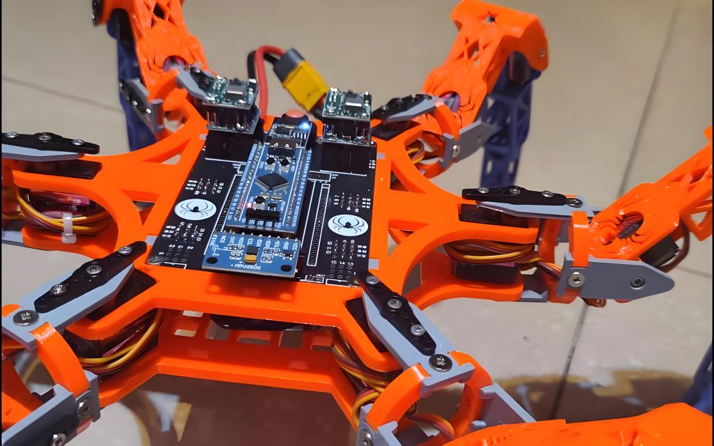
Em laboratórios de robótica universitários e espaços maker, essePCB de controle de motor de robô serve como placa principal para sistemas de controle robóticos. Ele apoia o desenvolvimento dos alunos e a verificação de algoritmos de acionamento de motores, incluindo FOC (Controle Orientado a Campo) e regulação de velocidade PID.
Cenário 4: Controle de velocidade do motor UAV
Em quadricópteros, este PCB pode funcionar como ESC (Controlador eletrônico de velocidade) placa de controle. Ele converte comandos do controlador de vôo em sinais de acionamento do motor, alcançando controle de resposta de alta velocidade de motores sem escova.
Por que escolher a PCB de controle de motor de robô da UGPCB?
- Conformidade total com os padrões internacionais: Os produtos são projetados e fabricados de acordo com IPC-4101E/21, IPC-6012E, IPC-A-600K, IPC-4555, e UL 94 V-0
- Garantia de material premium: Laminado Kingboard KB6160A FR-4 com Tg ≥130℃, UL 94 V-0 Classificação de chama, e ≥180 segundos de resistência ao estresse térmico
- Fabricação de alta precisão: 0.27 abertura mínima mm e 0.32 largura mínima de traço em mm atende aos requisitos de roteamento de alta densidade
- Serviço completo: Suporte de cadeia completa, desde otimização de design de PCB e fornecimento de componentes até montagem SMT/DIP e testes funcionais
- 10+ anos de experiência no setor: Servindo 3,000 clientes empresariais em todo o mundo
UGPCB é um fornecedor líder mundial de design de PCB, fabricação, e serviços de montagem PCBA. Fundado em 2014, a empresa está comprometida em fornecer soluções de PCB de alta precisão e altamente confiáveis para clientes em todo o mundo.
Obtenha um orçamento e amostras hoje
UGPCB apoia seuPCB de controle de motor de robô projeto com:
- ✅ DFM grátis (Design para Fabricação) relatórios
- ✅ Prototipagem rápida com 24-hora entrega disponível
- ✅ Produção em volume com 20%+ taxas de rendimento acima da média da indústria
- ✅ Equipe profissional de engenharia fornecendo suporte técnico
📧Contate-nos para um orçamento gratuito: Visite o site da UGPCB para enviar seus arquivos Gerber e BOM. Receba uma cotação automatizada líder do setor.
📞Linha direta: Entre em contato conosco através do chat online ou e-mail do nosso site.
Declaração de fonte de dados
Todos os dados técnicos e informações padrão citados neste artigo vêm das seguintes fontes confiáveis:
- Kingboard Laminados Holdings Ltd. — Documentação técnica do produto KB-6160A (Informações técnicas da base de conhecimento)
- IPC (Associação conectando indústrias eletrônicas) — Especificação IPC-4101E/21 para materiais de base para placas impressas rígidas e multicamadas, Especificação de qualificação e desempenho IPC-6012E para placas impressas rígidas, Aceitabilidade IPC-A-600K de placas impressas, Especificação de desempenho IPC-4555 para conservantes orgânicos de soldabilidade em alta temperatura (OSP) para placas impressas, Manual de métodos de teste IPC-TM-650, Padrão genérico IPC-2221 para design de placas impressas
- UL (Laboratórios de subscritores) - UL 94 Norma para testes de inflamabilidade de materiais plásticos para peças em dispositivos e eletrodomésticos
- Banco de dados de materiais PCBWay — Parâmetros técnicos KB-6160/6160A/6160C
- Documentação Técnica OSHPark — Folha de especificações do substrato KB6160A
Isenção de responsabilidade: Os valores típicos acima são dados de testes laboratoriais fornecidos apenas para referência. O desempenho real do produto pode variar dependendo dos processos de fabricação e ambientes de aplicação.













