

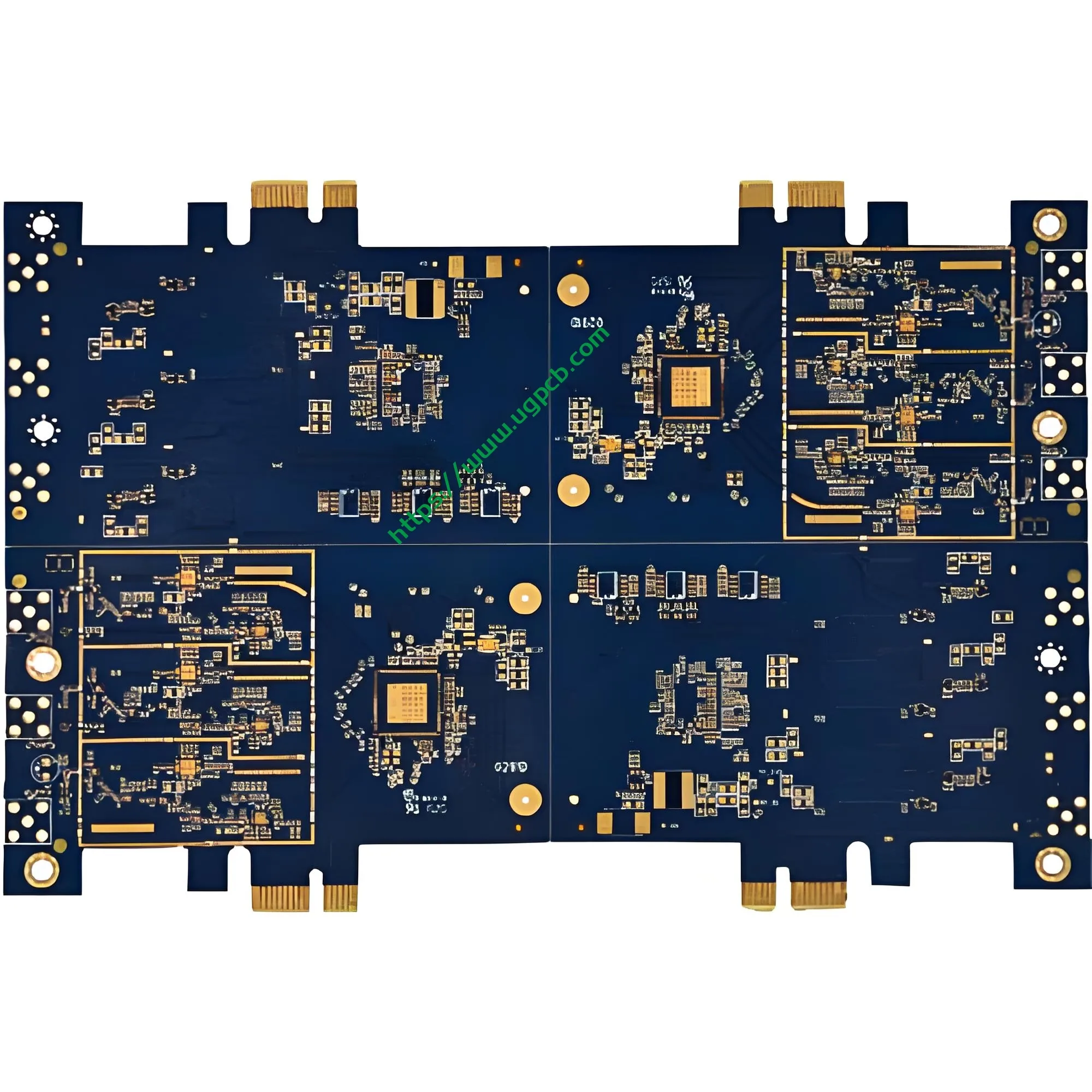
Descripción general del producto: ¿Qué es una PCB de disco duro mecánico de computadora??
Un disco duro mecánico de computadora tarjeta de circuito impreso (Placa de circuito impreso) Es el componente de control eléctrico más crítico dentro de una unidad de disco duro. (disco duro). Esta placa lleva el chip controlador principal., memoria caché, circuitos de administración de energía, y varios conectores de interfaz. Coordina las operaciones de lectura/escritura del cabezal., control del motor del husillo, y comunicación de datos entre el host y el medio de almacenamiento.
UGPCB presenta estePCB de disco duro mecánico de computadora fabricado con estándar de la industria Material de fibra de vidrio FR4. El tablero mide 1,6 mm de espesor con doble cara. (2-capa) diseño. Sus dimensiones precisas son 53.68 x 42,7 mm, Diseñado específicamente para dispositivos de almacenamiento de disco duro mecánico de 3,5 pulgadas.. Como el “centro neural” del disco duro, La calidad y el rendimiento de esta PCB determinan directamente las tasas de transferencia de datos., estabilidad de lectura/escritura, y vida útil general.
En el mundo actual impulsado por los datos, Los discos duros mecánicos mantienen una posición insustituible en los centros de datos., computadoras personales, vigilancia de seguridad, y almacenamiento en la nube debido a su gran capacidad y bajo coste por gigabyte. Como componente central de los discos duros, elplaca de circuito del disco duro exige calidad y confiabilidad excepcionales.
Definición del producto y clasificación científica
Definición del producto
APCB de disco duro mecánico de computadora Es una placa de circuito impreso rígida diseñada específicamente para uso interno dentro de unidades de disco duro mecánicas. (disco duro). Lleva el controlador principal, memoria caché, circuitos de administración de energía, y conectores de interfaz para permitir el control de lectura/escritura de datos, accionamiento motorizado, y comunicación con el anfitrión.
Clasificación científica
Según IPC-6012FEspecificación de calificación y rendimiento para tableros impresos rígidos, este producto cae dentro de las siguientes categorías de clasificación científica:
| Dimensión de clasificación | Categoría |
|---|---|
| Por estructura | Tablero rígido impreso a doble cara |
| Por recuento de capas | 2-Tablero de capas (2l) |
| Por tipo de vía | Con orificios pasantes chapados (PTH) |
| Por sustrato | Fibra de vidrio epoxi FR4 |
| Por clasificación de inflamabilidad | UL 94 V-0 (Calificación retardante de llama más alta) |
| Por acabado superficial | Chapado en oro |
| Por clase de rendimiento IPC | Clase 2 (Productos electrónicos de servicio dedicado) |
Según IPC-6012F, este producto es unTablero rígido impreso a doble cara con orificios pasantes. Cumple con la clase IPC 2 Requisitos para equipos electrónicos de servicio dedicado., Garantizar la confiabilidad bajo operación continua del disco duro., Variaciones de temperatura, y interferencia electromagnética.
Especificaciones de diseño y parámetros técnicos.
Material de sustrato: Fibra de vidrio FR4
Este producto utiliza FR4 (Retardante de llama 4) como material base, el laminado rígido más utilizado en la industria de PCB. FR4 consiste en un aglutinante de resina epoxi reforzado con tela tejida de fibra de vidrio.. Las ventajas clave incluyen:
- Resistencia mecánica superior: El refuerzo de fibra de vidrio proporciona una excelente resistencia a la flexión y estabilidad dimensional.
- Excelente aislamiento eléctrico: Resistividad de alto volumen y constante dieléctrica estable.
- UL 94 V-0 calificación de inflamabilidad: La llama se autoextingue en el interior. 10 segundos después de retirar la llama sin goteo
- Excelente resistencia térmica: TG (temperatura de transición vítrea) ≥135°C, compatible con procesos de soldadura sin plomo
Grosor del tablero y número de capas: 1.6mm Diseño de doble cara
Grosor del tablero: 1.6milímetros – Esto representa el “espesor dorado” en la industria de PCB y la especificación más típica para placas rígidas de doble cara según IPC-6012. El espesor de 1,6 mm logra un equilibrio óptimo entre resistencia mecánica, resistencia a la flexión, y costo de fabricación.
Según IPC-6012F, La tolerancia del espesor del tablero terminado para un espesor nominal de 1,6 mm es± 10%, produciendo un rango aceptable de1.44mm a 1,76 mm.
Recuento de capas: 2 capas (2l) – El diseño de doble cara satisface los requisitos de complejidad de enrutamiento de los circuitos de disco duro y al mismo tiempo logra un equilibrio óptimo entre costo y rendimiento.. Tanto la capa superior como la inferior llevan rastros., con agujeros pasantes chapados (PTH) proporcionar conexiones eléctricas entre capas.
Especificaciones dimensionales precisas
Dimensiones del contorno: 53.68 x 42,7 mm
UGPCB personaliza con precisión estas dimensiones basándose en los principales estándares industriales de discos duros mecánicos de 3,5 pulgadas., Garantizar la compatibilidad física con el alojamiento del disco., motor de husillo, y conjunto de brazo actuador. Los 53,68 mm de largo y 42,7 mm de ancho utilizan completamente el espacio interno limitado del disco duro al tiempo que maximizan el área funcional del circuito..
Parámetros de enrutamiento de precisión
Diámetro mínimo del agujero: 0.22milímetros
El diámetro mínimo del orificio de 0,22 mm representa un requisito de precisión de perforación mecánica relativamente alto.. La relación de aspecto (espesor del tablero al diámetro del agujero) es1.6 / 0.22 ≈ 7.27:1, bien dentro del límite superior de perforación mecánica convencional de ≤8:1. Esto garantiza un espesor uniforme del revestimiento de cobre y confiabilidad en las paredes del orificio..
Ancho de línea / interlineado: 0.37 x 0,42 mm
El enrutamiento de precisión con un ancho de línea de 0,37 mm y un espacio entre líneas de 0,42 mm garantiza la integridad de la señal y al mismo tiempo proporciona suficiente espacio de enrutamiento para buses de datos de alta velocidad.. Esta combinación de parámetros logra un equilibrio ideal entre el rendimiento de fabricación y el rendimiento eléctrico..
Espesor de lámina de cobre: 35/35μm (1 onz)
Tanto las láminas de cobre de la capa superior como la inferior miden35μm (1 onz) , que representa el espesor típico de cobre del conductor externo para placas impresas rígidas según IPC-6012F.
Según IPC-D-275, La capacidad de transporte de corriente del conductor externo se calcula de la siguiente manera.:
yo = 0.0647 × (ΔT)^0,4281 × (A)^0.6734
Dónde:
- I = Capacidad máxima de transporte de corriente (A)
- ΔT = Aumento de temperatura permitido (°C)
- A = Área de la sección transversal del conductor (mm²)
Para lámina de cobre de 35 μm con un ancho de línea de 1 mm, el área de la sección transversal del conductor A = 0,035 mm². Con un aumento de temperatura de 10°C, este conductor puede transportar aproximadamente1.0A.
Con un ancho de línea de 0,37 mm, la capacidad de transporte de corriente correspondiente es aproximadamente0.37A (con un aumento de temperatura de 10°C), Cumplir plenamente con los requisitos actuales de líneas de señal y alimentación en circuitos de disco duro..
Acabado superficial: Chapado en oro
Este producto utilizaChapado en oro como acabado superficial, con una capa de níquel (2-3μm) depositado primero, seguido de una capa de oro (≥0,025 μm) en las superficies de las almohadillas.
Ventajas clave del baño de oro:
- Excepcional resistencia al desgaste: La dura capa de oro resiste repetidos ciclos de apareamiento.
- Resistencia de contacto extremadamente baja: Garantiza una transmisión de señal estable y confiable
- Excelente soldabilidad: La superficie del oro resiste la oxidación., permitiendo una alta confiabilidad de soldadura
- Estabilidad de almacenamiento a largo plazo: La capa de oro protege eficazmente las superficies de cobre de la oxidación y la corrosión.
La capa de níquel sirve como barrera de difusión., prevenir la interdifusión entre cobre y oro y evitar la formación de compuestos intermetálicos frágiles de cobre y oro, garantizar fundamentalmente la fiabilidad a largo plazo.
Máscara de soldadura y leyenda: Máscara azul con personajes blancos.
Color de máscara de soldadura: Azul
La máscara de soldadura azul proporciona una identificación visual distintiva al mismo tiempo que ofrece una excelente protección de aislamiento y resistencia a la humedad.. La máscara de soldadura cubre todas las áreas de enrutamiento excepto las almohadillas., Previene eficazmente puentes de soldadura y cortocircuitos durante el montaje..
Color de leyenda: Blanco
La impresión de leyenda blanca en la máscara de soldadura azul crea un alto contraste.. Designadores de referencia de componentes, marcas de polaridad, y la información de la versión siguen siendo claramente legibles, facilitando enormemente la colocación de SMT y la posterior inspección y reparación..
Principio de funcionamiento: ¿Cómo funciona el almacenamiento de datos de la unidad HDD PCB??
La PCB del disco duro mecánico de la computadora funciona en los siguientes niveles:
Decodificación y ejecución de comandos
Cuando la computadora envía comandos de lectura/escritura al disco duro, Estos comandos se transmiten a través de la interfaz SATA al chip controlador en la PCB.. El chip controlador decodifica los comandos y envía señales de control a través de las pistas de PCB al controlador del actuador y al motor del husillo..
Control de lectura/escritura de datos
El canal de lectura/escritura en la PCB consta de un preamplificador, circuitos de lectura/escritura, y reloj de sincronización. Durante las operaciones de lectura, Las señales magnéticas débiles detectadas por el cabezal de lectura/escritura pasan a través del preamplificador y son convertidas por el canal de lectura/escritura en señales digitales., luego se transmite al host a través de la interfaz. Las operaciones de escritura siguen el camino inverso.
Gestión de energía
El módulo de gestión de voltaje/corriente en la PCB convierte la alimentación de +5 V y +12 V del host en los diversos voltajes requeridos por los diferentes componentes del disco duro.. Este módulo también implementa funciones avanzadas de administración de energía, incluida la optimización de energía., modo de suspensión automático, y protección de intercambio en caliente.
Caché de datos y firmware
El chip de caché en la PCB almacena temporalmente los datos a los que se accede con frecuencia para mejorar el rendimiento de lectura/escritura.. El chip de firmware almacena el microcódigo operativo del disco duro., controlar la lógica central, incluido el posicionamiento de la cabeza, mala gestión del sector, y monitoreo INTELIGENTE.
Especificaciones de rendimiento y estándares de calidad
Rendimiento eléctrico
| Parámetro | Especificación | Estándar de referencia |
|---|---|---|
| Resistencia de aislamiento | ≥10⁶ MΩ | IPC-6012F |
| Tensión de resistencia dieléctrica | ≥500 VCA (1 minuto) | IPC-6012F |
| Resistencia de conductores | ≤1,0 mΩ/cm | IPC-6012F |
| Impedancia característica | Controlado por diseño | IPC-6012F |
Rendimiento mecánico
| Parámetro | Especificación | Estándar de referencia |
|---|---|---|
| Tolerancia del espesor del tablero | ± 10% (1.44–1,76 mm) | IPC-6012F |
| Grosor del cobre de la pared del agujero | ≥20 μm (Clase 2) | IPC-6012F |
| Fuerza de pelado | ≥1,1N/mm | IPC-6012F |
| Calificación de inflamabilidad | UL 94 V-0 | UL 94 |
Inspección visual y dimensional
Según IPC-A-600KAceptabilidad de los tableros impresos, Los PCB terminados deben pasar una rigurosa inspección visual. (3 aumento de dioptrías, aproximadamente 1,75x) para asegurar que no haya rayones, burbujas, cobre expuesto, u otros defectos.
Proceso de fabricación y control de calidad.
Flujo de producción estándar
- Corte: Laminado revestido de cobre FR4 cortado al tamaño del panel
- Perforación: 0.22perforación mecánica de precisión mm
- Cobre no electrolítico / Revestimiento de paneles: Deposición química + galvanoplastia de panel completo
- Transferencia de patrones: Laminación de película seca → exposición → revelado → grabado
- Patrón de revestimiento: Acumulación de capa de cobre hasta 35μm
- Banda / Grabar al agua fuerte / Banda: Formación del patrón de circuito final
- Impresión de máscara de soldadura: Serigrafía de máscara de soldadura azul + curación
- Impresión de leyendas: Serigrafía leyenda blanca
- Chapado en oro: Chapado en níquel-oro en las superficies de las pastillas
- Enrutamiento: Enrutamiento CNC a 53.68 contorno de 42,7 mm
- Prueba eléctrica: sonda voladora / prueba de apertura-corto del accesorio
- Inspección FQC: 100% control de calidad final según IPC-A-600K
Sistema de control de calidad
UGPCB implementa estrictamente la clase IPC-6012F 2 Estándares con control de calidad de extremo a extremo desde los materiales entrantes hasta el envío.:
- inspección entrante: 100% inspección de laminados FR4, láminas de cobre, tintas, y otras materias primas
- Control en proceso: Puntos de control de calidad en cada paso del proceso con monitoreo SPC
- inspección AOI: 100% Inspección óptica automática para detectar defectos en el circuito.
- Pruebas de confiabilidad: Prueba de choque térmico, prueba de humedad, pruebas de soldabilidad
Escenarios de aplicación y valor de mercado
Escenarios de aplicación primaria
| Área de aplicación | Caso de uso específico | Requisitos de PCB |
|---|---|---|
| Computadoras personales | Disco duro de escritorio, disco duro externo para portátiles | Alta confiabilidad, larga vida útil |
| Centros de datos | Servidores de almacenamiento en la nube, matrices de almacenamiento empresarial | 24/7 operación continua |
| Vigilancia de seguridad | Grabadores de vídeo en red NVR, servidores de almacenamiento de vídeo | Escritura continua de alta capacidad |
| Electrónica de Consumo | Consolas de juegos, decodificadores, televisores inteligentes | Costo optimizado, operación estable |
| Recuperación de datos | Reemplazo y reparación de PCB de disco duro defectuoso | Compatibilidad precisa, enchufar y usar |

Perspectiva del mercado
Según QYR (QYInvestigación) estadística, El mercado mundial de PCB de disco duro mecánico mantiene un crecimiento constante. Aunque las unidades de estado sólido (SSD) están penetrando rápidamente en el mercado de consumo, Los discos duros mecánicos siguen dominando el almacenamiento de alta capacidad. (8tuberculosis y superior), almacenamiento en frío del centro de datos, y aplicaciones de vigilancia de seguridad debido a suventaja de costo por gigabyte yconfiabilidad de retención de datos a largo plazo.
¿Por qué elegir la PCB de disco duro mecánico para computadora de UGPCB??
Ventajas técnicas
- Fabricado estrictamente según las especificaciones internacionales IPC-6012F.
- 1.6El sustrato FR4 de mm con lámina de cobre de doble cara de 35 μm ofrece resistencia mecánica y rendimiento eléctrico.
- 0.22Diámetro del orificio de precisión de mm con ancho/espaciado de línea fina de 0,37/0,42 mm que admite requisitos de enrutamiento de alta densidad
Seguro de calidad
- El acabado superficial chapado en oro proporciona una baja resistencia al contacto, excelente soldabilidad, y estabilidad en almacenamiento a largo plazo
- La máscara de soldadura azul con leyenda blanca ofrece un alto contraste, fácil identificación, resistencia a la humedad, y aislamiento
- 100% Las pruebas eléctricas más la inspección AOI garantizan el envío sin defectos de cada PCB.
Compromiso de servicio
- Admite tanto la creación de prototipos en lotes pequeños como la producción de gran volumen
- Proporciona DFM profesional (Diseño para la fabricación) revisar
- Entrega rápida para satisfacer necesidades urgentes de reparación y producción en masa.
Solicite una cotización: obtenga su solución PCB HDD personalizada hoy
Si usted es un fabricante de discos duros, proveedor de servicios de recuperación de datos, o integrador de sistemas de vigilancia de seguridad, UGPCB ofrece PCB de disco duro mecánico para computadora de alta calidad adaptadas a sus necesidades.
Contáctenos hoy para:
- Hojas de datos de productos e informes de pruebas de confiabilidad.
- Servicios de diseño personalizado y revisión DFM
- Propuestas de precios por volumen y cronogramas de entrega
👉Haga clic para consultar – El equipo técnico de UGPCB responderá en el plazo 24 horas con su solución personalizada!
Declaración de fuente de datos
Las normas técnicas y los datos citados en este documento derivan de las siguientes fuentes autorizadas.:
- IPC-6012F: Especificación de calificación y rendimiento para tableros impresos rígidos, IPC – Asociación Mundial de Electrónica, Octubre 2023
- IPC-A-600K: Aceptabilidad de los tableros impresos, IPC – Asociación Mundial de Electrónica, Julio 2020
- IPC-D-275: Estándar de diseño para tableros impresos rígidos y conjuntos de tableros impresos rígidos
- UL 94: Norma de Seguridad de Inflamabilidad de Materiales Plásticos, Laboratorios aseguradores
- Tolerancia del espesor de la placa IPC-6012F: Espesor nominal ±10% (1.44mm – 1,76 mm)













