


Descripción general del producto
La UGPCB presenta la PCB de control de motor de robot, un doble cara de alta confiabilidad placa de circuito impreso Diseñado específicamente para sistemas robóticos de control de movimiento.. Este producto utiliza laminado de tela de vidrio epoxi revestido de cobre Kingboard KB6160A y sigue estrictamente los requisitos de la especificación IPC-4101E/21.. El material ofrece una excelente resistencia térmica., resistencia mecánica, y rendimiento eléctrico. Estas cualidades proporcionan una base de hardware sólida para aplicaciones de control y accionamiento de motores robóticos..
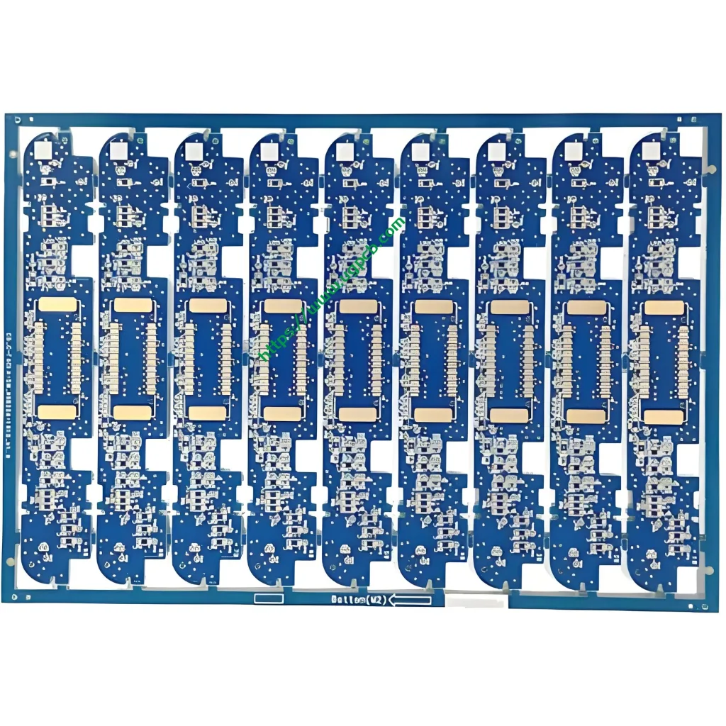
Esteplaca de circuito de control de motor de robot medidas 96.83 × 30.6 mm con un 1.6 mm de espesor del tablero. Cuenta con una estructura de cableado de doble cara. (2 capas) que cumple con los requisitos de espacio de los sistemas de control robóticos compactos. El producto ofrece una apertura mínima de 0.27 milímetros, ancho de traza/espaciado de 0.32/0.382 milímetros, y espesor de lámina de cobre de 35/35 μm (1 oz de cobre en ambos lados). El tratamiento superficial utiliza OSP. (Conservantes de soldadura orgánica) acabado antioxidante. La máscara de soldadura viene en azul., y la leyenda aparece en blanco.
Definición del producto y cumplimiento de estándares
ElPCB de control de motor de robot es una placa de circuito impreso especializada para accionamientos de articulaciones robóticas, control de servomotor, tarjetas de control de movimiento, y aplicaciones similares. Esta PCB transmite señales de accionamiento del motor., distribuye poder, y ejecuta la lógica de control. Funciona como un componente crítico en el funcionamiento del robot. “sistema nervioso.”
Este producto se fabrica y diseña en estricta conformidad con los siguientes estándares internacionales.:
- IPC-4101E/21 (Especificación de Materiales Base para Tableros Impresos Rígidos y Multicapa): El laminado KB6160A cumple con esta especificación.
- IPC-6012E (Especificación de calificación y rendimiento para tableros impresos rígidos): Esto cubre los requisitos de calificación y rendimiento para tableros de doble cara..
- IPC-A-600K (Aceptabilidad de los tableros impresos): Esto sirve como estándar de aceptación ilustrado..
- IPC-4555 (Especificación de rendimiento para conservantes orgánicos de soldabilidad a alta temperatura para tableros impresos): Esto rige el proceso de acabado de superficies OSP..
- UL 94 V-0 (Estándar de inflamabilidad): Esto representa la clasificación de retardo de llama más alta..
Fuente de datos: La información estándar anterior proviene del IPC. (Asociación que conecta industrias electrónicas) documentos estándar oficiales y UL (Laboratorios aseguradores) normas de seguridad.
Destacados de diseño
Selección de materiales: las principales ventajas de KB6160A
KB6160A es un laminado convencional revestido de cobre de tela de vidrio epoxi FR-4 de Kingboard Laminates Holdings. Los parámetros clave de rendimiento aparecen a continuación:
| Propiedad | Método de prueba (IPC-TM-650) | Especificación | Valor típico |
|---|---|---|---|
| Temperatura de transición vítrea (tg) | 2.4.25 (DSC) | ≥130℃ | 135℃ |
| Estrés térmico (288℃ Flotador de soldadura) | 2.4.13.1 | ≥10 segundos | ≥180 segundos |
| CTE (a1) Eje Z | 2.4.24 (TMA) | - | 58 PPM/℃ |
| CTE (a2) Eje Z | 2.4.24 (TMA) | - | 286 PPM/℃ |
| Temperatura de descomposición térmica (td) | 2.4.24.6 (TGA) | - | 305℃ |
| Inflamabilidad (Clasificación de llama) | UL 94 | V-0 | V-0 |
| Resistividad superficial | 2.5.17.1 | ≥1,0×10⁴ MΩ | 1.0×10⁶ MΩ |
| Resistividad de volumen | 2.5.17.1 | ≥1,0×10⁶ MΩ·cm | 1.0×10⁸ MΩ·cm |
| Constante dieléctrica (@1MHz) | 2.5.5.2 | ≤5,4 | 4.58 |
| Factor de disipación (@1MHz) | 2.5.5.2 | ≤0,035 | 0.022 |
| Resistencia al pelado de cobre (125℃) | 2.4.8 | ≥0,70 N/mm | 1.70 N/mm |
| Resistencia a la flexión (Urdimbre) | 2.4.4 | ≥415N/mm² | 565 N/mm² |
Fuente de datos: Los datos anteriores provienen de la documentación técnica oficial del producto de Kingboard Laminates Holdings y de los estándares del método de prueba IPC-TM-650..
El laminado KB6160A ofrece estas características principales:
- Bloqueo de UVB y compatibilidad con AOI: El material soporta el bloqueo de la luz ultravioleta y inspección óptica automática (AOI). Esto mejora la eficiencia y precisión de la producción de PCB..
- Excelente estabilidad dimensional: Los valores típicos de deformación alcanzan sólo 0.17%/0.35%, muy por debajo del requisito estándar IPC de ≤1,0%.
- Rendimiento térmico superior: Tg≥130℃ (típico 135 ℃) con resistencia al estrés térmico de ≥180 segundos a 288 ℃ flotador de soldadura.
- Excelentes propiedades mecánicas: La resistencia a la flexión típica alcanza 565 N/mm².
Ancho de trazado/espaciado y diseño de apertura
Este producto presenta una apertura mínima de0.27 milímetros y trazar el ancho/espaciado de0.32/0.382 milímetros. Según IPC-2221, el estándar de diseño de cimientos para todos los documentos de la serie IPC-2220, la capacidad de transporte de corriente del conductor sigue esta fórmula:
Yo = k × ΔT^0,44 × A^0,725
Donde I representa la capacidad de carga actual (A), k es el factor de corrección (0.024 para capas internas, 0.048 para capas exteriores), ΔT es el aumento de temperatura (℃), y A es el área de la sección transversal del conductor (mil²). Para conductores de capa exterior con un aumento de temperatura de 10 ℃, a 0.32 mm de ancho de traza (aproximadamente 12.6 mil) con 35 μm (1 onz) El espesor del cobre ofrece aproximadamente1.2 A capacidad actual. Este diseño es totalmente compatible con la transmisión de señales y los requisitos de accionamiento de corriente moderados para aplicaciones de control de motores robóticos..
Grosor del tablero y apilamiento de capas
El 1.6 milímetros El espesor del tablero representa el espesor estándar para rígidos. PCB. Equilibra la resistencia mecánica con el rendimiento eléctrico.. El de dos caras (2-capa) La estructura del cableado permite una partición efectiva de la capa de señal y energía dentro de un espacio limitado.. Esto cumple con los principios de partición funcional de los circuitos de control de motores robóticos., unidad de motor claramente separada, controlador principal, interfaz de sensores, y módulos de administración de energía.
Principio de funcionamiento
ElPCB de control de motor de robot funciona como el “centro neural” dentro de los sistemas robóticos. Su principio de funcionamiento se puede entender a través de varias capas.:
Transmisión de señal: Las pistas de cobre en la PCB forman redes eléctricas que transmiten con precisión señales de control desde la MCU principal. (microcontrolador) a chips de controladores de motor, como controladores de puerta y precontroladores. El 0.32 El ancho de traza en mm garantiza la integridad de la señal.. El 0.27 La apertura mínima de mm admite paquetes de componentes de alta densidad, incluidos QFN y BGA..
Unidad de potencia: De dos caras 1 onz (35 μm) El cobre proporciona una amplia capacidad de transporte de corriente para las altas corrientes transitorias requeridas por los motores.. Los componentes de alta potencia se colocan cerca de los bordes de la placa para facilitar la disipación del calor..
Compatibilidad electromagnética (CEM): El diseño adecuado de la conexión a tierra y las estrategias de enrutamiento suprimen eficazmente las interferencias electromagnéticas. (EMI) generado durante la conmutación del motor. Esto garantiza señales de control limpias en todo el sistema..
Aplicaciones de productos
Esteplaca de circuito de control de motor de robot sirve para las siguientes aplicaciones:
- Control de accionamiento de articulación de robot industrial: Control de servomotor para brazos robóticos multieje
- Control de movimiento del robot de servicio: Transmisión del chasis y retroalimentación de la velocidad de las ruedas para robots de reparto y robots guía
- Plataformas de robots educativos: Cuadros de control para robótica docente y de laboratorio.
- Sistemas de control de vuelo UAV: Regulación y control de la velocidad del motor.
- domótica inteligente: Control de accionamiento de motores para cortinas eléctricas y cerraduras inteligentes.
- Equipos de ofimática: Control de motores para impresoras y fotocopiadoras.
- Equipos de comunicaciones: Control del motor del ventilador de refrigeración para estaciones base e interruptores
Clasificación de productos
Este producto se puede clasificar científicamente en múltiples dimensiones de acuerdo con los estándares internacionales de placas de circuito impreso.:
| Dimensión de clasificación | Categoría | Estándar rector |
|---|---|---|
| Tipo de material base | Tablero impreso rígido FR-4 | IPC-4101E/21 |
| Recuento de capas conductoras | Tablero de doble cara (2-Capa) | IPC-6012E |
| Vía tipo | Orificio pasante chapado (PTH) Tablero de doble cara | IPC-6012E |
| Retardante de llama | UL 94 V-0 Clasificado | UL 94 |
| Acabado superficial | OSP (Conservantes de soldadura orgánica) | IPC-4555 |
| Dominio de aplicación | PCB de control industrial/robótica | - |
Fuente de datos: Los estándares de clasificación se basan en IPC-4101E., IPC-6012E, IPC-4555, y UL 94 especificaciones internacionales.
Materiales utilizados
Material base: laminado de tela de vidrio epoxi revestido de cobre KB6160A
KB6160A pertenece a laLaminado revestido de cobre de tela de vidrio epoxi FR-4 familia. Su composición material incluye:
- Reforzamiento: Tela de vidrio E de grado electrónico
- Aglutinante: Resina epoxi ignífuga
- Lámina de cobre: Electrodepositado (Edición) cobre, 35 μm (1 onz) espesor
- Sistema retardante de llama: UL 94 V-0 aditivos retardantes de llama compatibles
Acabado superficial: OSP (Conservantes de soldadura orgánica)
OSP es una fina capa orgánica que se aplica a superficies de cobre desnudas.. Previene la oxidación del cobre y preserva la soldabilidad.. Según IPC-4555, La vida útil de los recubrimientos OSP esun mínimo de seis meses.
Ventajas del acabado superficial OSP:
- Rentable: Más económico que ENIG (Oro de inmersión de níquel químico) o HASL (Nivelación de soldadura por aire caliente)
- Respetuoso con el medio ambiente: Totalmente compatible con procesos de soldadura sin plomo
- Buena soldabilidad: Adecuado para productos con ciclos de vida cortos a medianos o entornos benignos
Máscara de soldadura y leyenda
- Máscara de soldadura: Tinta azul que proporciona protección del aislamiento y evita puentes de soldadura.
- Leyenda: Tinta blanca para identificación de componentes y guía de montaje.
Resumen de parámetros de rendimiento
| Parámetro | Especificación |
|---|---|
| Tipo laminado | KB6160A (Tablero King FR-4) |
| Grosor del tablero | 1.6 milímetros |
| Recuento de capas | 2 capas (De dos caras) |
| Tamaño de tablero | 96.83 × 30.6 milímetros |
| Apertura mínima | 0.27 milímetros |
| Ancho mínimo de traza | 0.32 milímetros |
| Espaciado mínimo de seguimiento | 0.382 milímetros |
| Espesor de lámina de cobre | 35/35 μm (1 oz ambos lados) |
| Acabado superficial | OSP antioxidante |
| Color de máscara de soldadura | Azul |
| Color de leyenda | Blanco |
| tg (Temperatura de transición vítrea) | ≥130℃ (Típico 135 ℃) |
| Clasificación de llama | UL 94 V-0 |
| Estrés térmico (288℃) | ≥10 segundos (Típico ≥180 s) |
Características estructurales
- Enrutamiento de doble cara: Tanto la capa superior como la inferior llevan circuitos., aumentar efectivamente la densidad de enrutamiento
- Orificio pasante chapado (PTH) diseño: Permite la interconexión eléctrica entre capas.
- Protección de superficies OSP: La protección contra la oxidación de la superficie de cobre garantiza la confiabilidad de la soldadura
- Máscara de soldadura azul con leyenda blanca.: El claro contraste visual facilita el montaje y la inspección.
- 1.6 mm espesor de tablero estándar: Equilibra la resistencia mecánica con la fabricación estandarizada
Proceso de fabricación
UGPCB fabrica elPCB de control de motor de robot a través de este flujo de proceso estandarizado:
- corte de materiales: Los grandes paneles revestidos de cobre KB6160A se cortan a los tamaños de panel de producción
- Perforación: CNC La perforación con control numérico logra el 0.27 mm apertura mínima
- Recubrimiento de paneles/cobre no electrolítico: Deposición química de cobre seguida de galvanoplastia de paneles para metalización de orificios.
- Transferencia de patrón de capa exterior: Laminación → exposición → desarrollo crea el patrón del circuito
- Revestimiento de patrón: La resistencia de cobre y estaño-plomo está galvanizada en el patrón del circuito.
- Aguafuerte: Se retira la lámina de cobre expuesta para formar los circuitos finales.
- Decapado de estaño: Se elimina la resistencia de estaño-plomo.
- Tratamiento de superficie OSP: Se aplica conservante de soldabilidad orgánico OSP según IPC-4555.
- Impresión de máscara de soldadura: Se aplica tinta de máscara de soldadura azul., expuesto, y desarrollado
- Impresión de leyenda: Los caracteres de identificación blancos están serigrafiados.
- Enrutamiento de perfil: El enrutamiento CNC constituye el final 96.83 × 30.6 dimensiones en mm
- Pruebas electricas: La sonda voladora o la prueba universal verifican las condiciones de apertura/cortocircuito
- Inspección final: Inspección visual y dimensional según IPC-A-600K
- Embalaje y envío: Envasado al vacío con barrera contra la humedad.
Escenarios de aplicación
Guión 1: Control de servoaccionamiento de robot industrial
En robots industriales de seis ejes, estetarjeta de circuito impreso sirve como tablero de control del servocontrolador. Recibe comandos de movimiento desde la computadora host.. Las señales de control PWM viajan a través 0.32 mm de trazas a etapas de controlador IGBT o MOSFET, lograr un control preciso del par y la velocidad de los servomotores.
Guión 2: Servicio de accionamiento del chasis del robot
En robots de reparto y AGV (Vehículos guiados automatizados), estetarjeta de circuitos Funciona como núcleo para el control de accionamiento independiente de dos motores.. Controla de forma independiente la velocidad y la dirección de las ruedas motrices izquierda y derecha., permitiendo desplazamiento en línea recta y rotación en el lugar.
Guión 3: Plataformas de desarrollo de robots educativos
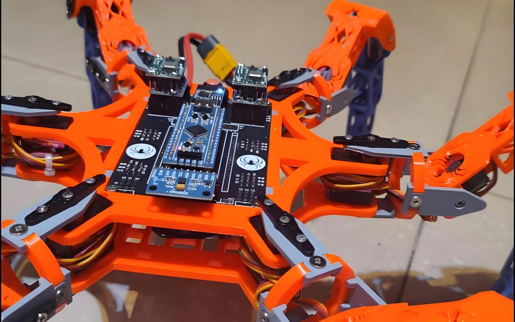
En laboratorios universitarios de robótica y espacios maker, estePCB de control de motor de robot sirve como placa central para sistemas de control robóticos. Apoya el desarrollo de los estudiantes y la verificación de algoritmos de accionamiento motorizado, incluido FOC. (Control orientado al campo) y regulación de velocidad PID.
Guión 4: Control de velocidad del motor UAV
En cuadricópteros, Este PCB puede funcionar como ESC (Controlador electrónico de velocidad) tablero de control. Convierte los comandos del controlador de vuelo en señales de accionamiento del motor., lograr un control de respuesta de alta velocidad de motores sin escobillas.
Por qué elegir la PCB de control de motores robóticos de UGPCB?
- Cumplimiento total de estándares internacionales: Los productos están diseñados y fabricados según IPC-4101E/21., IPC-6012E, IPC-A-600K, IPC-4555, y UL 94 V-0
- Garantía de materiales de primera calidad: Laminado Kingboard KB6160A FR-4 con Tg ≥130℃, UL 94 V-0 calificación de llamas, y ≥180 segundos de resistencia al estrés térmico
- Fabricación de alta precisión: 0.27 mm de apertura mínima y 0.32 mm de ancho mínimo de traza que cumple con los requisitos de enrutamiento de alta densidad
- Servicio integral: Soporte de cadena completa, desde la optimización del diseño de PCB y el abastecimiento de componentes hasta el ensamblaje SMT/DIP y las pruebas funcionales.
- 10+ años de experiencia en la industria: sirviendo 3,000 clientes empresariales a nivel mundial
UGPCB es un proveedor líder mundial de diseño de PCB, fabricación, y servicios de ensamblaje de PCBA. Fundado en 2014, La empresa se compromete a proporcionar soluciones de PCB de alta precisión y alta confiabilidad para clientes de todo el mundo..
Obtenga una cotización y muestras hoy
UGPCB apoya suPCB de control de motor de robot proyecto con:
- ✅ DFM gratuito (Diseño para la fabricación) informes
- ✅ Creación rápida de prototipos con 24-hora entrega disponible
- ✅ Producción en volumen con 20%+ tasas de rendimiento superiores al promedio de la industria
- ✅ Equipo de ingeniería profesional que brinda soporte técnico
📧Contáctenos para una cotización gratuita: Visite el sitio web de UGPCB para enviar sus archivos Gerber y BOM. Reciba una cotización automatizada líder en la industria.
📞Línea directa: Comuníquese con nosotros a través del chat en línea o correo electrónico de nuestro sitio web..
Declaración de fuente de datos
Todos los datos técnicos y la información estándar citada en este artículo provienen de las siguientes fuentes autorizadas.:
- Kingboard Laminates Holdings Ltd. — Documentación técnica del producto KB-6160A (Información técnica de KB)
- PCI (Asociación que conecta industrias electrónicas) — Especificación IPC-4101E/21 para materiales base para tableros impresos rígidos y multicapa, Especificación de rendimiento y calificación IPC-6012E para tableros impresos rígidos, IPC-A-600K Aceptabilidad de tableros impresos, Especificación de rendimiento IPC-4555 para conservantes orgánicos de soldabilidad a alta temperatura (OSP) para tableros impresos, Manual de métodos de prueba IPC-TM-650, IPC-2221 Norma genérica sobre diseño de tableros impresos
- UL (Laboratorios aseguradores) — UL 94 Norma para pruebas de inflamabilidad de materiales plásticos para piezas de dispositivos y electrodomésticos
- Base de datos de materiales PCBWay — Parámetros técnicos KB-6160/6160A/6160C
- Documentación técnica de OSHPark — Hoja de especificaciones del sustrato KB6160A
Descargo de responsabilidad: Los valores típicos anteriores son datos de pruebas de laboratorio proporcionados solo como referencia.. El rendimiento real del producto puede variar según los procesos de fabricación y los entornos de aplicación..













