
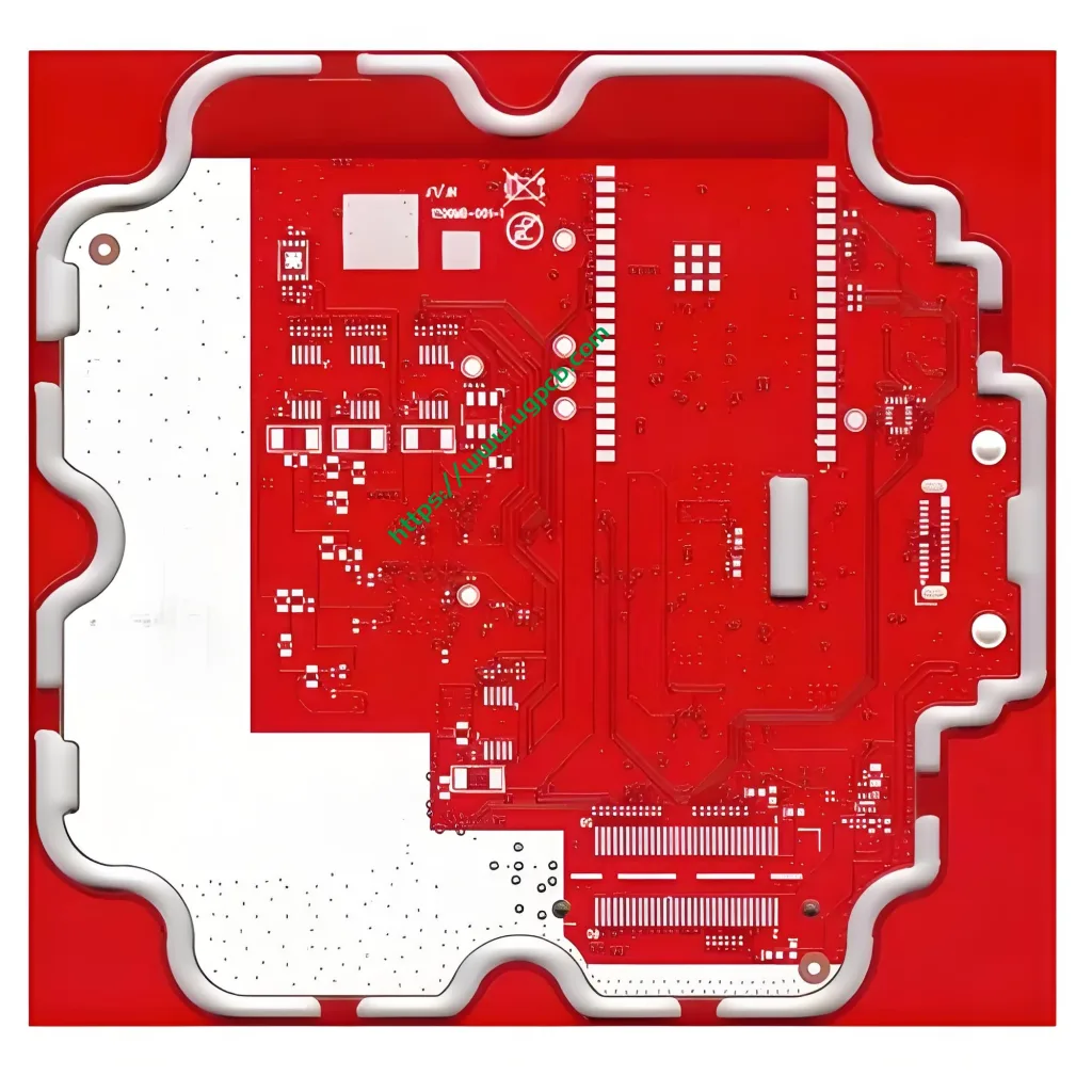
Descripción general de PCB de radar de onda milímetro
El radar de onda milimétrica utiliza principalmente PCB de radar 24 g y PCB de radar de 77 g, y la PCB de radar de onda milímetro se usa principalmente para la conducción automotriz de IA inteligente no tripulada.
Broad Application Prospects of Millimeter Wave Radar PCB
PCB de radar de onda milimétrica tiene amplias perspectivas de aplicación. Actualmente, UGPCB adopts Rogers RO3003G2+ITEQ IT180 to mass-produce 77GHz millimeter-wave radar PCB.
Importance of Radar PCB Material in Radar Sensor Design
Critical Component in Radar Sensor Design
Una característica común para diferentes diseños de PCB de radar para sensores de radar MMWave es la necesidad de materiales de PCB de radar de pérdida ultra baja para reducir las pérdidas de circuitos y aumentar la radiación de la antena.. El material PCB de radar es un componente crítico en el diseño del sensor de radar. Elegir el material de PCB de radar de radar correcto puede garantizar la estabilidad y consistencia del sensor de radar de onda milímetro.
Electrical Properties of Radar PCB Materials
How to Design the Performance of a Radar PCB
Primero, the electrical properties of radar PCB materials are the primary factor in designing radar sensors and selecting radar PCB materials. Selecting radar PCB materials with stable dielectric constant and ultra-low loss is critical to the performance of 77GHz mmWave radar. The stable dielectric constant and loss can make the antenna receive and transmit accurate phase, which can improve the gain, scanning angle or range of the antenna, and improve the accuracy of radar detection and positioning. The stability of the dielectric constant and loss characteristics of the PCB not only ensures the stability of different batches of materials, but also ensures that the variation within the same PCB board is small and has good stability.


