

EU. Visão geral do produto: PCB de precisão projetada para equipamentos estéticos
O instrumento de depilação a laser depende de um sistema de controle central. Este sistema dita segurança, estabilidade, e eficácia geral do tratamento. No coração deste sistema está oinstrumento de depilação a laser PCB. Este componente é tudo menos trivial.
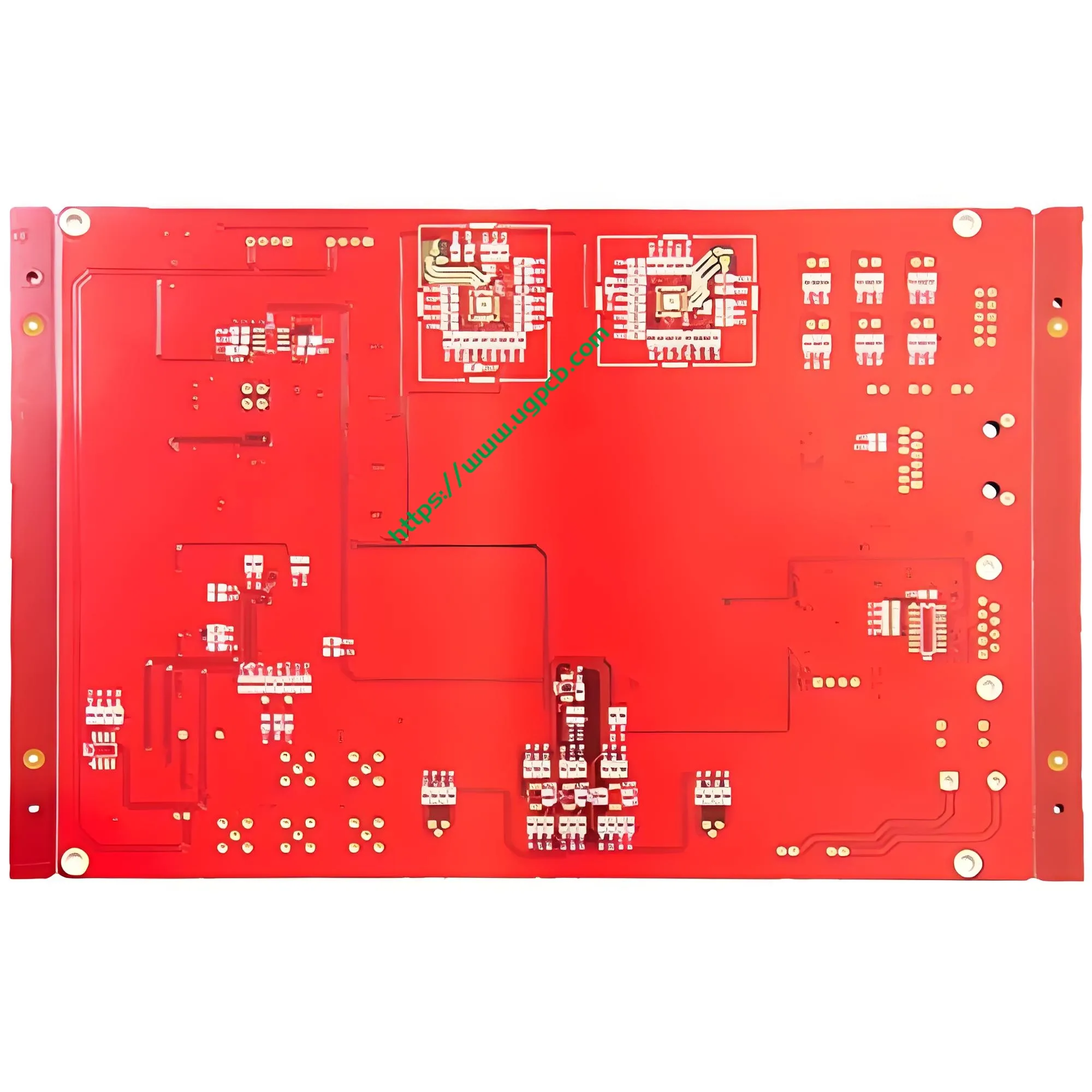
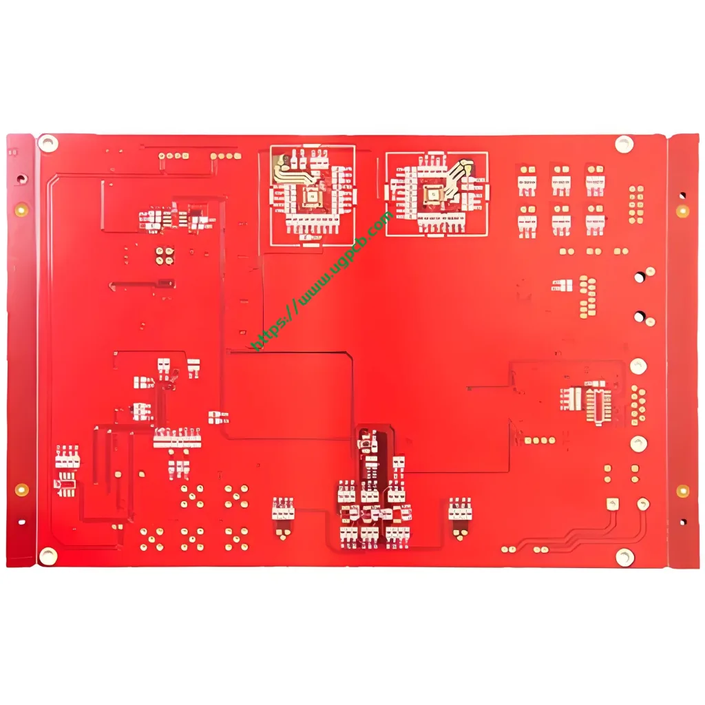
UGPCB apresenta umplaca de circuito impresso rígida de camada dupla exatamente para esse propósito. Fabricamos esta placa usando um laminado epóxi reforçado com vidro FR4 de alta qualidade. A espessura da placa mede 1,0 mm. Suas dimensões compactas são 53.68 x 37,5 mm. Adaptamos especificamente essas especificações às restrições de espaço interno dos modernos dispositivos laser portáteis e profissionais.
Esse PCB suporta ambos Luz pulsada intensa IPL e laser de diodo sistemas de depilação. Garante conexões elétricas estáveis e transmissão de sinal confiável. Um superior PCBA (Conjunto da placa de circuito impresso) constitui a base de equipamentos estéticos de alto desempenho. A UGPCB é especializada em fornecer alta confiabilidade, placas de circuito de alta precisão para fabricantes globais de dispositivos de beleza.
II. Definição do Produto: O que é uma PCB de instrumento de remoção de pêlos a laser?
UMinstrumento de depilação a laser PCB é uma placa de circuito impresso dedicada. Ele gerencia funções essenciais como distribuição de energia, controle de driver de laser, monitoramento de temperatura, e interação da interface do usuário.
Pense nisso como o sistema nervoso central do dispositivo. Ele canaliza com precisão a energia elétrica da bateria para o gerador de laser. Ele monitora simultaneamente a temperatura do sistema, ajusta os níveis de energia, e processa entradas de botão.
Tecnicamente, este produto é umfrente e verso, PCB rígida banhada através de furo. Ele usa material FR4. De acordo com IPC-6012 (Especificação de qualificação e desempenho para placas impressas rígidas), esta placa se encaixa no tipo rígido com furos chapeados. Nosso produto atendeAula 2 requisitos (Produtos eletrônicos de serviço dedicado). Esta classe é adequada para dispositivos onde a alta confiabilidade é essencial, mas não é essencial, como sistemas de depilação para uso doméstico e de salão.
III. Fundamentos de design: Precisão de Engenharia
O excelente design de PCB vai muito além da simples conectividade. Nossa equipe de engenharia se concentra em vários fatores críticos para este PCB de depilação a laser.
3.1 Projeto de isolamento e anti-interferência
Os instrumentos de depilação a laser contêm circuitos de acionamento de alta tensão e circuitos de controle de baixa tensão. Interferência eletromagnética (EMI) entre esses domínios muitas vezes causa instabilidade. UGPCB isola fisicamente loops de energia e sinal. Usamos um empilhamento de camadas racional e roteamento otimizado para mitigar interferências mútuas de forma eficaz.
3.2 Layout compacto e otimização de espaço
O 53.68 x 37,5 mm exige integração de alta densidade. Nossa equipe de design consegue uma colocação abrangente de módulos funcionais dentro deste espaço limitado. Esse roteamento denso garante excelente desempenho elétrico e permite a miniaturização do dispositivo.
3.3 Gerenciamento térmico
Os circuitos do driver do laser geram calor considerável durante a operação. O PCB atua como um caminho primário de condução de calor. FR4 oferece condutividade térmica inerente. Combinado com vazamento de cobre otimizado e colocação térmica via, nosso design dissipa o calor de forma eficiente. Essa abordagem aumenta a confiabilidade do dispositivo e prolonga a vida útil operacional.
3.4 Aderência aos Padrões de Design IPC
IPC-2221 (Padrão genérico para design de placas impressas) recomenda uma folga elétrica mínima de 0,1 mm (4 milésimos) para equipamentos em geral. Nosso design usa uma largura de linha e espaçamento de0.36mm e 0,38 mm. Esta especificação excede em muito o requisito mínimo. Ele fornece uma margem de segurança substancial para desempenho elétrico.
4. Princípio de funcionamento: Como o PCB impulsiona a emissão de laser
O princípio da depilação a laser é simples, ainda assim, o controle preciso requer uma coordenação complexa de PCB. Todo o fluxo de trabalho segue estas etapas:
Etapa 1: Entrada e gerenciamento de energia. A bateria ou adaptador fornece energia bruta. O circuito de gerenciamento de energia do PCB regula, filtros, e distribui essa energia. Ele fornece limpeza, tensão estável para todos os módulos funcionais.
Etapa 2: Controle de nível de energia. O usuário seleciona um nível de energia (comumente 5 configurações ajustáveis). O MCU (Unidade Microcontroladora) no PCB recebe este comando. Em seguida, ele envia um PWM (Modulação por largura de pulso) sinal. Este sinal aciona com precisão o circuito do driver do laser, ajustando a corrente de saída para o gerador de laser.
Etapa 3: Condução e emissão de laser. O circuito acionador converte energia elétrica em uma corrente operacional precisa para o diodo laser. Esta corrente aciona o laser para emitir o comprimento de onda específico (normalmente 808 nm ou 1064 nm).
Etapa 4: Monitoramento e proteção em tempo real. Sensores de temperatura na PCB monitoram continuamente o estado térmico do dispositivo. O MCU reduz automaticamente a energia ou desliga a saída se as temperaturas excederem os limites seguros. O PCB também lida com funções de detecção de contato com a pele e contagem de tiros. Toda essa lógica complexa funciona perfeitamente no 53.68 x placa de 37,5 mm.
V. Aplicativos primários e cenários de uso
Nós projetamos issoPCB para depilação a laser para diversas aplicações em toda a indústria estética.
| Campo de Aplicação | Caso de uso específico | Equipamento Típico |
|---|---|---|
| Cuidados de beleza em casa | Depilação pessoal | Dispositivos IPL para uso doméstico, sistemas laser domésticos |
| Salões Profissionais | Serviços estéticos comerciais | Equipamento de laser de diodo de nível profissional |
| Estética Médica | Tratamentos clínicos | Sistemas médicos de terapia a laser |
| Fabricação ODM/OEM | Produção contratada | Conjunto de PCB de dispositivo depilatório de marca |
Além disso, a lógica de design e os processos de fabricação deste PCB são adaptáveis. Eles se adaptam a outros dispositivos estéticos, incluindomáquinas de fotorejuvenescimento, removedores de pigmentação, e RF (radiofrequência) instrumentos de beleza.
VI. Classificação do Produto
Podemos classificar cientificamente este produto em múltiplas dimensões:
- Por material de substrato: PCB rígida de tecido de vidro epóxi FR4
- Por contagem de camadas: 2-camada (placa rígida dupla face padrão)
- Por acabamento superficial: CONCORDAR (Ouro de imersão em níquel eletrolítico) / Processo de folheamento a ouro
- Por classificação de inflamabilidade: UL 94 V-0 grau retardador de chama
- Por aplicação: Médico do consumidor / dispositivo estético PCB
- Por nível de desempenho IPC-6012: Aula 2 (Produtos eletrônicos de serviço dedicado)
VII. Composição de materiais: Garantia de Qualidade FR4
7.1 Laminado revestido de cobre FR4
Fabricamos este PCB usandoLaminado revestido de cobre epóxi de vidro FR4. FR4 é o substrato predominante na indústria de PCB. Consiste em tecido de fibra de vidro impregnado com resina epóxi, curado sob alto calor e pressão. Para IPC-4101 (Especificação de materiais básicos para placas impressas rígidas e multicamadas), FR4 exibe essas propriedades críticas:
- Temperatura de transição vítrea (Tg): 130–140ºC
- Constante dielétrica (Dk): 4.3–4,8 a 1 MHz
- Classificação inflamabilidade: Compatível com UL 94 V-0
- Coeficiente de Expansão Térmica (CTE): 12–18 ppm/°C
Especificamente, de acordo com IPC-4101/21, placas FR-4 padrão têm um Tg (Método TMA) variando de 110°C a 135°C. UGPCB seleciona materiais que excedem confortavelmente esta linha de base.
7.2 Folha de cobre
UGPCB se aplica35/35µm (1onças/1 onça) Folha de cobre em ambos os lados. A especificação de 1 onça representa a espessura de cobre mais amplamente utilizada. Atinge um equilíbrio ideal entre capacidade de transporte de corrente e eficiência de custos.
7.3 Máscara de solda e tinta de legenda
Aplicamos ummáscara de solda vermelha (óleo vermelho) combinado compersonagens de serigrafia branca (texto branco) . Este esquema de alto contraste oferece diversas vantagens. Facilita a inspeção óptica automatizada (AOI). Também auxilia na inspeção manual, retrabalhar, e manutenção. Além disso, a máscara protege os vestígios de cobre da oxidação, shorts, e ponte de solda durante a montagem.
VIII. Parâmetros técnicos e conformidade com padrões
8.1 Resumo dos parâmetros principais
| Parâmetro | Especificação | Observações |
|---|---|---|
| Material base | FR4 | Laminado de tecido de vidro epóxi |
| Espessura da placa | 1.0milímetros | Espessura rígida padrão |
| Contagem de camadas | 2 camadas | Roteamento frente e verso |
| Dimensões | 53.68 x 37,5 mm | Fator de forma compacto |
| Abertura Mínima | 0.33milímetros (aprox.. 13 milésimos) | Capacidade de perfuração de precisão |
| Largura da linha / Espaçamento | 0.36milímetros / 0.38milímetros (14.2/15 milésimos) | Excede os requisitos de autorização IPC-2221 |
| Espessura da folha de cobre | 35/35µm (1onças/1 onça) | Cobre pesado de dupla face |
| Acabamento superficial | CONCORDAR (Ouro de imersão em níquel eletrolítico) | Processo de banho de ouro |
| Cor da máscara de solda | Vermelho | Óleo vermelho |
| Cor da legenda | Branco | Texto branco |
8.2 Conformidade com padrões
Nosso design e fabricação de produtos seguem rigorosamente esses padrões internacionais:
- IPC-6012: Qualificação e desempenho de placas impressas rígidas
- IPC-4101/21: Especificação do material laminado FR-4
- IPC-A-600: Aceitabilidade de placas impressas
- IPC-4552: Especificação de acabamento superficial ENIG
- UL 94 V-0: Classificação mais alta de inflamabilidade para materiais plásticos
8.3 Validação de Confiabilidade
Para IPC-6012, placas rígidas devem passar por vários testes de consistência de qualidade. UGPCB realiza 100% testes elétricos (sonda voadora ou teste de fixação dedicado) em cada tabuleiro. Este processo garante integridade elétrica impecável antes do envio. Nossos conselhos passam consistentemente:
- Testes elétricos: Continuidade, resistência de isolamento, tensão suportável dielétrica
- Testes Mecânicos: Força de casca, empenamento, estabilidade dimensional
- Testes Ambientais: Estresse térmico, ciclagem de temperatura, resistência à umidade
IX. Características estruturais e características físicas
9.1 Configuração de camada dupla
Esse2-camada PCB apresenta circuitos de cobre nos lados superior e inferior do substrato do FR4.Orifícios passantes banhados (PTH) fornecer interconexão elétrica entre as camadas. Esta estrutura alcança uma alta densidade de roteamento enquanto controla os custos de fabricação. Representa o tipo de PCB mais econômico para produtos eletrônicos de consumo.
9.2 Abertura mínima 0,33 mm
A abertura mínima de 0,33 mm (13 milésimos) demonstra o UGPCBcapacidade de perfuração de precisão. IPC-6012 exige controle de tolerância rígido e espessura de revestimento adequada dentro da parede do furo. Nosso processo garante que essas especificações sejam consistentemente atendidas, garantindo confiabilidade a longo prazo das conexões revestidas.
9.3 Precisão de largura/espaçamento de linha (0.36/0.38milímetros)
A largura do traço de 0,36 mm e a folga de 0,38 mm oferecem margens substanciais de segurança elétrica. Em comparação com a linha de base do IPC-2221 de 0,1 mm, nosso design reduz diafonia e elimina riscos de curto-circuito. Este roteamento conservador, porém preciso, melhora a integridade do sinal em ambientes barulhentos e de alta potência.
9.4 Vantagens do acabamento superficial ENIG
Nós adotamosOuro de imersão em níquel eletrolítico (CONCORDAR) para tratamento de superfície, totalmente compatível com IPC-4552. Este processo de folheamento a ouro oferece benefícios distintos:
- Soldabilidade superior: A camada de ouro protege o níquel da oxidação, garantindo excelente formação de juntas de solda.
- Coplanaridade plana: ENIG fornece uma superfície excepcionalmente lisa, ideal para montagem de componentes de passo fino.
- Vida útil estendida: O revestimento resiste à oxidação, permitindo armazenamento de longo prazo sem degradação do desempenho.
- Compatibilidade de ligação de fio de alumínio: Este acabamento atende a requisitos específicos de embalagens de alta qualidade.
IPC-4552 especifica uma espessura de camada de níquel de 3–6 µm e uma espessura mínima de camada de ouro de 0,05 µm. O processo ENIG da UGPCB segue estritamente estas especificações.
X. Fluxo do Processo de Fabricação
Produzir um PCB de remoção de pêlos a laser de alta qualidade requer um rigoroso, fluxo de trabalho em várias etapas. UGPCB segue esta sequência precisa:
- Corte: Cortamos os grandes painéis revestidos de cobre FR4 em peças gerenciáveis de tamanho de produção.
- Perfuração: Máquinas de perfuração CNC crie todos os furos passantes, incluindo as aberturas de precisão de 0,33 mm.
- Deposição de cobre eletrolítico & Chapeamento de painel: Depositamos quimicamente uma fina camada de cobre dentro dos buracos. Este processo cria o barril condutor de PTH, habilitando a conexão entre camadas.
- Transferência de padrão: Nós laminamos, expor, e revelar filme fotorresistente para transferir o padrão do circuito para as superfícies de cobre.
- Gravura: A gravação química remove o cobre indesejado, deixando o padrão de circuito final com uma largura de traço precisa de 0,36 mm.
- Aplicação de máscara de solda: Aplicamos a tinta vermelha da máscara de solda. Este revestimento protege o circuito e define as almofadas de solda expostas.
- Acabamento superficial (CONCORDAR): Aplicamos as camadas de níquel eletrolítico e ouro de imersão, totalmente compatível com IPC-4552.
- Impressão de legenda: Imprimimos a legenda em serigrafia branca, marcando claramente designadores de componentes e indicadores de polaridade.
- Teste elétrico: Nós atuamos 100% sonda voadora ou testes elétricos baseados em acessórios para verificar o desempenho.
- Roteamento / Corte em V: Encaminhamos ou cortamos em V o painel de produção até o final 53.68 dimensão x 37,5 mm.
- Controle de Qualidade Final & Embalagem: Inspecionamos as placas de acordo com os critérios IPC-A-600. As placas aceitas são embaladas a vácuo para protegê-las durante o transporte.
XI. Por que escolher UGPCB para sua PCB de instrumento de remoção de pêlos a laser?
11.1 Endosso padrão oficial
UGPCB está estritamente alinhado com IPC-6012, IPC-4101, IPC-A-600, e padrões IPC-4552. Cada processo, desde a seleção do material até a inspeção final, segue benchmarks verificáveis do setor. Nossa qualidade resiste às mais rigorosas auditorias.
11.2 Fabricação de precisão avançada
Nossa capacidade de produzir aberturas mínimas de 0,33 mm e largura/espaçamento de linha de 0,36/0,38 mm destaca nossa experiência técnica. Possuímos a precisão necessária para aplicações exigentes de depilação a laser.
11.3 Profunda experiência na indústria estética
UGPCB possui amplo conhecimento de domínio em PCBs de dispositivos estéticos. Compreendemos profundamente os requisitos exclusivos do laser, IPL, e equipamento de fotorejuvenescimento - incluindo isolamento de alta tensão, Gerenciamento térmico, Supressão EMI, e restrições estritas de confiabilidade.
11.4 UL 94 V-0 Garantia de inflamabilidade
Nós fornecemos materiais que atendem aosUL 94 V-0 classificação - a mais alta classificação retardante de chama. De acordo com UL94, V-0 requer que cada amostra queime por ≤10 segundos após cada aplicação de chama. O tempo total de queima para um conjunto de cinco amostras deve ser ≤50 segundos. Além disso, nenhuma gota de chama pode inflamar o algodão subjacente. Isto garante a máxima segurança, mesmo em condições operacionais anormais.

XII. Contate-nos para obter sua solução de PCB personalizada
UGPCB fornece alta qualidadeinstrumento de depilação a laser PCBs e chave na mãoPCBA serviços para fabricantes globais de dispositivos estéticos. Somos o seu parceiro ideal se você estiver:
- Um engenheiro de design desenvolvendo sistemas de depilação de última geração.
- Um gerente de compras em busca de um fornecedor confiável de PCB.
- Um gerente de produto que exige soluções PCBA personalizadas.
- Uma equipe empreendedora entrando no mercado de dispositivos de beleza.
Contate-nos hoje para obter uma folha de dados do produto, uma cotação competitiva, ou uma consulta técnica gratuita!
📧 E-mail: [info@ugpcb.com]
🌐 Site: [www.ugpcb.com]
📞 Telefone: [+86-135 4412 8719]
XIII. Declaração da fonte de dados
Os padrões técnicos e dados de desempenho citados neste artigo são originários das seguintes instituições autorizadas:
- IPC (Associação conectando indústrias eletrônicas) — Os padrões referenciados incluem IPC-6012 (Especificação de qualificação e desempenho para placas impressas rígidas), IPC-4101 (Especificação de materiais básicos para placas impressas rígidas e multicamadas), IPC-A-600 (Aceitabilidade de placas impressas), IPC-2221 (Padrão genérico para design de placas impressas), e IPC-4552 (Especificação para níquel eletrolítico/ouro de imersão (CONCORDAR) Chapeamento para placas impressas).
- UL (Laboratórios de subscritores) - UL 94 (Norma para testes de inflamabilidade de materiais plásticos para peças em dispositivos e eletrodomésticos) V-0 Classificação de chama.
- Publicações Técnicas da Indústria — Parâmetros de propriedade de material FR4 (Tg 130–140°C, Dk 4,3–4,8 @ 1 MHz, CTE 12–18 ppm/°C) são valores de referência reconhecidos de folhas de dados de materiais compósitos e diretrizes IPC-4101.













