
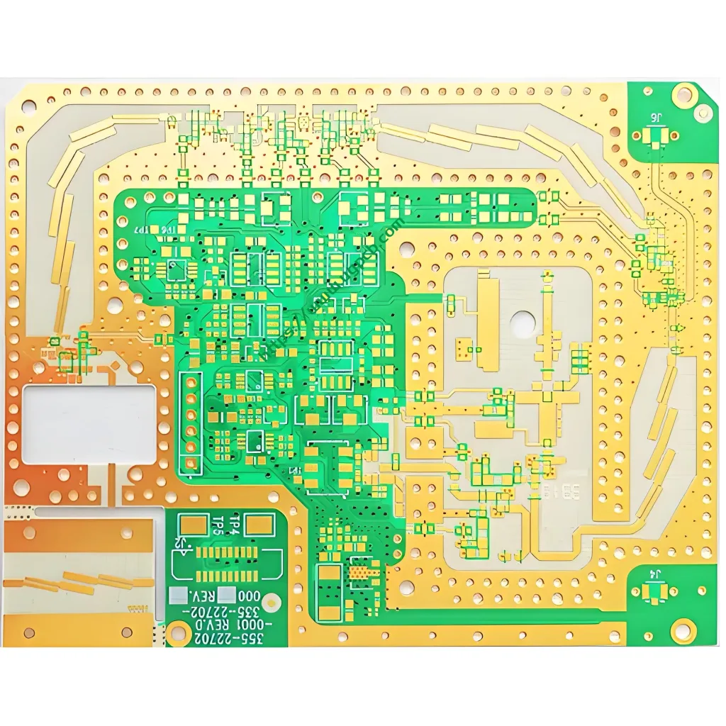
1. Product Overview: What is Rogers 4003 PCB?
The Rogers 4003 PCB is a high-performance printed circuit board manufactured using Rogers Corporation’s RO4003C™ laminate material. This product belongs to the RO4000® series hydrocarbon-ceramic composite material family. Manufacturers design this PCB specifically for high-frequency RF circuits, microwave circuits, and high-speed digital systems. It offers industry-leading low dielectric constant, low loss properties, and excellent thermal stability.
Rogers Corporation developed the patented RO4003C™ material technology. This material is a hydrocarbon resin system enhanced with ceramic filler particles and reinforced with woven glass fabric. The electrical performance of this material system matches traditional PTFE/woven glass materials. Cu toate acestea, the processing method works with standard epoxy/woven glass (FR-4) Producția de PCB proceselor. This eliminates the need for special via pretreatment or sodium etching, which significantly reduces manufacturing costs.
RO4003C laminate complies with IPC-4103 standard, Slash Sheet /10 clause. This classification covers laminate base material specifications for high-speed/high-frequency applications. Within the IPC standard system, IPC-4103 applies specifically to high-speed/high-frequency copper-clad laminate base material specifications. IPC-4104 covers interconectare de înaltă densitate (HDI) and microvia material requirements.
This product uses a stackup structure of RO4003C (miez) + RO4450F (prepreg/bonding layer). This forms a high-reliability multilayer board configuration. It works especially well for high-density interconnect high-performance RF and microwave modules.
2. Product Definition and Core Specifications
UGPCB’s Rogers 4003 PCB uses the following precise configuration parameters:
| Parametru | Caietul de sarcini |
|---|---|
| Material Type | Rogers RO4003C + RO4450F Bondply |
| Constanta dielectrică (DK) | 3.38 ± 0.05 @10 GHz |
| Factor de disipare (Df / tan δ) | 0.0027 @10 GHz |
| Core Thickness | 0.508mm (20mil) |
| Finished Board Thickness | 2.0mm |
| Base Copper Thickness | 17μm (0.5 Oz) |
| Finished Copper Thickness | 1 Oz (35μm) |
| Surface Finish | Aur de imersiune (De acord) |
| Solder Mask Color | Verde / Alb |
| Min min / Spaţiu | 6mil / 6mil |
| Glass Style | 1080 / 1674 |
| Flame Rating | Ul 94 V-0 (when paired with RO4835/RO4350B) |
| Conductivitate termică | 0.71 W/m·K |
Test Method Reference: IPC-TM-650 2.5.5.5 (Stripline method), measured @10GHz/23°C.
3. Ghid de proiectare
Engineers must focus on these key points when designing Rogers 4003 PCB:
Controlul impedanței Proiecta: RO4003C has a tightly controlled dielectric constant of Dk=3.38±0.05 at 10 GHz. This tolerance ensures impedance consistency within ±5%, greatly improving RF matching network and transmission line design accuracy.
Copper Thickness Selection: This configuration starts with 17μm (0.5 Oz) base copper thickness. The finished copper thickness reaches 1 Oz (35μm) through electroplating. Matching Z-axis copper and dielectric CTE is crucial for multilayer board via reliability.
Line/Space Capability: The minimum trace width and spacing of 6mil/6mil is a baseline for signal integrity and design for manufacturability (DFM). High-density interconnect designs can go further to 4mil/4mil depending on equipment capabilities.
Multilayer Configuration: Using RO4450F as the bonding material between core layers provides better flow than RO4450B, making it the preferred choice for new designs. RO4450F has a Z-axis CTE range of 43–60 ppm/°C, ensuring plated through-hole reliability under thermal cycling.
Solder Mask and Surface Finish: Use high-quality photoimageable solder mask ink with ENIG surface finish. This provides solderability protection, oxidation resistance, and prevents copper surface contamination.
4. Working Principle and Electrical Mechanism
The high-frequency working principle of Rogers 4003 PCB relies on the material’s low dielectric constant (DK) and low dissipation factor (Df / tan δ).
Signal Propagation Speed (Vp) Calculation:
Vp = c / √Dk
Unde:
-
c = speed of light ≈ 3×10⁸ m/s
-
Dk = dielectric constant = 3.38
-
Vp ≈ c / √3.38 ≈ c / 1.838 ≈ 1.63×10⁸ m/s ≈ 163 mm/ns
Compared to typical FR-4 material (Dk ≈ 4.2–4.8, according to IPC-4101E, @1MHz Dk range 4.2-4.8), RO4003C reduces the dielectric constant by approximately 20%–30%. This significantly increases signal transmission speed and reduces propagation delay.
Signal Loss Mechanism:
Insertion loss (IL) consists of dielectric loss and conductor loss:
-
Dielectric loss relates to Dk and Df: αd ≈ k·f·√Dk·Df
-
RO4003C has a very low loss factor of Df=0.0027 at 10 GHz, far lower than the typical FR-4 value (≈0.018–0.020)
-
This superior loss performance ensures high signal fidelity in the GHz frequency range
Thermal Management Performance:
Thermal conductivity k = 0.71 W/m·K, better than traditional FR-4 (approx. 0.25 W/m·K). This helps power amplifiers and RF front-end modules dissipate heat effectively.
5. Product Scientific Classification
Based on international industry standards and material properties, this product fits into the following scientific classification categories:
| Classification Dimension | Categorie |
|---|---|
| By IPC Standard | IPC-4103 High-Speed/High-Frequency Base Material (Slash Sheet /10) |
| By Material System | Hydrocarbon Resin + Ceramic Filler + Woven Glass Fabric Composite |
| By Frequency Applicability | High-Frequency RF/Microwave PCB, Usable Frequency Range DC–30 GHz |
| By Structural Type | Multilayer Laminated PCB (RO4003C + RO4450F Bondply) |
| By Surface Finish | Aur de imersiune (De acord) PCB |
| By Flame Rating | Non-UL 94 V-0 Aplicații (Select RO4835/RO4350B for flammability rating) |
| By Processing Compatibility | FR-4 Process-Compatible High-Frequency PCB |
| By Environmental Compliance | Halogen-Free / RoHS and REACH Compliant |
This classification system provides accurate identification for supply chain management, quality evaluation, and application selection.
6. Material Analysis
Core Layer – RO4003C™ Material Properties:
RO4003C is a hydrocarbon resin and ceramic filler composite reinforced with woven glass fabric. The material offers these key properties:
-
Dielectric Constant Dk: 3.38 ± 0.05 (@10GHz)
-
Dissipation Factor Df: 0.0027 (@10GHz)
-
Glass Transition Temperature Tg: >280° C.
-
Thermal Decomposition Temperature Td: 425° C.
-
Z-axis CTE: 46 PPM/° C.
-
Thermal Conductivity K: 0.71 W/m·K
-
Rezistivitatea volumului: 1.7×10¹⁰ MΩ·cm
-
Rezistivitatea suprafeței: 4.2×10⁹ MΩ
Bonding Layer – RO4450F™ Bondply:
RO4450F belongs to the RO4400™ series prepreg. This material works specifically for multilayer board lamination and offers the following features:
-
Prepreg grade based on RO4000 series cores
-
Fully compatible with RO4003C, RO4350B, and RO4835
-
Z-axis CTE: 43–60 ppm/°C
-
CAF-resistant high-reliability plated through-holes
-
Supports sequential lamination
-
Lead-free process compatible with UL 94 V-0 rating de flacără
Folie de cupru:
The starting copper foil thickness is 17μm (0.5 Oz). The final thickness reaches 1 Oz (35μm) through electroplating. ENIG surface finish provides excellent solderability and oxidation protection.
7. Performance Summary
Here is a summary of the electrical, termic, and mechanical performance of Rogers 4003 PCB:
| Performanţă | Parametru | Valoare | Test Method |
|---|---|---|---|
| Electric | DK | 3.38 ± 0.05 @10GHz | IPC-TM-650 2.5.5.5 |
| Df | 0.0027 @10GHz | IPC-TM-650 2.5.5.5 | |
| Dk Temperature Coefficient | +40 PPM/° C. | IPC-TM-650 2.5.5.5 | |
| Rezistivitatea volumului | 1.7×10¹⁰ MΩ·cm | IPC-TM-650 2.5.17.1 | |
| Rezistivitatea suprafeței | 4.2×10⁹ MΩ·cm | IPC-TM-650 2.5.17.1 | |
| Breakdown Voltage | 31.2 kV/mm (780 V/mil) | IPC-TM-650 2.5.6.2 | |
| Thermal | TG | >280° C. | IPC-TM-650 2.4.25 |
| TD | 425° C. | ASTM D3850 | |
| Conductivitate termică | 0.71 W/m·K | ASTM E1461 | |
| Z-axis CTE | 46 PPM/° C. | IPC-TM-650 2.4.41 | |
| Mecanic | Tensile Modulus | 26,889 Mpa | ASTM D638 |
| Tensile Strength | 141 Mpa | ASTM D638 | |
| Fiabilitate | Moisture Absorption | ≤0.06% | IPC-TM-650 2.6.2 |
Data Source: All electrical performance parameters comply with IPC-TM-650 standard test methods.
8. Structure Analysis
This PCB uses the following standard stackup structure:
-
External Copper Foil: ENIG surface finish (1 oz finished copper)
-
Strat de masca de lipit: Green/White photoimageable solder mask ink
-
Stratul de bază: RO4003C, thickness 0.508mm, base copper 17μm
-
Bonding Layer (Bondply): RO4450F prepreg (typical thickness 0.102mm / 4mil)
-
Internal Copper Foil: ENIG or OSP, base copper 17μm
This design achieves a total finished board thickness of 2.0mm. It meets high mechanical strength requirements and allows multilayer high-density routing. The flow properties of RO4450F ensure filling of copper area gaps, producing a uniform laminated structure.
9. Product Features
-
Tight Dk Control: The dielectric constant has an ultra-narrow tolerance of 3.38 ± 0.05, ensuring consistent impedance matching in RF circuits.
-
Very Low High-Frequency Loss: Df of 0.0027 la 10 GHz makes this PCB ideal for low noise amplifiers, filtre, and power dividers.
-
FR-4 Process Compatibility: Standard FR-4 production equipment and processes work, avoiding special sodium etching or plasma treatment needed for PTFE-based materials. This lowers overall manufacturing costs.
-
Ul 94 V-0 Compatibilitate: RO4003C is a bromine-free material and does not directly meet UL 94 V-0. Pair it with RO4835 or RO4350B to achieve UL 94 V-0 rating de flacără.
-
High Heat Resistance: TG >280° C., Td of 425°C, supporting lead-free soldering processes such as 260°C reflow.
-
Excellent Dimensional Stability: Z-axis CTE matches copper (46 PPM/° C.), ensuring multilayer board reliability under multiple thermal cycles.
-
CAF Resistance: RO4450F provides excellent resistance to conductive anodic filament formation.
-
Environmentally Friendly: Bromine-free flame retardants, meeting RoHS and REACH environmental regulations.
-
Hybrid Lamination Compatibility: Compatible with hybrid multilayer lamination using FR-4 and other Rogers core materials. This enables cost-effective high-density interconnect designs.
10. Manufacturing Process
UGPCB uses a standardized manufacturing process for Rogers 4003 PCB, including these key steps:
-
Incoming Material Inspection: Test thickness, DK, Df, and other properties of RO4003C, RO4450F prepreg, și folie de cupru. Ensure batch consistency.
-
Inner Layer Circuit Formation: Use high-precision photoplotting or direct imaging equipment to form inner layer circuits. Control minimum line/space at 6mil/6mil.
-
AOI Inspection: Perform full automated optical inspection for circuit defects.
-
Pre-Lamination Treatment: Include copper surface roughening and cleaning.
-
Multilayer Lamination: Control lamination temperature, pressure, and time precisely. Follow Rogers recommended lamination profile of 175°C–215°C, 200–300 PSI.
-
Foraj: Use carbide or diamond-coated drill bits. Ensure hole position accuracy and hole wall quality.
-
Desmear: Use plasma or chemical cleaning to remove residue from hole walls. This ensures good plating adhesion.
-
Electroless Copper Deposition and Panel Plating: Electroless copper deposition followed by panel plating to reach the required 1 oz copper thickness.
-
Outer Layer Circuit Formation: Use tin protection followed by etching to form the outer layer conductive pattern.
-
Solder Mask Printing: Apply green or white photoimageable solder mask layer.
-
Surface Finish: Aur de imersiune (De acord) — nickel barrier layer plus gold top layer for protection.
-
Routing and V-CUT: Use CNC milling for board outline profiling.
-
Testare electrică: Perform 100% flying probe or fixture testing to ensure open/short circuit insulation reliability.
-
Final Quality Control (FQC): Perform visual and dimensional inspection.
-
Packaging and Shipping: Use vacuum packaging with antistatic protection.
Key Process Guarantee: Rogers 4003 PCB fully complies with IPC-A-600 Class 3 acceptance criteria. Each shipment includes a 100% electrical test report.
11. Application Scenarios and Typical Uses
The global Rogers PCB market is expected to grow at a compound annual growth rate (CAGR) de 5.4% between 2024 şi 2030. With the rapid growth of 5G communications, the Internet of Things (Iot), radar auto, and aerospace electronics applications, Rogers 4003 PCB has become a mainstream high-frequency material with broad application prospects.
Typical application scenarios for Rogers 4003 PCB include:
11.1 Wireless Communications and Infrastructure
-
5G base station (Sub-6GHz) RF front-end modules
-
Antenna matching networks and filters
-
RF power amplifiers
-
Point-to-point microwave backhaul systems
11.2 Automotive Radar and ADAS Systems
-
77 GHz radar sensors
-
Advanced driver assistance systems (ADAS)
-
Vehicle millimeter-wave antenna modules
11.3 Aerospace and Military Electronics
-
Satellite communication LNB modules
-
Air traffic control radar
-
Military phased array radar components
-
Low Earth orbit (LEU) satellite payloads
11.4 Internet of Things (Iot) and Sensor Networks
-
Smart home gateways
-
RFID readers and sensor tags
-
High-reliability outdoor communication nodes
11.5 High-Speed Digital Systems
-
Optical module PCB (40G/100G/400G)
-
High-speed signal backplanes
-
Data center servers
Applicable Frequency Range: The recommended operating frequency range is DC to 30 GHz, where performance is excellent. Even at higher frequencies, this PCB can still provide stable signals in some applications.
12. Why Choose UGPCB for Rogers 4003 PCB?
✅ Genuine Material Guarantee: All RO4003C and RO4450F materials come from Rogers official authorized channels. Each shipment includes the original factory inspection report.
✅ Advanced Manufacturing Equipment: Our facility includes German and Japanese imported lamination, foraj, placare, and AOI inspection equipment. This supports fine line/space production.
✅ Strict IPC Standards: We manufacture according to IPC-4103 and IPC-6012 Class 3 performance specifications. Every batch undergoes 100% electrical testing.
✅ Efficient Technical Support: Our dedicated engineering team supports impedance optimization, design de stivuire, and DFM review.
✅ Fast Response Quotation: We provide technical evaluation and quotation within 24 hours of receiving Gerber/BOM files.
✅ Global Delivery Capability: Standard lead times of 5–8 business days for production plus shipping. We meet project needs worldwide.
13. Request a Quote Today!
📌 Three simple steps to receive a professional response:
-
Send your Gerber files, Bill of Materials (BOM), stackup, or design requirements to sales@ugpcb.com or contact us via WhatsApp/WeChat for an online consultation.
-
Our engineering team will perform a DFM review and provide an accurate quote (including tooling/fixture costs) within 24 ore.
-
After order confirmation, we will schedule production and provide regular progress updates. We will deliver on time.
🛜 UGPCB has its own efficient production base, a strict quality management system, and deep technical support experience for high-frequency applications. Whether you need prototype samples or volume production, we are committed to providing highly stable, highly consistent Rogers 4003 Produse PCB.
We support small-batch trial production and volume production. We offer multiple surface finish options including ENIG, Immersion Tin, și OSP.
📞 +86-755-1234-5678 | 📧 sales@ugpcb.com
👉 Faceți clic pe “Request a Quote” button below to upload your design files and receive a customized solution!


