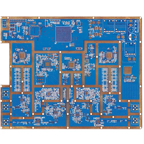
1. Обзор продукта: Что такое высокочастотная гибридная печатная плата?
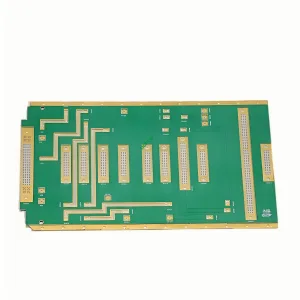
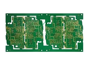
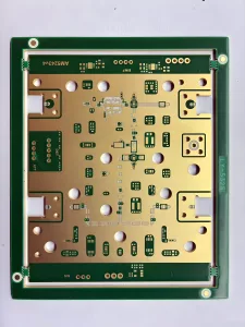
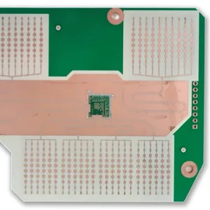
А высокочастотная гибридная печатная плата объединяет высокочастотные ламинаты Rogers RO4350B со стандартными материалами FR4 в одном многослойная плата благодаря прецизионному ламинированию.
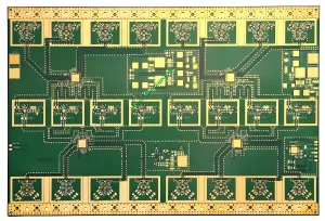
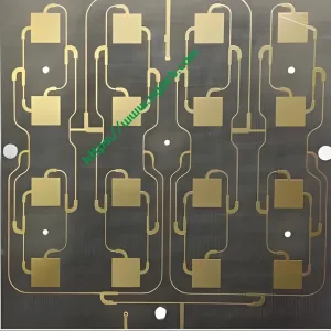
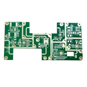
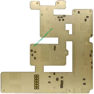
УГКПБ предлагает12-многослойная высокочастотная гибридная печатная плата построен на базе Rogers RO4350B и FR4. Толщина готовой платы составляет 1,6 мм с готовой медью 1 унция.. Характеристическое сопротивление точно контролируется на уровне 50 Ом.. Эта плата предназначена для приложений ВЧ/СВЧ и смешанных сигналов, требующих как высокочастотной производительности, так и экономической эффективности..
Почему стоит выбрать гибридную конструкцию? В базовых станциях 5G, Автомобильный радар, и высокоскоростные модули связи, ВЧ-схемам необходимы материалы Rogers с низкими потерями для обеспечения целостности сигнала.. Цифровые схемы управления, управление питанием, и интерфейсы прекрасно работают со стандартом FR4 при гораздо меньших затратах.. Полная доска Роджерса стоит 3 к 8 раз больше, чем FR4. Полноценная плата FR4 не может соответствовать требованиям к радиочастотным характеристикам.. The высокочастотная гибридная печатная плата обеспечивает оптимальный баланс между производительностью и стоимостью.
2. Классификация продукции и соответствие стандартам
2.1 Классификация по сочетанию материалов
Этот продукт представляет собойпечатная плата из гибридного ламината — объединение Rogers RO4350B (высокочастотные слои) с FR4 (цифровые/силовые уровни) за счет прецизионного прессования. Под МПК-4101, Rogers RO4350B — это ламинат, армированный стекловолокном и наполненный углеводородами.. FR4 — огнестойкий эпоксидный тканый стеклоткань, плакированный медью..
2.2 Классификация по классу производительности IPC-6012
Для МПК-6012, это правление встречаетсяСорт 2 (электронные продукты для специального обслуживания) иСорт 3 (высоконадежное электронное оборудование) требования.
2.3 Классификация по диапазону частот
ЭтоПлата радиочастотной/микроволновой частоты. Слой Rogers RO4350B поддерживает стабильную диэлектрическую проницаемость 3,48±0,05 на частоте 10 ГГц., подходит для частот от 500 МГц до миллиметровых волн.
3. Основные материалы и ключевые параметры производительности
3.1 Rogers RO4350B – «золотой стандарт» для высокочастотных слоев
Роджерс RO4350B представляет собой запатентованную систему углеводородных смол с керамическим наполнителем., армированный стеклотканью. Ключевые преимущества включают в себя:
- Диэлектрическая проницаемость (Дк): 3.48 ± 0.05 @ 10 ГГц (значение процесса), 3.66 (расчетная стоимость). FR4 обычно имеет ±5% 10% Дк вариант. RO4350B обеспечивает допуск только ±1,4%., обеспечение прочной основы для точного контроля импеданса.
- Коэффициент рассеяния (Дф): 0.0037 @ 10 ГГц – значительно ниже, чем FR4, обеспечение передачи высокочастотного сигнала с низкими потерями.
- Теплопроводность: 0.69 Вт/м·К при 50°C (АСТМ Д5470).
- Объемный удельное сопротивление: 1.2×10¹⁰ МОм·см (ИПК-ТМ-650 2.5.17.1).
- Рейтинг огнестойкости: UL 94 В-0.
3.2 FR4 – экономичный выбор для цифровых и силовых уровней
ФР4 представляет собой стандартный огнестойкий ламинат из стеклоткани с эпоксидной смолой.. Он предлагает низкую стоимость, зрелая обработка, и высокая механическая прочность. Это хорошо работает для цифровых схем, Распределение энергии, и грунтовые слои.
3.3 12-Структура гибридного стека слоев
В этом продукте используется12-гибридный стек слоев. Во внешних слоях и критических слоях радиочастотного сигнала используются ядра Rogers RO4350B.. Внутренние слои используют ядра FR4 для питания., земля, и низкоскоростные цифровые сигналы. Общая толщина платы составляет 1,6 мм.. Толщина готовой меди составляет 1 унция. (35мкм).
3.4 Сводка ключевых параметров производительности
| Параметр | Спецификация | Тестовый/эталонный стандарт |
|---|---|---|
| Ламинат | Роджерс RO4350B + ФР4 | - |
| Количество слоев | 12 слои | - |
| Толщина готовой доски | 1.6мм | МПК-6012 |
| Толщина готовой меди | 1ОЗ (35мкм) | МПК-6012 |
| Характерный импеданс | 50Ой | МПК-2141 / МПК-2251 |
| Диэлектрическая толщина | 0.508мм | - |
| Диэлектрическая проницаемость (Дк) | 3.48 ± 0.05 @ 10 ГГц | Техническое описание Роджерса RO4350B |
| Теплопроводность | 0.69 Вт/м·К при 50°C | АСТМ Д5470 |
| Рейтинг огнестойкости | UL 94 В-0 | UL 94 |
| Объемный удельное сопротивление | 1.2×10¹⁰ МОм·см | ИПК-ТМ-650 2.5.17.1 |
4. Соображения дизайна: Четыре основных принципа создания высокочастотных гибридных печатных плат
4.1 Контроль импеданса – достижение цели в 50 Ом
Контроль импеданса занимает центральное место в Высокочастотная печатная плата дизайн. Стандарт 50 Ом является наиболее широко используемым сопротивлением в радиочастотных системах.. Этот продукт поддерживает сопротивление на уровне 50Ой для обеспечения максимальной передачи мощности и минимального отражения сигнала.
Точность импеданса зависит от толщины диэлектрика., диэлектрическая проницаемость, и ширина трассы. Допуск ±1,4% Dk RO4350B дает явное преимущество по сравнению с ±5% у FR4. 10% вариация. Критическое замечание: потому что RO4350B имеет более низкий Dk, Ширина трасс сигнала на слоях Роджерса должна составлять примерно 10% к 15% шире, чем слои FR4 для конструкций с сопротивлением 50 Ом. Кроме того, Изменение толщины диэлектрика на ±0,5 мил может привести к сдвигу импеданса примерно на ±2 Ом на микрополосковой линии Роджерса толщиной 10 мил, что делает необходимым точный контроль толщины..
4.2 Проектирование стека – баланс производительности и стоимости
Конструкция стека влияет на целостность сигнала, целостность власти, EMC performance, и сложность управления импедансом. Этот 12-уровневый стек следует этим принципам.:
- Слои радиочастотного сигнала размещаются на внешних слоях Rogers RO4350B с использованием микрополосковых структур для минимизации потерь при передаче..
- Земляной и силовой слои размещаются на слоях FR4, обеспечение стабильных опорных плоскостей.
- Симметрия слоев поддерживает механический баланс для предотвращения деформации.
- Совместимость материалов – RO4350B можно обрабатывать теми же методами, что и FR4., исключение необходимости специальной обработки отверстий, необходимой для материалов на основе ПТФЭ.
4.3 Управление температурой – 0.69 Тепловыделение Вт/м·К
Этот продукт достигает 0.69 W/m · k теплопроводность. В печатная плата тепловое управление, теплопроводность к (W/m · k) измеряет, насколько эффективно материал передает тепло. RO4350B 0.69 Вт/м·К значительно превосходит стандарт FR4 (примерно 0.25 к 0.3 W/m · k), обеспечение более эффективного отвода тепла от мощных радиочастотных устройств.
4.4 Стабильность размеров – низкий КТР обеспечивает надежность
Коэффициент теплового расширения RO4350B по оси Z (КТР) является 32 ppm/° C. (-55от °С до 288 °С). Это близко соответствует КТР меди. (примерно 17 ppm/° C.), обеспечение металлизированного сквозного отверстия (ПТХ) надежность при термоциклировании. Значения CTE по осям X и Y 10 ppm/°C и 12 ppm/°C соответственно. Температура стеклования (Тг) превышает 280°С, поддержание стабильных характеристик расширения при всех температурах обработки.
5. Принцип работы: Как передаются высокочастотные сигналы в гибридной печатной плате?
В высокочастотных цепях, сигналы распространяются как электромагнитные волны, а не как простые логические уровни «0» и «1».. Theвысокочастотная гибридная печатная плата действует через несколько механизмов:
Передача сигнала: Высокочастотные сигналы распространяются по микрополосковым или полосковым структурам на слое RO4350B.. Низкий Dk RO4350B (3.48) и низкий Df (0.0037) обеспечить распространение сигналов с минимальными вносимыми потерями.
Сопоставление импеданса: Точный контроль ширины трассы, Диэлектрическая толщина, и диэлектрическая проницаемость устанавливает характеристическое сопротивление на уровне 50 Ом.. Это соответствует источнику, линия передачи, и нагрузка – максимальная передача мощности и минимизация отражения сигнала.
Межслойное соединение: Слои высокочастотных сигналов (Роджерс) подключение к цифровым/силовым уровням (ФР4) через металлизированные сквозные отверстия (ПТХ). Низкий КТР RO4350B по оси Z (32 ppm/° C.) обеспечивает надежность PTH во время термоциклирования.
Тепловое управление: Тепло от мощных радиочастотных устройств проходит через слой RO4350B. (0.69 W/m · k) к слоям FR4 и внешним конструкциям рассеивания тепла, поддержание устройств в пределах безопасных рабочих температур.
6. Производственный процесс: От материалов к готовой 12-слойной гибридной плате
6.1 Входной контроль материалов
Осмотрите ядра Rogers RO4350B и FR4.. Проверьте диэлектрическую проницаемость, толщина, качество медной фольги, и другие параметры соответствуют требованиям IPC-4101 и спецификации Rogers..
6.2 Изготовление схемы внутреннего слоя
Перенос шаблона технологической схемы, травление, и проверка AOI на внутренних слоях FR4 (для питания и земли).
6.3 Обработка коричневым оксидом
Нанесите коричневую оксидную обработку на медные поверхности внутреннего слоя для улучшения адгезии слоя..
6.4 Укладка и ламинирование
Это самый ответственный шаг вгибридная печатная плата Производство:
- Ядра стека Роджерса, Ядра FR4, и препрег в соответствии с разработанной 12-слойной структурой.
- Используйте ступенчатое ламинирование для предотвращения напряжений и искажений размеров, вызванных различиями КТР между Rogers и FR4..
- Оптимизация выбора препрега (например, препрег с низкой текучестью) и параметры ламинирования для минимизации межслоевых напряжений.
6.5 Сверление и обезжиривание
Выполнение механического и лазерного сверления. (для глухих/скрытых переходных отверстий при необходимости). Далее следует обезжиривание и подготовка к металлизации отверстий..
6.6 Металлизация и покрытие отверстий
Примените химическое осаждение меди и электролитическое меднение для достижения толщины 1 унции. (35мкм) толщина готовой меди.
6.7 Изготовление схемы внешнего слоя
Создайте трассировки радиочастотного сигнала на внешних слоях Роджерса. Строго контролируйте ширину трасс, чтобы обеспечить точность импеданса 50 Ом..
6.8 Паяльная маска и обработка поверхности
Нанесите чернила для паяльной маски и обработайте поверхность. (например, СОГЛАШАТЬСЯ) для обеспечения паяемости и стойкости к окислению.
6.9 Электрические испытания и окончательная проверка
Выполнять 100% электрические испытания (включая проверку импеданса и проверку целостности). Провести визуальный осмотр, измерение размеров, и выборка надежности.
7. Преимущества производительности: Почему стоит выбрать 12-слойную высокочастотную гибридную печатную плату UGPCB?
7.1 Превосходные высокочастотные характеристики
RO4350B обеспечивает Dk = 3,48±0,05 при 10 ГГц и Df = 0.0037 @ 10 ГГц. Эти свойства обеспечивают низкие потери, передача сигнала с низкой дисперсией от 500 МГц до частот миллиметрового диапазона.
7.2 Точный контроль импеданса 50 Ом
Допуск ±1,4% Dk, в сочетании с точным контролем толщины диэлектрика, обеспечивает высокоточное определение характеристического сопротивления 50 Ом, что соответствует требованиям согласования импеданса радиочастотных систем..
7.3 Отличное соотношение цены и качества
По сравнению с полным решением Роджерса, аГибридное решение Rogers-FR4 экономит примерно 60% к 70% в материальных затратах, обеспечивая при этом значительно лучшие радиочастотные характеристики, чем полная конструкция FR4.
7.4 Надежные механические и термические характеристики
- UL 94 В-0 рейтинг огнестойкости
- КТР по оси Z всего 32 ppm/° C.
- Тс > 280°С
- Теплопроводность 0.69 W/m · k
7.5 Совместимость с обработкой FR4
RO4350B можно обрабатывать теми же методами, что и стандартный FR4.. Никакой специальной обработки или процедур обработки не требуется – снижение производственных затрат и сокращение времени выполнения заказов..
8. Типичные приложения
8.1 5Базовые станции связи G
Антенные решетки и РЧ-интерфейсы (усилители мощности, малошумящие усилители) требуются слои RO4350B для радиочастотных соединений с низкими потерями. Процессоры основной полосы частот и цифровые интерфейсы могут быть размещены на уровнях FR4..
8.2 Автомобильный радар миллиметрового диапазона (77ГГц)
В питающих сетях между передающими/приемными антеннами и микросхемами приемопередатчиков используются материалы Rogers для точной согласованности фазы.. Радарные контроллеры и интерфейсы CAN-шины используют уровни FR4..
8.3 Спутниковая связь и микроволновая двухточечная передача
Приложения включают антенны базовых станций сотовой связи и усилители мощности., микроволновая печь «точка-точка» (P2p) ссылки, и спутниковый малошумящий блок прямого подключения к дому (LNB) понижающие преобразователи.
8.4 Высокоскоростные оптические модули и проводная связь
В платах драйверов оптических модулей 400G, высокоскоростные дифференциальные пары SerDes (≥56 Гбит/с PAM4) требуются подложки с низкими потерями для поддержания качества глазковой диаграммы. Логика FPGA и память DDR могут использовать FR4..
8.5 RFID и беспроводное зондирование
Приложения включают RFID-метки, беспроводные системы сбора данных, беспроводные пульты дистанционного управления, и телеметрические системы.
9. Почему выбирают UGPCB?
UGPCB имеет обширный опыт в области высокочастотных свойств материалов и гибридной обработки, включая управление процессом., Медное покрытие, схемы ламинации, Допуски радиочастотных трасс, и контроль параметров импеданса. Мы обязуемся:
- ✅ 100% электрические испытания (включая тестирование импеданса)
- ✅ Строгое соответствие стандартам IPC-6012 и IPC-4101.
- ✅ Полная прослеживаемость качества процесса
- ✅ Профессиональная команда инженеров, предоставляющая DFM (Дизайн для производства) поддерживать

10. Запросите сейчас – получите индивидуальное решение
UGPCB12-Layer Rogers RO4350B+FR4 высокочастотная гибридная печатная плата ваше оптимальное решение для связи 5G, Автомобильный радар, спутниковая связь, и высокоскоростные оптические модули – баланс производительности и стоимости.
📧Отправьте запрос сейчас. Наша команда инженеров радиочастотных печатных плат ответит в течение 24 часы с:
- Индивидуальные предложения по проектированию стека
- Точные расчеты управления импедансом 50 Ом
- Конкурентные оптовые цены
- Рекомендации по оптимизации технологичности DFM
Сделайте UGPCB своим надежным партнером в проектах высокочастотных гибридных печатных плат.!