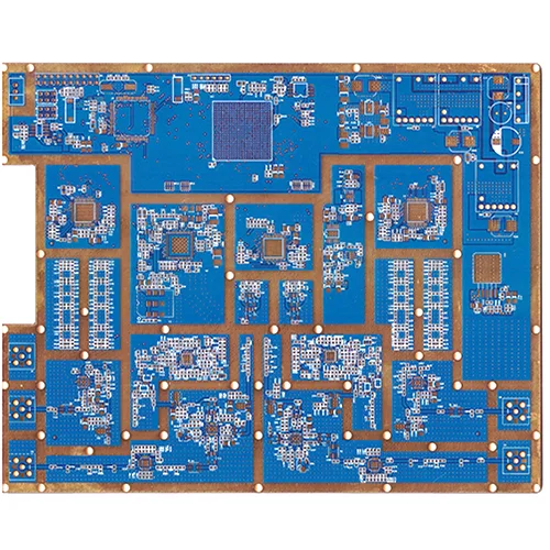
1. Produktübersicht: Was ist eine Hochfrequenz-Hybrid-Leiterplatte??
A Hochfrequenz-Hybrid-Leiterplatte integriert Rogers RO4350B-Hochfrequenzlaminate mit Standard-FR4-Materialien in einem einzigen Gerät Mehrschichtplatine durch Präzisionslaminierung.
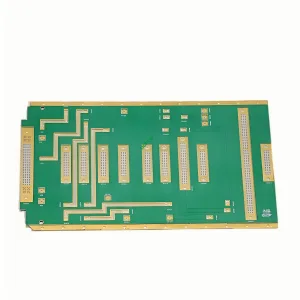
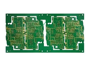
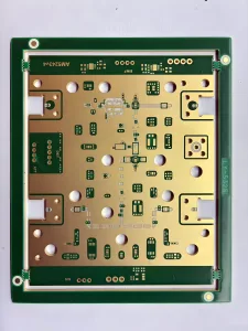
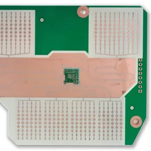
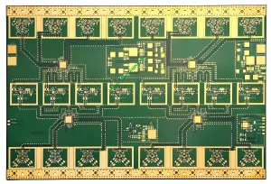
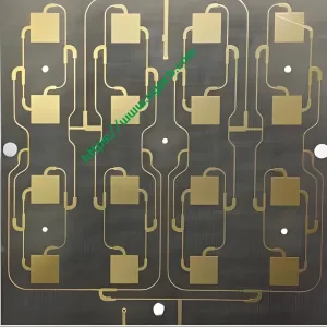
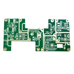
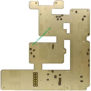
UGPCB bietet a12-Layer-Hochfrequenz-Hybrid-Leiterplatte Gebaut mit Rogers RO4350B und FR4. Die Dicke der fertigen Platine beträgt 1,6 mm mit 1 Unze Fertigkupfer. Die charakteristische Impedanz wird präzise auf 50 Ω gesteuert. Dieses Board eignet sich für HF-/Mikrowellen- und Mixed-Signal-Anwendungen, die sowohl Hochfrequenzleistung als auch Kosteneffizienz erfordern.
Warum ein Hybriddesign wählen?? In 5G-Basisstationen, Automobilradar, und Hochgeschwindigkeitskommunikationsmodule, HF-Schaltkreise benötigen für die Signalintegrität verlustarme Rogers-Materialien. Digitale Steuerkreise, Energieverwaltung, und Schnittstellen funktionieren perfekt mit Standard-FR4 bei viel geringeren Kosten. Ein komplettes Rogers-Board kostet 3 Zu 8 mal mehr als FR4. Eine vollständige FR4-Karte kann die HF-Leistungsanforderungen nicht erfüllen. Der Hochfrequenz-Hybrid-Leiterplatte schafft die optimale Balance zwischen Leistung und Kosten.
2. Produktklassifizierung und Einhaltung von Standards
2.1 Klassifizierung nach Materialkombination
Bei diesem Produkt handelt es sich um einHybrid-Laminat-Leiterplatte – Kombination von Rogers RO4350B (Hochfrequenzschichten) mit FR4 (Digital-/Leistungsschichten) durch Präzisionspressen. Unter IPC-4101, Rogers RO4350B ist ein glasfaserverstärktes Laminat mit Kohlenwasserstoff-/Keramikfüllung. FR4 ist ein flammhemmendes, kupferkaschiertes Laminat aus Epoxidharzgewebe.
2.2 Klassifizierung nach IPC-6012-Leistungsklasse
Für IPC-6012, dieser Vorstand tagtKlasse 2 (dedizierter Service für elektronische Produkte) UndKlasse 3 (Hochzuverlässige elektronische Geräte) Anforderungen.
2.3 Klassifizierung nach Frequenzbereich
Dies ist einHF-/Mikrowellenfrequenz-Leiterplatte. Die Rogers RO4350B-Schicht behält eine stabile Dielektrizitätskonstante von 3,48 ± 0,05 bei 10 GHz bei, Geeignet für Designs mit Frequenzen von 500 MHz bis Millimeterwellen.
3. Kernmaterialien und wichtige Leistungsparameter
3.1 Rogers RO4350B – Der „Goldstandard“ für Hochfrequenzschichten
Rogers RO4350B ist ein patentiertes Kohlenwasserstoffharzsystem mit keramischem Füllstoff, verstärkt mit Glasgewebe. Zu den wichtigsten Vorteilen gehören::
- Dielektrizitätskonstante (Dk): 3.48 ± 0.05 @ 10ghz (Prozesswert), 3.66 (Designwert). FR4 hat typischerweise ±5 % bis 10% Dk-Variante. RO4350B bietet nur ±1,4 % Toleranz, Bietet eine solide Grundlage für eine präzise Impedanzkontrolle.
- Dissipationsfaktor (Df): 0.0037 @ 10 GHz – deutlich niedriger als FR4, Gewährleistung einer verlustarmen Hochfrequenzsignalübertragung.
- Wärmeleitfähigkeit: 0.69 W/m·K bei 50°C (ASTM D5470).
- Volumenwiderstand: 1.2×10¹⁰ MΩ·cm (IPC-TM-650 2.5.17.1).
- Flammhemmende Bewertung: UL 94 V-0.
3.2 FR4 – Die kostengünstige Wahl für Digital- und Power-Layer
FR4 ist ein standardmäßiges flammhemmendes Epoxid-Glasgewebelaminat. Es bietet niedrige Kosten, ausgereifte Verarbeitung, und hohe mechanische Festigkeit. Es funktioniert gut für digitale Schaltkreise, Stromverteilung, und Bodenschichten.
3.3 12-Layer-Hybrid-Stackup-Struktur
Dieses Produkt verwendet a12-Layer-Hybrid-Aufbau. Die äußeren Schichten und kritischen HF-Signalschichten verwenden Rogers RO4350B-Kerne. Die inneren Schichten nutzen FR4-Kerne für die Stromversorgung, Boden, und langsame digitale Signale. Die Gesamtdicke der Platte beträgt 1,6 mm. Die Dicke des fertigen Kupfers beträgt 1OZ (35μm).
3.4 Zusammenfassung der wichtigsten Leistungsparameter
| Parameter | Spezifikation | Test-/Referenzstandard |
|---|---|---|
| Laminieren | Rogers RO4350B + FR4 | - |
| Schichtzahl | 12 Schichten | - |
| Dicke der fertigen Platte | 1.6mm | IPC-6012 |
| Fertige Kupferdicke | 1OZ (35μm) | IPC-6012 |
| Charakteristische Impedanz | 50Oh | IPC-2141 / IPC-2251 |
| Dielektrikumsdicke | 0.508mm | - |
| Dielektrizitätskonstante (Dk) | 3.48 ± 0.05 @ 10ghz | Rogers RO4350B Datenblatt |
| Wärmeleitfähigkeit | 0.69 W/m·K bei 50°C | ASTM D5470 |
| Flammhemmende Bewertung | UL 94 V-0 | UL 94 |
| Volumenwiderstand | 1.2×10¹⁰ MΩ·cm | IPC-TM-650 2.5.17.1 |
4. Konstruktionsüberlegungen: Vier Grundprinzipien für Hochfrequenz-Hybrid-Leiterplatten
4.1 Impedanzkontrolle – Erreichen des 50-Ω-Ziels
Impedanzkontrolle ist zentral für Hochfrequenz -PCB Design. Der 50-Ω-Standard ist die am häufigsten verwendete Impedanz in HF-Systemen. Dieses Produkt hält die Impedanz bei 50Oh um maximale Leistungsübertragung und minimale Signalreflexion zu gewährleisten.
Die Präzision der Impedanz hängt von der Dicke des Dielektrikums ab, Dielektrizitätskonstante, und Spurbreite. Die Dk-Toleranz von RO4350B von ±1,4 % bietet einen klaren Vorteil gegenüber ±5 % von FR4 10% Variation. Eine kritische Anmerkung: weil RO4350B einen niedrigeren Dk hat, Die Breite der Signalspuren auf Rogers-Schichten muss ungefähr sein 10% Zu 15% breiter als auf FR4-Schichten für 50-Ω-Designs. Zusätzlich, Eine Variation der dielektrischen Dicke von ±0,5 mil kann die Impedanz auf einer 10 mil Rogers-Mikrostreifenleitung um etwa ±2 Ω verschieben – eine präzise Kontrolle der Dicke ist daher unerlässlich.
4.2 Stackup-Design – Leistung und Kosten in Einklang bringen
Das Stackup-Design beeinflusst die Signalintegrität, Machtintegrität, EMC -Leistung, und Komplexität der Impedanzsteuerung. Dieser 12-Lagen-Aufbau folgt diesen Prinzipien:
- HF-Signalschichten werden mithilfe von Mikrostreifenstrukturen auf den äußeren Rogers RO4350B-Schichten platziert, um Übertragungsverluste zu minimieren.
- Erdungs- und Stromschichten werden auf FR4-Schichten platziert, Bereitstellung stabiler Referenzebenen.
- Ebenensymmetrie Hält das mechanische Gleichgewicht aufrecht, um Verformungen zu verhindern.
- Materialverträglichkeit – RO4350B kann mit den gleichen Methoden wie FR4 verarbeitet werden, Dadurch entfallen die speziellen Durchgangsbehandlungen, die für PTFE-basierte Materialien erforderlich sind.
4.3 Wärmemanagement – 0.69 W/m·K Wärmeableitung
Dieses Produkt erreicht 0.69 W/m · k Wärmeleitfähigkeit. In Leiterplatte Thermalmanagement, Wärmeleitfähigkeit k (W/m · k) misst, wie effizient ein Material Wärme überträgt. RO4350B 0.69 W/m·K übertrifft Standard FR4 deutlich (etwa 0.25 Zu 0.3 W/m · k), Ermöglicht eine effektivere Wärmeableitung von Hochleistungs-HF-Geräten.
4.4 Dimensionsstabilität – Niedriger WAK sorgt für Zuverlässigkeit
Der Z-Achsen-Wärmeausdehnungskoeffizient des RO4350B (CTE) Ist 32 ppm/° C. (-55°C bis 288 °C). Dies entspricht weitgehend dem CTE von Kupfer (etwa 17 ppm/° C.), Gewährleistung einer durchkontaktierten Bohrung (PTH) Zuverlässigkeit bei Temperaturwechsel. Die CTE-Werte der X- und Y-Achse betragen 10 ppm/°C und 12 ppm/°C bzw. Die Glasübergangstemperatur (Tg) über 280°C, Beibehaltung stabiler Expansionseigenschaften bei allen Verarbeitungstemperaturen.
5. Arbeitsprinzip: Wie übertragen sich Hochfrequenzsignale in einer Hybrid-Leiterplatte??
In Hochfrequenzschaltungen, Signale breiten sich als elektromagnetische Wellen aus und nicht als einfache Logikpegel „0“ und „1“.. DerHochfrequenz-Hybrid-Leiterplatte funktioniert über mehrere Mechanismen:
Signalübertragung: Hochfrequenzsignale werden in Mikrostreifen- oder Streifenleitungsstrukturen auf der RO4350B-Schicht übertragen. Der niedrige Dk des RO4350B (3.48) und niedrige Df (0.0037) Stellen Sie sicher, dass sich Signale mit minimalem Einfügungsverlust ausbreiten.
Impedanzübereinstimmung: Präzise Kontrolle der Spurbreite, dielektrische Dicke, und die Dielektrizitätskonstante legt die charakteristische Impedanz auf 50 Ω fest. Dies entspricht der Quelle, Übertragungsleitung, und Last – Maximierung der Leistungsübertragung und Minimierung der Signalreflexion.
Zwischenschichtverbindung: Hochfrequenzsignalschichten (Rogers) Verbindung zu Digital-/Stromversorgungsebenen herstellen (FR4) durch plattierte Durchgangslöcher (PTH). Der niedrige Z-Achsen-WAK des RO4350B (32 ppm/° C.) gewährleistet die PTH-Zuverlässigkeit während des Temperaturwechsels.
Thermalmanagement: Die Wärme von Hochleistungs-HF-Geräten wird durch die RO4350B-Schicht geleitet (0.69 W/m · k) zu den FR4-Schichten und externen Wärmeableitungsstrukturen, Halten Sie Geräte innerhalb sicherer Betriebstemperaturen.
6. Herstellungsprozess: Vom Material bis zum fertigen 12-Lagen-Hybridboard
6.1 Wareneingangskontrolle
Überprüfen Sie die Rogers RO4350B- und FR4-Kerne. Überprüfen Sie die Dielektrizitätskonstante, Dicke, Kupferfolienqualität, und andere Parameter gemäß den Anforderungen von IPC-4101 und Rogers-Datenblättern.
6.2 Herstellung von Innenschichtschaltungen
Übertragung von Prozessschaltkreismustern, Radierung, und AOI-Inspektion an FR4-Innenschichten (für Strom und Erde).
6.3 Braunoxidbehandlung
Tragen Sie eine braune Oxidbehandlung auf die Kupferoberflächen der Innenschicht auf, um die Schichthaftung zu verbessern.
6.4 Layup und Laminierung
Dies ist der wichtigste SchrittHy-Hybrid-Leiterplatte Herstellung:
- Stapeln Sie Rogers-Kerne, FR4-Kerne, und Prepreg entsprechend dem entworfenen 12-Lagen-Aufbau.
- Verwenden Sie eine Stufenlaminierung, um Spannungen und Dimensionsverzerrungen zu vermeiden, die durch CTE-Unterschiede zwischen Rogers und FR4 verursacht werden.
- Optimieren Sie die Prepreg-Auswahl (z.B., Low-Flow-Prepreg) und Laminierungsparameter, um Spannungen zwischen den Schichten zu minimieren.
6.5 Bohren und Desmear
Führen Sie mechanisches Bohren und Laserbohren durch (für blinde/vergrabene Vias, falls erforderlich). Anschließend Desmear durchführen und für die Lochmetallisierung vorbereiten.
6.6 Lochmetallisierung und -plattierung
Wenden Sie eine stromlose Kupferabscheidung und eine elektrolytische Verkupferung an, um 1 Unze zu erreichen (35μm) fertige Kupferdicke.
6.7 Herstellung von Außenschichtschaltungen
Erstellen Sie HF-Signalspuren auf den äußeren Schichten von Rogers. Kontrollieren Sie die Leiterbahnbreiten streng, um eine Impedanzgenauigkeit von 50 Ω sicherzustellen.
6.8 Lötmaske und Oberflächenbeschaffenheit
Tragen Sie Lötstopplack und Oberflächenfinish auf (z.B., ZUSTIMMEN) um die Lötbarkeit und Oxidationsbeständigkeit sicherzustellen.
6.9 Elektrische Prüfung und Endkontrolle
Führen Sie durch 100% elektrische Prüfung (einschließlich Impedanzprüfung und Durchgangsprüfung). Führen Sie eine Sichtprüfung durch, Dimensionsmessung, und Zuverlässigkeitsstichproben.
7. Leistungsvorteile: Warum sollten Sie sich für die 12-lagige Hochfrequenz-Hybridplatine von UGPCB entscheiden??
7.1 Überlegene Hochfrequenzleistung
RO4350B liefert Dk = 3,48 ± 0,05 bei 10 GHz und Df = 0.0037 @ 10ghz. Diese Eigenschaften sorgen für geringe Verluste, Signalübertragung mit geringer Dispersion von 500 MHz bis hin zu Millimeterwellenfrequenzen.
7.2 Präzise 50-Ω-Impedanzregelung
Die Dk-Toleranz von ±1,4 %, kombiniert mit einer präzisen Steuerung der dielektrischen Dicke, ermöglicht eine hochpräzise charakteristische Impedanz von 50 Ω und erfüllt damit die Impedanzanpassungsanforderungen von HF-Systemen.
7.3 Ausgezeichnetes Preis-Leistungs-Verhältnis
Im Vergleich zu einer vollständigen Rogers-Lösung, DieRogers-FR4-Hybridlösung spart ca 60% Zu 70% Dies senkt die Materialkosten und bietet gleichzeitig eine deutlich bessere HF-Leistung als ein vollständiges FR4-Design.
7.4 Zuverlässige mechanische und thermische Leistung
- UL 94 V-0 Flammschutzklasse
- Z-Achse CTE von nur 32 ppm/° C.
- Tg > 280°C
- Wärmeleitfähigkeit von 0.69 W/m · k
7.5 Kompatibel mit FR4-Verarbeitung
RO4350B kann mit den gleichen Methoden wie Standard-FR4 verarbeitet werden. Es sind keine speziellen Durchgangsbehandlungen oder Handhabungsverfahren erforderlich – wodurch die Herstellungskosten gesenkt und die Durchlaufzeiten verkürzt werden.
8. Typische Anwendungen
8.1 5G-Kommunikationsbasisstationen
Antennenarrays und HF-Frontends (Leistungsverstärker, rauscharme Verstärker) erfordern RO4350B-Schichten für verlustarme HF-Verbindungen. Basisbandprozessoren und digitale Schnittstellen können auf FR4-Schichten platziert werden.
8.2 Automobil-Millimeterwellenradar (77GHz)
Speisenetzwerke zwischen Sende-/Empfangsantennen und Transceiver-Chips nutzen Rogers-Materialien für eine präzise Phasenkonsistenz. Radarcontroller und CAN-Bus-Schnittstellen verwenden FR4-Schichten.
8.3 Satellitenkommunikation und Mikrowellen-Punkt-zu-Punkt-Übertragung
Zu den Anwendungen gehören Mobilfunk-Basisstationsantennen und Leistungsverstärker, Mikrowelle Punkt-zu-Punkt (P2P) Links, und rauscharmer Satelliten-Direct-to-Home-Block (LNB) Abwärtskonverter.
8.4 Optische Hochgeschwindigkeitsmodule und kabelgebundene Kommunikation
In 400G-Treiberplatinen für optische Module, Hochgeschwindigkeits-SerDes-Differentialpaare (≥56 Gbit/s PAM4) erfordern verlustarme Substrate, um die Qualität des Augendiagramms aufrechtzuerhalten. FPGA-Logik und DDR-Speicher können FR4 verwenden.
8.5 RFID und drahtlose Sensorik
Zu den Anwendungen gehören RFID-Tags, drahtlose Datenerfassungssysteme, drahtlose Fernbedienungen, und Telemetriesysteme.
9. Warum wählen Sie UGPCB??
UGPCB verfügt über umfangreiche Erfahrung in den Bereichen Hochfrequenz-Materialeigenschaften und Hybridverarbeitung – einschließlich der Prozesssteuerung, Kupferbeschichtung, Laminierungsschemata, RF-Trace-Toleranzen, und Impedanzparametersteuerung. Wir verpflichten uns dazu:
- ✅ 100% elektrische Prüfung (einschließlich Impedanzprüfung)
- ✅ Strikte Einhaltung der Standards IPC-6012 und IPC-4101
- ✅ Vollständige Rückverfolgbarkeit der Prozessqualität
- ✅ Professionelles Ingenieurteam, das DFM bereitstellt (Design für die Herstellung) Unterstützung

10. Jetzt anfragen – Holen Sie sich Ihre individuelle Lösung
UGPCB12-Schicht Rogers RO4350B+FR4 Hochfrequenz-Hybrid-Leiterplatte ist Ihre optimale Lösung für die 5G-Kommunikation, Automobilradar, Satellitenkommunikation, und optische Hochgeschwindigkeitsmodule – ein ausgewogenes Verhältnis zwischen Leistung und Kosten.
📧Senden Sie jetzt Ihre Anfrage. Unser RF-PCB-Engineering-Team wird Ihnen innerhalb von 24 Stunden antworten 24 Stunden mit:
- Maßgeschneiderte Stackup-Designvorschläge
- Präzise 50-Ω-Impedanzkontrollberechnungen
- Wettbewerbsfähige Mengenpreise
- Empfehlungen zur DFM-Herstellbarkeitsoptimierung
Machen Sie UGPCB zu Ihrem vertrauenswürdigen Partner für Hochfrequenz-Hybrid-PCB-Projekte!