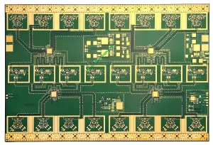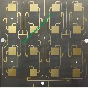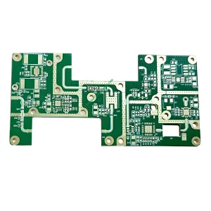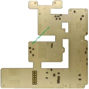
1. Présentation du produit: A 6-Layer Hybrid PCB Balancing 5G RF Performance and Cost
Modern electronic devices often combine RF front-ends, high-speed digital signals, and power management on one board. Using expensive high-frequency materials for the entire board is neither economical nor necessary. This logic gave birth to thePCB hybride haute fréquence.
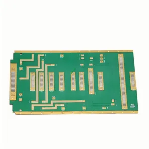
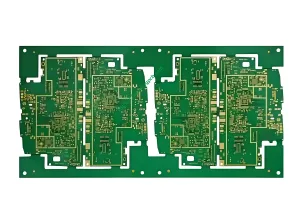
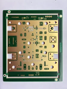
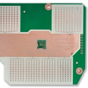
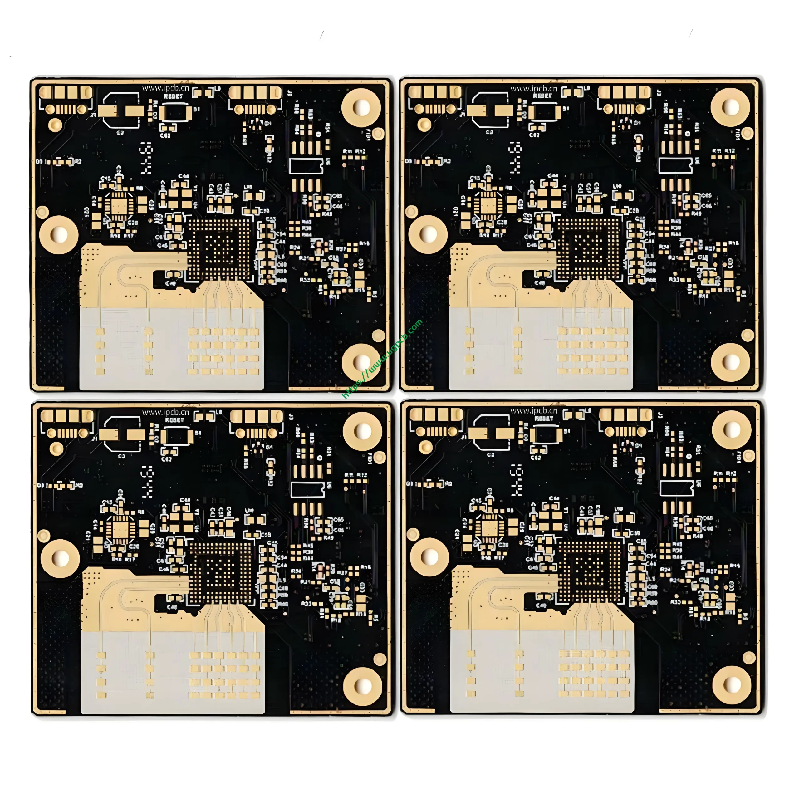
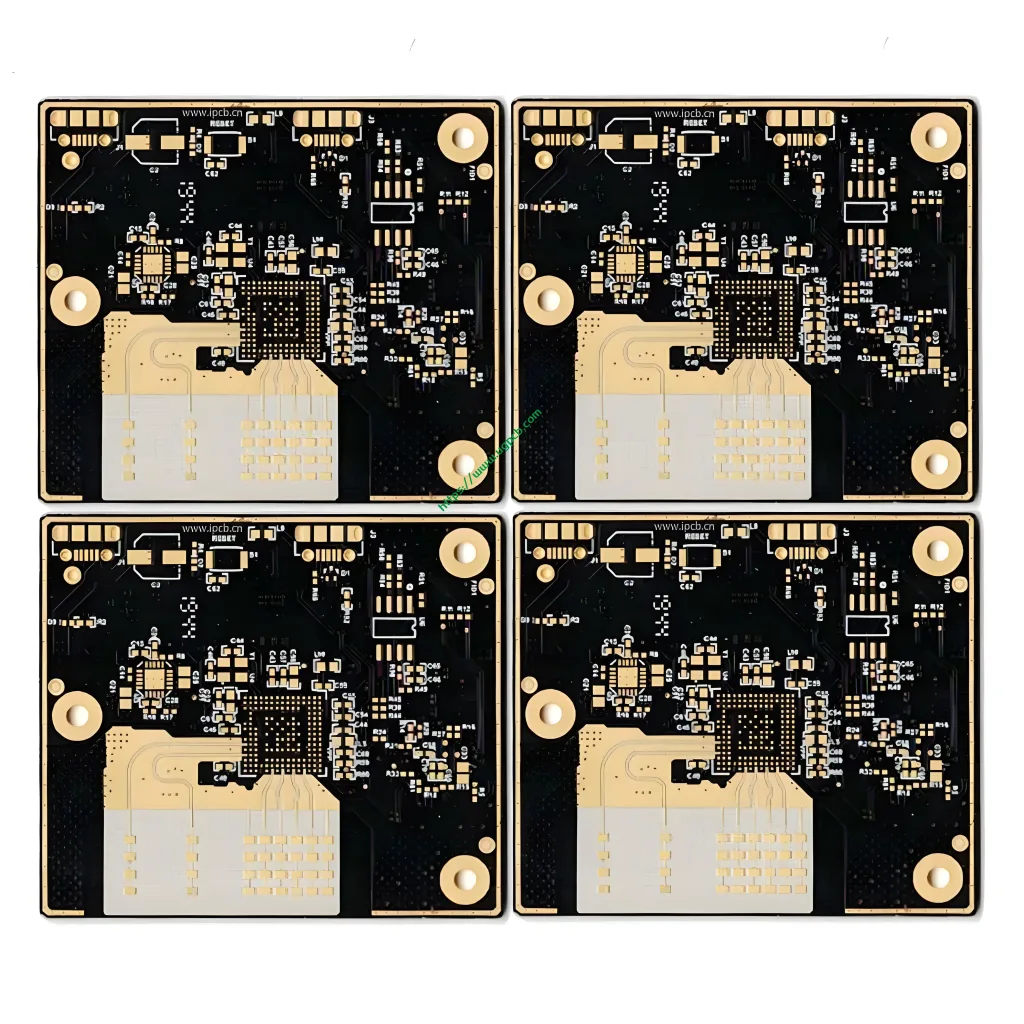
UGPCB RO4835 + IT180 6-Layer High Frequency Hybrid PCB realizes this concept. It laminates Rogers RO4835 high-frequency laminate avec ITEQ IT180 high-Tg FR-4 material in a single stackup. The final board has 1.5mm total thickness, 1OZ finished copper, et 50 ohm characteristic impedance.
RF signal layers use RO4835 to ensure signal integrity. Power and control layers use IT180 to cut material cost and provide mechanical support. This hybrid approach reduces material cost by30%–50% compared to a full Rogers solution. RF performance remains nearly unchanged. This makes it the top choice for cost-sensitive mass production projects like 5G base stations, 77 Radar automobile GHz, and aerospace communications.
2. Définition: What is “RO4835 + IT180 High Frequency Hybrid PCB”?
UNPCB hybride haute fréquence bonds two or more different dielectric materials into one multilayer board. The core idea is simple – use expensive high-frequency material only on RF signal layers. Use lower cost standard FR-4 on other layers for mechanical strength and lower cost.
RO4835 is a hydrocarbon/ceramic-filled thermoset high-frequency laminate from Rogers’ RO4000® series. It offers very low dielectric loss (Df = 0.0037 @ 10 GHz) et constante diélectrique stable (Ne sait pas = 3.48 ± 0.05). Unlike PTFE-based materials, RO4835 works with standard FR-4 processing. No special plasma etching or surface treatment is needed.
IT180 is a high-Tg lead-free epoxy FR-4 laminate from ITEQ. Its glass transition temperature (Tg) is 175°C (Méthode DSC). Ne pas savoir ≈ 4.1 et Df ≈ 0.016 à 10 GHz. IT180 offers excellent CAF resistance, low Z-axis CTE, and good through-hole reliability. It is widely used in automotive electronics, fonds de panier de communication, and server motherboards.
Combining RO4835 and IT180 creates an electrically isolated and thermally compatible interface. RO4835 guarantees signal integrity. IT180 provides rigidity and cost advantages.
3. Classement scientifique (Per IPC and UL Standards)
According to IPC-4101 “Specification for Base Materials for Rigid and Multilayer Printed Boards”, this product belongs to theHybrid Multilayer PCB catégorie.
- Per IPC-4103: RO4835 belongs to high frequency circuit laminates.
- Per IPC-4101C/126: IT180 belongs to high-Tg FR-4 laminates.
- Type de carte: Rigid Multilayer PCB.
- Nombre de couches: 6 couches (IDH options available).
- Application: RF/Microwave PCB for RF front-ends, radar à ondes de millimètres, and mixed-signal processing.
- Finition de surface: ACCEPTER (or par immersion au nickel autocatalytique) pour le brasage sans plomb et le collage de fils fins.
4. Key Design Considerations for Hybrid Stackup
Designing a hybrid PCB haute fréquence requires more than simply stacking RO4835 and IT180. Four design rules determine success.
4.1 Impedance Control and Dielectric Constant Matching
This product targets50 ohm characteristic impedance – the standard for RF and microwave systems. To achieve accurate 50Ω control, you must account for the Dk of both RO4835 and IT180 layers.
- RO4835 (Couches de signaux RF): Ne sait pas = 3.48 ± 0.05 @ 10 GHz (valeur de processus); Ne sait pas = 3.66 (valeur de conception). Utiliser 3.66 for microstrip or coplanar waveguide geometry calculations to get the best impedance match.
- IT180 (inner/power layers): Ne sait pas = 4.4 @ 1 MHz; Ne sait pas = 4.1 @ 10 GHz. Avoid routing RF signals vertically across layers with different Dk values. Impedance steps cause signal reflections.
4.2 Managing CTE Mismatch
RO4835 in-plane CTE (X/Y axes) is 10–12 ppm/°C. Typical FR-4 CTE is about 17 ppm/°C. The difference in thermal expansion can cause warpage, délaminage, or even board bursting during lamination and reflow.
Common countermeasures include: keeping stackup symmetrical (same thickness and material type on top and bottom), using stepped lamination (gradual temperature and pressure rise), and adding anchoring copper in transition areas for mechanical constraint.
4.3 Layer Stackup and Signal Layer Assignment
For a 6-layer RO4835 + IT180 hybrid board, the recommended symmetrical stackup is:
| Couche | Matériel | Fonction |
|---|---|---|
| Couche 1 (Haut) | RO4835 | Microruban RF / antenna signal |
| Couche 2 | Couche intérieure | Plan de masse de référence |
| Couche 3 | Noyau IT180 FR-4 | Numérique à faible vitesse / pouvoir |
| Couche 4 | Noyau IT180 FR-4 | Plan de masse |
| Couche 5 | Couche intérieure | Plan de masse de référence |
| Couche 6 (Bas) | RO4835 | Microruban RF / réseau d'alimentation |
This symmetrical design minimizes asymmetric warpage from thermal stress. Both top and bottom layers use RO4835 – a sandwich structure. The inner IT180 core provides rigidity and cost savings.
4.4 Isolating RF from Digital Signals
The Dk difference between RO4835 (~3.48) and IT180 (~4.1) il s'agit de 0.6. If a high-frequency signal crosses the hybrid interface, reflections and mode conversion will increase insertion loss significantly. Donc, route all high-speed/RF traces only on RO4835 layers. Never route RF across the hybrid boundary into the IT180 region.
5. Principe de fonctionnement: Why RO4835 Excels at High Frequencies?
The core challenge of high-frequency circuits is simple: higher signal frequency means greater parasitic loss in the PCB substrat. Two key parameters determine this loss – dielectric constant (Ne sait pas) et facteur de dissipation (Df).
5.1 Constante diélectrique (Ne sait pas)
Dk measures how much electrical energy the material can store. The smaller the Dk change across frequency, the better the impedance consistency over a wide bandwidth. RO4835’s Dk is3.48 ± 0.05 à 10 GHz (valeur de processus). Its thermal stability is only 50 ppm/°C de -50°C à 150°C. That means Dk barely drifts with temperature.
5.2 Facteur de dissipation (Df)
Df (tangente de perte) directly measures signal energy lost as heat in the dielectric. Lower Df means less lost energy. RO4835’s Df is only0.0037 à 10 GHz. For comparison, standard FR-4 has Df around 0.02 à 1 GHz. RO4835’s loss is about1/5 that of FR-4.
RO4835 achieves this low loss through its unique hydrocarbon/ceramic filler system. Hydrocarbon provides a low-polarity molecular backbone. Ceramic filler stabilizes mechanical dimensions and improves thermal conductivity. Après durcissement à haute température, the material forms a cross-linked thermoset network – which is exactly why RO4835 works with standard FR-4 PCB processes.
6. Applications: Five Core Use Cases for RO4835 + IT180 Hybrid PCBs
The value of this hybrid PCB is not just in its electrical performance – but in its reliable operation under real-world conditions. Below are five major application areas.
6.1 5G infrastructure de communication
5G millimeter-wave bands (par ex., n257/n258/n261, 24.25–29.5 GHz) demand very low PCB loss. According to a report by 360iResearch, the global 5G PCB market reached $22.3 milliards dans 2025 et devrait croître jusqu'à $59.44 milliards 2032 à un TCAC de 15.03%.
RO4835 + IT180 hybrid PCBs are used in 5G small cells, massive MIMO antenna arrays, et modules frontaux RF. They control material cost in mass production while meeting strict insertion loss requirements.
6.2 77 Radar automobile GHz (Adas)
Modern ADAS systems use 77 Radar à ondes millimétriques GHz. This is one of the most representative applications for high frequency hybrid PCBs. RO4835’s Dk at 77 GHz is about 3.2 (down from 3.48 à 10 GHz). Combined with LoPRO® reverse treated copper foil, insertion loss is minimized.
IT180’s Tg of 175°C and T260 > 60 minutes provide high thermal reliability. This allows the radar module to survive harsh thermal cycling from -40°C to +125°C near the engine compartment.

6.3 Aerospace and Satellite Communications
Aerospace applications require MATÉRIAUX PCB to remain reliable under vacuum, high radiation, and extreme temperatures. RO4835 offers 10 times better oxidation resistance than conventional thermoset materials. It also passes non-voiding delamination tests, making it a trusted choice for LEO satellite communication payloads and phased array antennas.
6.4 RF Power Amplifiers
In base station power amplifier (Pennsylvanie) modules, RO4835’s low loss directly translates to higher output power and lower heat generation. Its thermal conductivity of 0.69 W / m · k (measured) quickly conducts heat away from PA chips to heat sinks, extending device lifetime.
6.5 High-Speed Mixed-Signal Boards
When a board contains high-speed ADCs/DACs, FPGA, and RF front-end channels, crosstalk becomes a serious issue. Le RO4835 + IT180 hybrid creates a natural dielectric constant barrier between RF and digital layers. This effectively suppresses digital noise coupling into RF paths.
7. Matériels: Detailed Technical Specifications of RO4835 and IT180
The table below lists official key parameters for RO4835 and IT180 with test method references.
| Paramètre | RO4835 (Rogers) | IT180 (ITEQ) | Norme d'essai / Source |
|---|---|---|---|
| Nsp @ 10 GHz | 3.48 ± 0.05 (processus) | 4.1 | IPC-TM-650 2.5.5.5 / 2.5.5.13 |
| Nsp @ 1 MHz | - | 4.4 | IPC-TM-650 2.5.5.9 |
| Df @ 10 GHz | 0.0037 | 0.016 | IPC-TM-650 2.5.5.5 / 2.5.5.13 |
| Tg (DSC) | ≥280° C | 175° C | IPC-TM-650 2.4.24.3 |
| Td (5% perte de poids) | 390° C | 345° C | ASTM D3850 / TGA |
| Conductivité thermique | 0.66–0.69 W/m·K | - | ASTM C518 / ASTM D5470 |
| Indice d'inflammabilité | UL 94 V-0 | UL 94 V-0 | UL 94 |
| Résistivité volumique | 5 × 10⁸ MΩ·cm | Pour IPC-4101 | IPC-TM-650 2.5.17.1 |
| CTE (X/Y axis) | 10 / 12 ppm/°C | 11–13 / 13–15 ppm/°C | IPC-TM-650 2.1.24 / Tma |
| CTE (Z axis, a1) | 31 ppm/°C | 45 ppm/°C | IPC-TM-650 2.1.24 / Tma |
| Moisture absorption | 0.05% | - | ASTM D570 |
Data accuracy note: All values above have been verified against official Rogers Corporation and ITEQ data sheets. The volume resistivity value 5×10⁸ MΩ·cm is from Rogers official documentation. Some earlier documents use 1.2×10¹⁰ Ω·cm which may result from unit conversion but does not change the conclusion that the material has excellent insulating properties.
8. Fonctionnalités de performance
Based on the technical parameters above, this high frequency hybrid PCB offers five core advantages:
- Very low signal loss: Df = 0.0037 @ 10 GHz – about 1/5 of ordinary FR-4. In 5G mmWave bands, this means longer transmission distance, lower errors, and less heating.
- Constante diélectrique stable: Ne sait pas = 3.48 ± 0.05 @ 10 GHz. Very stable over wide frequency and temperature ranges. Ensures accurate 50Ω impedance under all operating conditions.
- Excellent heat and oxidation resistance: RO4835 has 10 résistance à l'oxydation fois supérieure à celle des matériaux thermodurcis traditionnels. It works long-term in high-temperature air without significant degradation.
- Superior manufacturability: No special surface treatment (like plasma etching) needed. Fully compatible with standard FR-4 processes. This shortens lead times significantly.
- Cost-effective design: Only RF critical layers use RO4835. Inner layers use IT180. Material cost is about 30%–50% lower than a full Rogers solution under the same electrical constraints.
9. Processus de fabrication: 8 Key Steps from Material to Finished Board
A qualified RO4835 + IT180 high frequency hybrid PCB goes through the following eight critical processes:
① Incoming material inspection – Sample test Dk/Df consistency of RO4835 and IT180 batches. Ensure parameters meet Rogers and ITEQ official specifications.
② Inner layer circuit formation – Pattern transfer and etching on IT180 layers for digital signal lines and power/ground planes.
③ Brown oxide treatment – Chemically roughen inner layer copper surfaces. Improve adhesion with prepreg during lamination.
④ Lamination – The most critical step. Stack RO4835, préampe, and IT180 cores in a symmetrical stackup. Load into a vacuum press. Precisely control temperature ramp rate, pressure curve, and dwell time to minimize stress from CTE mismatch. For this 6-layer product, single high-temperature lamination is typical. HDI designs use sequential lamination.
⑤ Drilling – Use solid carbide drills or laser drilling. Optimize parameters for 1.5mm board thickness to ensure hole wall roughness meets PTH copper plating requirements.
⑥ Electroless copper / panel plating – Metallize through-holes. Establish electrical interconnection between layers.
⑦ Outer layer circuit formation – Fabricate 50Ω impedance microstrip lines or RF traces on top and bottom RO4835 layers. Use controlled impedance etching to keep trace width tolerance within ±5%.
⑧ Surface finish - ACCEPTER (or par immersion au nickel autocatalytique) pour le brasage sans plomb et le collage de fils fins. Typical gold thickness 0.05–0.1 μm. Épaisseur du nickel 3 à 5 μm.
⑨ Electrical test and flying probe - 100% electrical test including open/short and TDR impedance test. Ensure each board meets 50Ω impedance tolerance.
10. Physical Structure of the 6-Layer Hybrid Board
Below is the physical construction of UGPCB’s RO4835 + IT180 6-layer board (de haut en bas):
| Article | Composant | Matériel | Épaisseur typique | Fonction |
|---|---|---|---|---|
| 1 | Top copper foil | Cuivre ED (LoPRO® en option) | 1 once (≈35 μm) | Outer layer signal / antenne |
| 2 | Top dielectric | RO4835 | 0.127 mm | Isolation du signal haute fréquence |
| 3 | Cuivre intérieur (L2/L5) | Cuivre | 1 once | Plan de masse de référence |
| 4 | Noyau moyen | IT180 FR-4 | Par conception d'empilement | Signal numérique / couche de puissance |
| 5 | Noyau moyen | IT180 FR-4 | Par conception d'empilement | Plan de masse |
| 6 | Cuivre intérieur (L3/L4) | Cuivre | 1 once | Inner routing / pouvoir |
| 7 | Bottom dielectric | RO4835 | 0.127 mm | Isolation du signal haute fréquence |
| 8 | Bottom copper foil | Cuivre ED (LoPRO® en option) | 1 once (≈35 μm) | Bottom signal / réseau d'alimentation |
| 9 | Finition superficielle | ACCEPTER | 0.05–0,1 μm (Au) | Solderability and oxidation resistance |
Total board thickness is 1.5 mm including all copper and dielectric layers.
11. Product Selection Quick Reference
| Paramètre | Spécification | Customizable Range |
|---|---|---|
| Laminate combination | RogersRO4835 + ITEQ IT180 | RO4350B + FR-4 or other ITEQ series |
| Nombre de couches | 6 couches | Expandable to 4/6/8/10 layers plus HDI |
| Épaisseur du panneau | 1.5 mm | 0.8–3.0 mm (based on layer count and stackup) |
| Épaisseur du cuivre | Fini 1 once | 0.5 once / 1 once / 2 once |
| Contrôle d'impédance | 50 ohm (single-ended) | Differential 90Ω/100Ω and others |
| Épaisseur diélectrique | 0.127 mm | Based on stackup requirements |
| Ne sait pas (RO4835 à 10 GHz) | 3.48 ± 0.05 | Dépend du matériau |
| Df (RO4835 à 10 GHz) | 0.0037 | Dépend du matériau |
| Indice d'inflammabilité | UL 94 V-0 | Required |
| Finition superficielle | ACCEPTER | OSP, boîte à immersion, argent par immersion |
12. Why Choose UGPCB for Your Hybrid PCB Needs?
UGPCB has deep engineering experience in high frequency hybrid PCBs. We help customers avoid common risks like material incompatibility, layer delamination, and reliability test failures. Our core strengths include:
- ✅ Solid high-frequency design support – From impedance calculation (using Rogers MWI and Polar SI9000) to CTE stress simulation of stackups.
- ✅ Precise process control – X-ray real-time alignment and AOI ensure layer-to-layer registration within ±3 mil.
- ✅ Batch consistency – Even in mass production, RO4835 Dk batch variation stays within ±0.05. 50Ω impedance yield exceeds 98%.
- ✅ Fast response and on-time delivery – Strategic inventory of Rogers and ITEQ raw materials. Lead time for hybrid quick-turn PCBs is as short as 7–10 working days.
Demandez un devis maintenant
Le RO4835 + IT180 high frequency hybrid PCB is the best solution for balancing performance and cost. Whether you are designing a 5G small cell or qualifying a 77 GHz radar module for mass production, UGPCB provides one-stop service from engineering validation to volume manufacturing.
📧Contact UGPCB Engineering Team: sales@ugpcb.com
📞Technical Hotline: +86-XXX-XXXXXXX
🌐Visitez notre site Web: www.ugpcb.com
【Get Your Custom Quote Now】
Please provide the following information:
- PCB layer count and target board thickness
- Number of RF layers and frequency range
- Estimated annual volume (prototype / petit lot / production de masse)
- Impedance control requirements (single-ended/differential, target value and tolerance)
- Any special process requirements (forage arrière, buried/blind vias, forage à profondeur contrôlée, etc.)
L’équipe d’ingénierie de l’UGPCB répondra dans les plus brefs délais 24 hours with technical support and a detailed quote.
*All technical data in this document come from Rogers Corporation official data sheet (DS RO4835) and ITEQ IT-180A technical specification. Test methods follow IPC-TM-650 series and applicable ASTM standards. Market data source: 360iResearch “5G Printed Circuit Board Market” rapport (January 2026). UGPCB is responsible for the accuracy and timeliness of the data. For any technical questions, please contact our engineering team for confirmation.*