
1. 시장 배경: 자동차 전자 장치에 고신뢰성 PCB가 필요한 이유
최신 전기 자동차와 ADAS 시스템은 매년 더 많은 전자 부품을 사용합니다..
중국 상업 산업 연구소의 데이터에 따르면: 중국의 자동차 전자 시장은 1,690억 달러에 이르렀습니다. 2024, 와 10.95% 전년 대비 성장. 이러한 요구로 인해 엔지니어는 기존의 견고한 제품을 교체하게 되었습니다. PCB + 더욱 컴팩트하고 안정적인 솔루션을 갖춘 와이어 하니스.
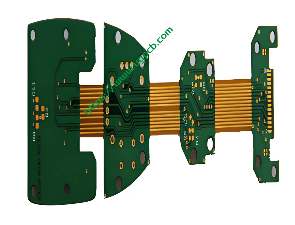
에이 리지드 플렉스 PCB 리지드 보드의 안정성과 플렉스 회로의 굽힘성을 결합한 제품입니다..
업계 연구에 따르면 Rigid-Flex로 전환하면:
-
~40% 설치 공간 절약
-
Reduce vibration‑related failures by ~65%
-
Lower BOM cost by ~22% through higher integration
The global automotive rigid‑flex PCB market is expected to exceed USD 5 10억 단위로 2025.
UGPCB designed the 자동차 PCB (HDI R-FPCB) – a high‑density interconnect rigid‑flex board that meets ISO 26262 and IPC‑6012DA Class 3 요구 사항. It is the ideal choice for your automotive rigid‑flex PCB prototype.
2. 제품 정의 & 과학적 분류
2.1 제품명 & 모델
-
제품명: 자동차 PCB (HDI R-FPCB) – Automotive‑Grade Rigid‑Flex HDI PCB
-
Model Code: HDI R-FPCB 1+2+1 구조
-
Focus Keyword: Automotive rigid‑flex PCB prototype (Yoast SEO focus keyword)
2.2 과학적 분류 (Based on IPC & UL Standards)
| Classification Method | 기준 | 범주 |
|---|---|---|
| By structure | IPC‑2223 | Rigid‑Flex Multilayer Board (≥3 conductive layers) |
| By HDI technology | IPC‑2226 | Type III – 2‑step HDI with “1+2+1” stackup, laser microvias |
| By performance class | IPC‑6013 | 수업 3 (high‑reliability, continuous operation) |
| By application | - | 자동차 전장 – ECU, ADAS, BMS, 인포테인먼트 |
2.3 주요 매개변수 (Quick Reference Table)
| 매개 변수 | 사양 |
|---|---|
| 모델 | 자동차 PCB (HDI R-FPCB) |
| 재료 | FR-4 + PI (폴리이미드) |
| Layer stackup | 1+2+1 (2‑step HDI rigid‑flex) |
| 솔더 마스크 색상 | 녹색 / 하얀색 |
| 완성 된 두께 | 1.2 mm |
| 구리 두께 | 0.035 mm (1 온스) |
| 표면 마감 | 2U만” (무전해 니켈 침지 금) |
| 최소. 선 너비 / 간격 | 0.1 mm / 0.1 mm |
| 애플리케이션 | Automotive electronics rigid‑flex PCB prototype |
테이블 1 – Core specifications of UGPCB Automotive PCB (HDI R-FPCB).
3. 스택업 & 구조: “1+2+1” 2‑Step HDI Rigid‑Flex
3.1 그만큼 1+2+1 Stackup Explained
이것 automotive rigid‑flex PCB prototype features a 1+2+1 HDI build‑up:
-
층 1 – Outer rigid layer (component mounting & 라우팅)
-
층 2 – 1st HDI build‑up (매장 / blind microvias)
-
층 3 – Core layer (contains PI flex area)
-
층 4 – 2nd HDI build‑up
-
층 5 – Outer rigid layer (bottom side routing & 납땜)
The flex area stays on the PI core and opens through the rigid coverlay. This design gives you both high routing density (HDI PCB) and 3D bendability (리지드 플렉스 PCB).
3.2 HDI Classification per IPC‑2226
IPC‑2226 defines HDI by: line width/spacing ≤ 100 μm, microvia pad < 400 μm, and density > 20 pads/cm².
우리의 0.1 mm line/space meets the standard. Laser microvias enable the 1+2+1 structure as II 형 (2‑스텝 HDI) – 자동차 전자 장치에 이상적.
| HDI 유형 (IPC‑2226) | 빌드업 기능 | 일반적인 응용 |
|---|---|---|
| I 형 I (1-단계) | 코어의 단일 마이크로비아 레이어 | 소비자 전자 장치 |
| II 형 (2-단계) | 측면당 빌드업 레이어 2개 | 자동차, 산업의, 고급 장치 |
| III 형 (≥3단계) | 모든 레이어 상호 연결 | 플래그십 스마트폰 |
3.3 재료: FR-4 + PI
-
단단한 부분 (FR-4) – 에폭시 유리 직조 직물. 무거운 부품에 대한 강력한 기계적 지지력 제공 (커넥터, 대형 IC).
-
플렉스 영역 (PI) – 폴리이미드 필름 (FCCL). Tg > 260℃, UL 94 V‑0 등급. 엔진 베이 온도를 견딤.
CTE (열팽창 계수) PI의 차이 (16–20ppm/°C) 그리고 FR-4 (14–18ppm/°C) 중요합니다. UGPCB는 –40°C ~ +125°C 열 순환에서 박리를 방지하기 위해 적층 매개변수를 제어합니다..
4. 고성능 Rigid-Flex HDI PCB 설계 지침
4.1 가는 선 & 공간 (0.1 mm / 0.1 mm)
달성 0.1 mm 추적/공간 1 OZ 구리는 허용합니다 50% 보다 높은 라우팅 밀도 0.15 mm 디자인.
자동차용 PCB 나중에 조립, 이 규칙을 따르세요:
-
임피던스 제어 – 차동 쌍 임피던스 일치 (90 오 / 100 오) FR-4 및 PI 영역 모두에 걸쳐.
-
길이 매칭 – 쌍 내 불일치 유지 < 0.5 PI의 Dk 때문에 플렉스 영역의 mm (3.4-3.5) FR-4와 다름 (4.2–4.5).
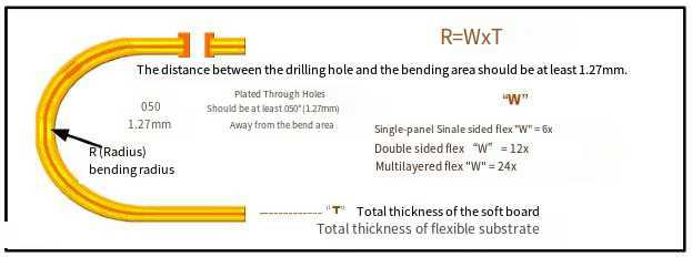
4.2 굽힘 반경 계산 (IPC‑2223)
Rigid‑flex PCB는 신뢰성을 위해 최소 굽힘 반경을 준수해야 합니다..
IPC‑2223 및 업계 관행에 따름:
Rmin, 정적=(6 에게 12)×티플렉스Rmin, 동적≥10×tflex
어디 티플렉스 = 전체 플렉스 영역 두께 (구리 + 커버레이).
일반적인 경우 0.2 mm 플렉스 스택, 정적 최소 반경은 1.2–2.4mm입니다.. UGPCB는 R ≥을 권장합니다. 6 도어 힌지 또는 시트 조절 장치의 동적 굽힘에 대한 mm.
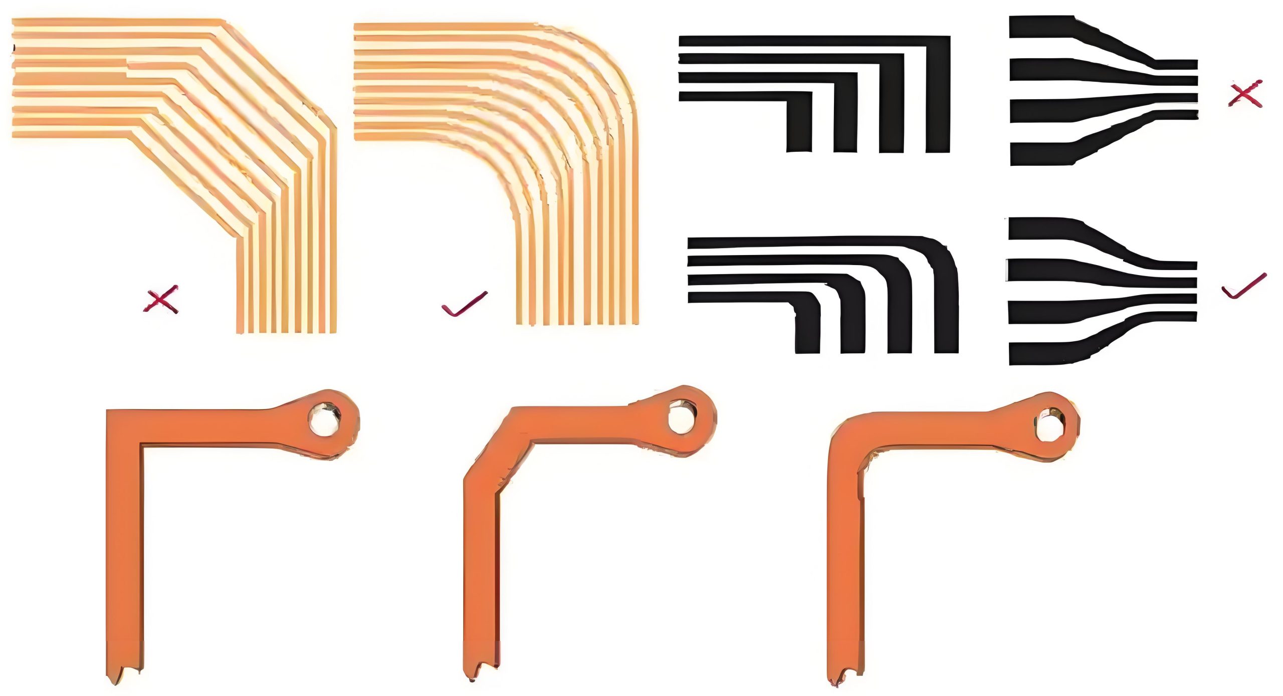
4.3 Rigid-Flex 전환 영역 - 핵심 사항
-
45° 테이퍼형 인터페이스 – Avoids stress concentration.
-
Route traces parallel to bend axis – Never cross the bend area perpendicularly.
-
Teardrop pads & rounded coverlay openings – Distribute mechanical stress.
-
사용 0.5 OZ copper on high‑flex zones - 1 OZ is stronger but less flexible.
5. 제조 공정 흐름 (ISO & IPC Compliant)
UGPCB follows IPC‑6013D for rigid‑flex qualification. 주요 단계:
-
Inner layer imaging – FR‑4 core and PI flex layer separately. AOI checks 0.1 mm lines.
-
레이저 드릴링 (눈이 먼 / buried microvias) - CO₂ laser removes FR‑4; UV laser for < 50 µm holes.
-
desmear & electroless copper – Activates hole walls for plating.
-
Via filling & panel plating – Blind vias filled with copper (무효율 < 5%).
-
Sequential lamination – Builds the 1+2+1 stack in two steps. Flex area is masked during rigid layer lamination.
-
외부 층 & 솔더 마스크 – Green or white LPI solder mask applied.
-
2U만” 표면 마감 – IPC‑4552 compliant: 3–7 µm Ni + ≥0.05 µm Au. Double gold thickness for corrosion resistance.
-
라우팅 & 전기 테스트 - 100% flying probe or fixture test.
6. 성능 & Reliability Data (IPC‑TM‑650)
| 시험 | 상태 | 요구 사항 | 기준 |
|---|---|---|---|
| Dielectric withstanding voltage | ≥1000 VDC | No breakdown | IPC‑TM‑650 2.5.7 |
| 단열성 저항 (normal) | ≥10^11 Ω | 통과하다 | IPC‑TM‑650 2.5.3 |
| 열 사이클링 | –40°C ↔125°C, 1000 사이클 | No delamination, ΔR < 10% | IPC‑TM‑650 2.6.7 |
| Damp heat | 85℃ / 85% RH, 1000시간 | IR ≥ 10^9 Ω | IPC‑6013 Class 3 |
| Vibration | 10–2000 Hz, 20g, 4h/axis | No intermittent opens | ISO 16750‑3 |
| 동적 굽힘 | r = 5 mm, 5000 사이클 | No open circuit | 산업 표준 |
All tests follow IPC‑TM‑650 methods and IPC‑6013 Class 3 요구 사항.
7. 주요 특징 & 응용 시나리오
7.1 Why Choose This Automotive Rigid‑Flex HDI PCB
-
1+2+1 HDI + rigid‑flex – High density plus bendability.
-
0.1 mm line/space – Supports BGA pitch ≤ 0.5 mm.
-
UL 94 V‑0 – Flame retardant (extinguishes within 10 초).
-
2U만” – 10~15년의 자동차 수명을 위한 두 배의 금 두께.
-
빠른 회전 프로토타입 – 7~10일 안에 샘플 준비.
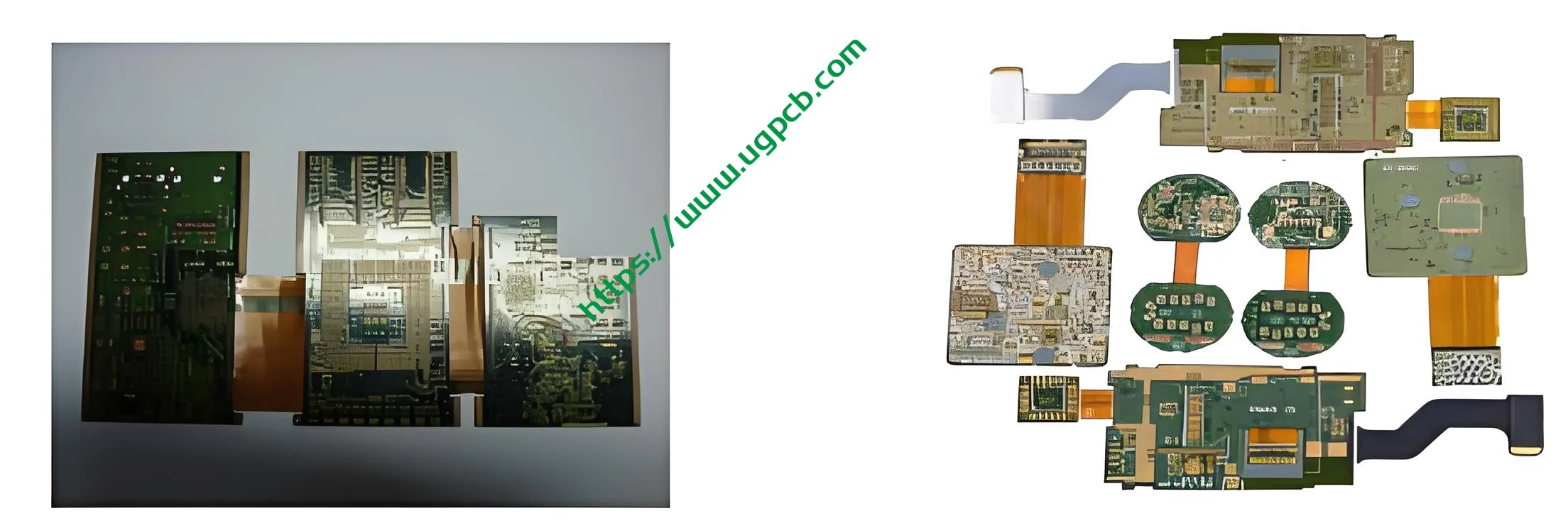
7.2 자동차 전자 PCB 프로토타입의 일반적인 사용 사례
-
ECU (엔진 제어 장치) – PI flex에 직접 통합된 센서 신호, 커넥터 제거.
-
ADAS 도메인 컨트롤러 – 레이더 / 카메라 모듈에는 고속 신호와 접이식 구조가 필요합니다..
-
인포테인먼트 시스템 – FPC 교체 + 하나의 리지드 플렉스 PCB가 포함된 BTB 커넥터.
-
BMS (배터리 관리 시스템) – UL이 포함된 스택형 전압/온도 채널 94 V-0 준수.
-
자동차 카메라 모듈 – 플렉스 섹션은 와이어 하니스 없이 도어 힌지를 통해 구부러집니다..
8. 자동차용 Rigid-Flex PCB 프로토타입을 위해 UGPCB와 협력해야 하는 이유?
-
IPC 회원 + UL 인증 – IPC‑6012DA를 완벽하게 준수 & IPC‑6013D.
-
16,000 m² 현대식 공장 – 연간 생산능력 600,000 m², 전용 HDI 생산 라인.
-
무료 DFM 검토 - 15+ 년 평균 경험. UGPCB는 스택업 및 굽힘 반경을 최적화하는 데 도움이 됩니다..
-
빠른 프로토타입 배송 – Rigid-Flex 샘플의 경우 7~10일.
-
무료 엔지니어링 상담 – CTE 불일치 분석, 임피던스 튜닝, 및 SMT 조립 조언.
9. 견적 받기 - 지금 바로 자동차용 Rigid‑Flex HDI PCB 프로토타입을 시작해 보세요.
Gerber 파일을 제출하거나 기술 요구사항을 공유하세요.. UGPCB는 이내에 응답합니다. 2 무료 스택업 추천 및 가격 견적이 포함된 시간.
지금 문의하세요 – 아래 간단한 양식을 작성해 주세요.:
-
회사명
-
핸드폰 / 위챗 / 왓츠앱
-
디자인 요구 사항 또는 목표 예산
UGPCB는 높은 신뢰성을 구축하는 데 도움이 됩니다., 고집적 자동차 전자 장치 – 한 번에 하나의 Rigid-Flex PCB.
선언
이 문서의 모든 사양과 데이터는 IPC‑2223을 기반으로 합니다., IPC‑2226, IPC‑6013, UL 94, 공개적으로 이용 가능한 시장 보고서 (중국 상업 산업 연구소, 2025). UGPCB는 기술 데이터를 업데이트할 권리를 보유합니다.. 최신 엔지니어링 지침은 UGPCB 영업팀에 문의하세요..


