

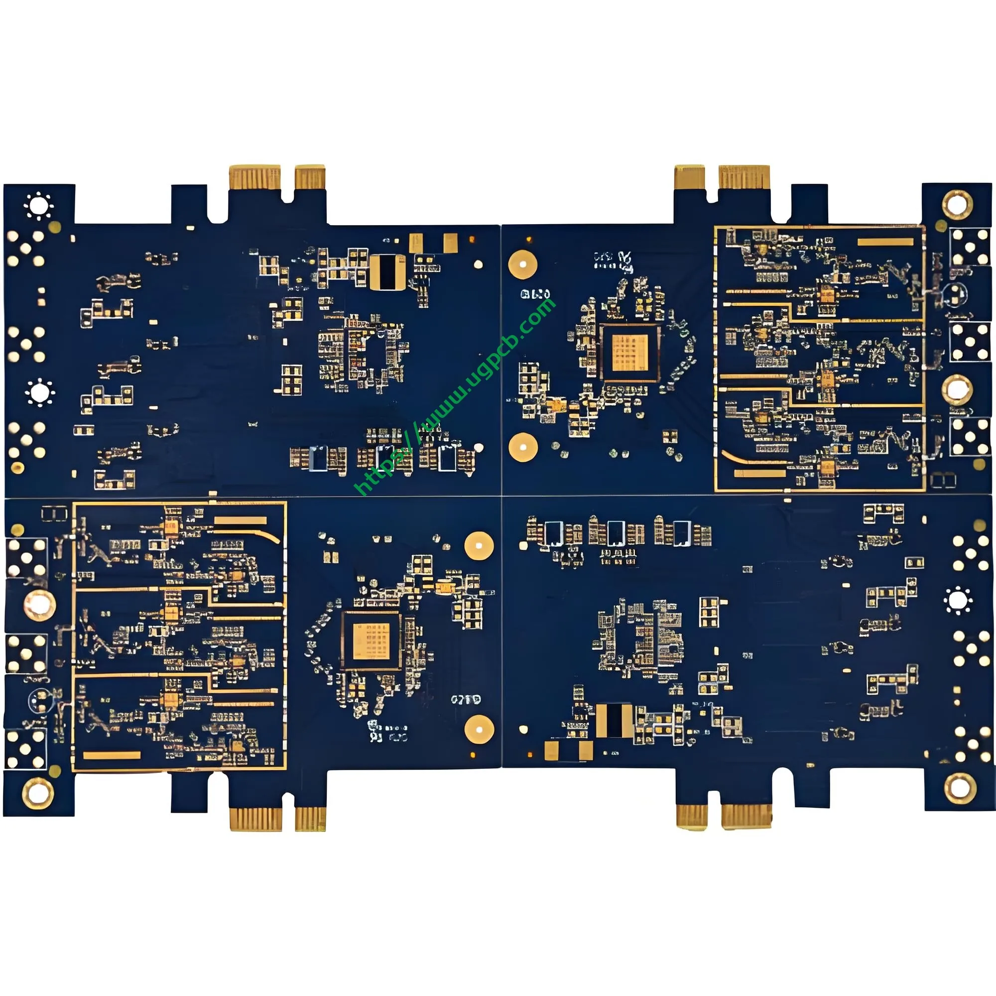
Prezentare generală a produsului: Ce este un PCB de hard disk mecanic al computerului?
Un hard disk mecanic de calculator PCB (Placă de circuit tipărită) este cea mai critică componentă de control electric din interiorul unui hard disk (HDD). Această placă poartă cipul de control principal, memorie cache, circuite de gestionare a puterii, și diverși conectori de interfață. Coordonează operațiile de citire/scriere a capului, controlul motorului axului, și comunicarea de date între gazdă și mediul de stocare.
UGPCB prezintă acest lucruPCB de hard disk mecanic de calculator fabricate conform standardelor industriale Material din fibra de sticla FR4. Placa măsoară 1,6 mm în grosime cu o față dublu (2-strat) proiecta. Dimensiunile sale precise sunt 53.68 x 42,7 mm, conceput special pentru dispozitivele de stocare pe hard disk mecanic de 3,5 inchi. Ca “centru neural” a hard diskului, calitatea și performanța acestui PCB determină direct ratele de transfer de date, stabilitate de citire/scriere, și durata de viață generală.
În lumea actuală bazată pe date, hard disk-urile mecanice mențin o poziție de neînlocuit în centrele de date, calculatoare personale, supraveghere de securitate, și stocarea în cloud datorită capacității lor mari și a costului scăzut pe gigaoctet. Ca componentă de bază a HDD-urilor, celplaca de circuite pentru hard disk cere calitate și fiabilitate excepționale.
Definirea produsului și clasificarea științifică
Definiția produsului
OPCB de hard disk mecanic de calculator este o placă de circuit imprimat rigid concepută special pentru uz intern în unitățile de hard disk mecanice (HDD). Poartă controlerul principal, memorie cache, circuite de gestionare a puterii, și conectori de interfață pentru a permite controlul citirii/scrierea datelor, acționare cu motor, și comunicarea cu gazda.
Clasificarea științifică
Conform IPC-6012FSpecificații de calificare și performanță pentru plăci imprimate rigide, acest produs se încadrează în următoarele categorii de clasificare științifică:
| Dimensiunea de clasificare | Categorie |
|---|---|
| După Structură | Placă rigidă imprimată pe două fețe |
| După numărul de straturi | 2-Placă de straturi (2L) |
| După Via Tip | Cu găuri placate (PTH) |
| După substrat | Fibră de sticlă epoxidica FR4 |
| După evaluarea inflamabilității | Ul 94 V-0 (Cel mai mare grad de ignifugare) |
| După finisarea suprafeței | Placare cu aur |
| După clasa de performanță IPC | Clasă 2 (Produse electronice de servicii dedicate) |
Conform IPC-6012F, acest produs este unPlacă rigidă imprimată pe două fețe cu găuri placate. Îndeplinește clasa IPC 2 cerințe pentru echipamentele electronice de serviciu dedicate, asigurarea fiabilității în condiții de funcționare continuă a HDD-ului, variatii de temperatura, și interferențe electromagnetice.
Specificații de proiectare și parametri tehnici
Material de substrat: FR4 Fibră de sticlă
Acest produs folosește FR4 (Ignifug 4) ca material de bază, cel mai utilizat laminat rigid în industria PCB-urilor. FR4 constă dintr-un liant din rășină epoxidică întărită cu pânză din fibră de sticlă. Avantajele cheie includ:
- Rezistență mecanică superioară: Armatura cu fibra de sticla ofera o excelenta rezistenta la incovoiere si stabilitate dimensionala
- Izolație electrică remarcabilă: Rezistivitate de volum mare și constantă dielectrică stabilă
- Ul 94 V-0 cota de inflamabilitate: Flacăra se autostinge în interior 10 secunde după îndepărtarea flăcării fără picurare
- Rezistenta termica excelenta: TG (temperatura de tranziție sticloasă) ≥135°C, compatibil cu procesele de lipire fără plumb
Grosimea plăcii și numărul de straturi: 1.6mm Design cu două fețe
Grosimea plăcii: 1.6mm – Aceasta reprezintă “grosimea aurie” în industria PCB și cea mai tipică specificație pentru plăci rigide cu două fețe conform IPC-6012. Grosimea de 1,6 mm realizează un echilibru optim între rezistența mecanică, rezistenta la incovoiere, si costul de fabricatie.
Conform IPC-6012F, toleranța de grosime a plăcii finite pentru o grosime nominală de 1,6 mm este±10%, producând un interval acceptabil de1.44mm până la 1,76 mm.
Număr de straturi: 2 straturi (2L) – Designul pe două fețe satisface cerințele de complexitate a rutare ale circuitelor hard disk, realizând în același timp un echilibru optim între cost și performanță. Atât straturile de sus, cât și cele de jos poartă urme, cu orificii placate (PTH) asigurarea conexiunilor electrice interstrat.
Specificații dimensionale precise
Dimensiunile conturului: 53.68 x 42,7 mm
UGPCB personalizează cu precizie aceste dimensiuni pe baza standardelor curente din industria de hard disk mecanic de 3,5 inchi, asigurând compatibilitatea fizică cu carcasa de discuri, motorul axului, și ansamblul brațului actuatorului. Lungimea de 53,68 mm și lățime de 42,7 mm utilizează pe deplin spațiul intern limitat al hard disk-ului, maximizând în același timp zona funcțională a circuitului.
Parametri de rutare de precizie
Diametrul minim al găurii: 0.22mm
Diametrul minim al găurii de 0,22 mm reprezintă o cerință relativ ridicată de precizie mecanică de găurire. Raportul de aspect (grosimea plăcii până la diametrul găurii) este1.6 / 0.22 ≈ 7.27:1, bine în limita superioară a forajului mecanic convențional de ≤8:1. Acest lucru asigură grosimea uniformă a placajului cu cupru și fiabilitatea pe pereții găurilor.
Lățimea liniei / distanță de linie: 0.37 x 0,42 mm
Rutarea de precizie cu lățime de linie de 0,37 mm și distanță între linii de 0,42 mm asigură integritatea semnalului, oferind în același timp suficient spațiu de rutare pentru magistralele de date de mare viteză. Această combinație de parametri realizează un echilibru ideal între randamentul de producție și performanța electrică.
Grosimea foliei de cupru: 35/35μm (1 Oz)
Măsoară foliile de cupru din stratul superior și inferior35μm (1 Oz) , reprezentând grosimea tipică de cupru a conductorului extern pentru plăci rigide imprimate conform IPC-6012F.
Conform IPC-D-275, capacitatea de purtare a curentului conductorului extern se calculează după cum urmează:
eu = 0.0647 × (ΔT)^0,4281 × (O)^0,6734
Unde:
- I = Capacitate maximă de purtare a curentului (O)
- ΔT = Creșterea admisibilă a temperaturii (° C.)
- A = Aria secțiunii transversale a conductorului (mm²)
Pentru folie de cupru de 35 μm cu lățime de linie de 1 mm, aria secțiunii transversale a conductorului A = 0,035 mm². La o creștere a temperaturii cu 10°C, acest conductor poate transporta aproximativ1.0O.
Cu o lățime de linie de 0,37 mm, capacitatea corespunzătoare de purtare a curentului este de aproximativ0.37O (la creșterea temperaturii de 10°C), îndeplinind pe deplin cerințele actuale ale liniilor de semnal și de alimentare în circuitele hard disk.
Finisaj de suprafață: Placare cu aur
Acest produs folosestePlacare cu aur ca finisaj al suprafeței, cu un strat de nichel (2-3μm) depus mai întâi, urmată de un strat de aur (≥0,025μm) pe suprafețele tamponului.
Avantajele cheie ale placarii cu aur:
- Rezistență excepțională la uzură: Stratul de aur dur rezistă la cicluri repetate de împerechere
- Rezistență de contact extrem de scăzută: Asigură o transmisie stabilă și fiabilă a semnalului
- Lipibilitate excelentă: Suprafața de aur rezistă la oxidare, permițând o fiabilitate ridicată a lipirii
- Stabilitate la depozitare pe termen lung: Stratul de aur protejează eficient suprafețele de cupru de oxidare și coroziune
Stratul de nichel servește ca o barieră de difuzie, prevenirea interdifuziei dintre cupru și aur și evitarea formării de compuși intermetalici fragili cupru-aur, asigurând în mod fundamental fiabilitatea pe termen lung.
Mască de lipit și Legendă: Mască albastră cu caractere albe
Culoarea masca de lipit: Albastru
Masca albastră de lipit oferă o identificare vizuală distinctivă, oferind în același timp protecție excelentă a izolației și rezistență la umiditate. Masca de lipit acoperă toate zonele de rutare, cu excepția plăcuțelor, prevenirea eficientă a punerii în punte de lipit și a scurtcircuitelor în timpul asamblarii.
Culoarea legendei: Alb
Imprimarea legenda albă pe masca albastră de lipit creează un contrast ridicat. Indicatori de referință pentru componente, semnele de polaritate, iar informațiile despre versiune rămân clar lizibile, facilitând foarte mult amplasarea SMT și inspecția și repararea ulterioară.
Principiul de funcționare: Cum funcționează HDD-ul PCB pentru stocarea datelor?
PCB-ul hard disk-ului mecanic al computerului funcționează la următoarele niveluri:
Decodarea și execuția comenzilor
Când computerul trimite comenzi de citire/scriere pe hard disk, aceste comenzi transmit prin interfața SATA către cipul controlerului de pe PCB. Cipul controlerului decodifică comenzile și trimite semnale de control prin urmele PCB către driverul actuatorului și motorul axului.
Control de citire/scriere de date
Canalul de citire/scriere de pe PCB este format dintr-un preamplificator, circuite de citire/scriere, și ceas de sincronizare. În timpul operațiunilor de citire, semnalele magnetice slabe detectate de capul de citire/scriere trec prin preamplificator și sunt convertite de canalul de citire/scriere în semnale digitale, apoi transmis gazdei prin interfață. Operațiile de scriere urmează calea inversă.
Managementul energiei
Modulul de gestionare a tensiunii/curentului de pe PCB convertește puterea de +5V și +12V de la gazdă în diferitele tensiuni necesare diferitelor componente HDD. Acest modul implementează, de asemenea, funcții avansate de management al energiei, inclusiv optimizarea energiei, modul de repaus automat, și protecție la hot-swap.
Cache de date și firmware
Cipul cache de pe PCB stochează temporar datele accesate frecvent pentru a îmbunătăți performanța de citire/scriere. Cipul firmware stochează microcodul operațional al hard diskului, controlul logicii de bază, inclusiv poziționarea capului, management defectuos al sectorului, și monitorizare SMART.
Specificații de performanță și standarde de calitate
Performanță electrică
| Parametru | Caietul de sarcini | Standard de referință |
|---|---|---|
| Rezistenta de izolare | ≥10⁶ MΩ | IPC-6012F |
| Tensiune rezistentă dielectrică | ≥500VAC (1 minut) | IPC-6012F |
| Rezistența conductorului | ≤1,0mΩ/cm | IPC-6012F |
| Impedanta caracteristica | Controlat pe design | IPC-6012F |
Performanță mecanică
| Parametru | Caietul de sarcini | Standard de referință |
|---|---|---|
| Toleranță la grosimea plăcii | ±10% (1.44-1,76 mm) | IPC-6012F |
| Grosimea peretelui găurii de cupru | ≥20μm (Clasă 2) | IPC-6012F |
| Coajă de rezistență | ≥1,1 N/mm | IPC-6012F |
| Evaluarea inflamabilității | Ul 94 V-0 | Ul 94 |
Inspecție vizuală și dimensională
Conform IPC-A-600KAcceptabilitatea plăcilor imprimate, PCB-urile finite trebuie să treacă printr-o inspecție vizuală riguroasă (3 mărirea dioptriilor, aproximativ 1,75x) pentru a se asigura că nu există zgârieturi, bule, cupru expus, sau alte defecte.
Procesul de fabricație și controlul calității
Fluxul de producție standard
- Tăiere: Laminat placat cu cupru FR4 tăiat la dimensiunea panoului
- Foraj: 0.22găurire mecanică de precizie mm
- Cupru electroless / Placare cu panouri: Depunerea chimică + galvanizare cu panou complet
- Transfer de model: Laminare cu peliculă uscată → expunere → dezvoltare → gravare
- Placare cu model: Stratul de cupru acumulat până la 35μm
- Bandă / Etch / Bandă: Formarea finală a modelului de circuit
- Imprimare masca de lipit: Masca albastra de lipit serigrafie + vindecare
- Imprimare legenda: Serigrafie cu legendă albă
- Placare cu aur: Placare cu nichel-aur pe suprafețele plăcuțelor
- Dirijare: Rutare CNC către 53.68 x 42,7 mm contur
- Test electric: Sondă zburătoare / Testare deschisă-scurtă de fixare
- Inspecție FQC: 100% controlul final al calității conform IPC-A-600K
Sistem de control al calității
UGPCB implementează cu strictețe clasa IPC-6012F 2 standarde cu control al calității de la capăt la capăt de la materialele primite până la expediere:
- Inspecție de intrare: 100% inspecția laminatelor FR4, folii de cupru, cerneluri, si alte materii prime
- Control în proces: Puncte de control de calitate la fiecare etapă a procesului cu monitorizare SPC
- Inspecție AOI: 100% inspecție optică automată pentru defecte ale circuitului
- Testare de fiabilitate: Testarea șocului termic, testarea umidității, testarea lipirii
Scenarii de aplicare și valoarea de piață
Scenarii de aplicare primare
| Zona de aplicare | Caz de utilizare specific | Cerințe PCB |
|---|---|---|
| Calculatoare personale | HDD pentru desktop, HDD extern pentru laptopuri | Fiabilitate ridicată, durata de viata lunga |
| Centre de date | Servere de stocare în cloud, matrice de stocare pentru întreprinderi | 24/7 funcţionare continuă |
| Supraveghere de securitate | Înregistratoare video de rețea NVR, servere de stocare video | Scriere continuă de mare capacitate |
| Electronica de consum | Console de jocuri, set-top box-uri, televizoare inteligente | Optimizat din punct de vedere al costurilor, funcționare stabilă |
| Recuperarea datelor | Înlocuire și reparare PCB HDD defect | Compatibilitate precisă, plug-and-play |

Perspective de piață
Conform QYR (QY Research) statistici, piața globală de PCB-uri de hard disk mecanic menține o creștere constantă. Deși unitățile SSD (SSD-uri) pătrund rapid pe piața de consum, hard disk-urile mecanice continuă să domine în stocarea de mare capacitate (8TB și peste), depozitare la rece a centrului de date, si aplicatii de supraveghere a securitatii datorita lorcost pe gigabyte avantaj şifiabilitatea păstrării datelor pe termen lung.
De ce să alegeți PCB-ul hard disk mecanic al computerului UGPCB?
Avantaje tehnice
- Fabricat strict conform specificațiilor internaționale IPC-6012F
- 1.6Substratul FR4 mm cu folie de cupru cu două fețe de 35 μm oferă atât rezistență mecanică, cât și performanță electrică
- 0.22diametrul găurii de precizie mm cu lățime/spațiere a liniilor fine de 0,37/0,42 mm acceptă cerințele de rutare de înaltă densitate
Asigurarea calității
- Finisajul suprafeței placat cu aur oferă o rezistență scăzută la contact, lipire excelentă, și stabilitate la depozitare pe termen lung
- Masca albastră de lipit cu legenda albă oferă un contrast ridicat, identificare usoara, rezistenta la umezeala, si izolatie
- 100% Testarea electrică plus inspecția AOI asigură livrarea fără defecte a fiecărui PCB
Angajamentul de serviciu
- Acceptă atât prototiparea în loturi mici, cât și producția de volum mare
- Oferă DFM profesional (Design pentru producție) recenzie
- Livrare rapidă pentru a satisface nevoile urgente de reparații și producție în masă
Solicitați o cotație – obțineți astăzi soluția dvs. personalizată pentru PCB HDD
Indiferent dacă sunteți producător de hard disk, furnizor de servicii de recuperare de date, sau integrator de sisteme de supraveghere de securitate, UGPCB oferă PCB-uri de înaltă calitate pentru hard disk mecanic pentru computer, adaptate nevoilor dumneavoastră.
Contactați-ne astăzi pentru:
- Fișe tehnice ale produsului și rapoarte de testare a fiabilității
- Servicii de design personalizat și de revizuire DFM
- Prețuri în volum și propuneri de program de livrare
👉Click pentru a intreba – Echipa tehnică a UGPCB va răspunde în termen 24 ore cu soluția dvs. personalizată!
Declarația surselor de date
Standardele tehnice și datele citate în acest document provin din următoarele surse autorizate:
- IPC-6012F: Specificații de calificare și performanță pentru plăci imprimate rigide, IPC – Asociația Globală de Electronică, octombrie 2023
- IPC-A-600K: Acceptabilitatea plăcilor imprimate, IPC – Asociația Globală de Electronică, iulie 2020
- IPC-D-275: Standard de proiectare pentru plăci imprimate rigide și ansambluri de plăci imprimate rigide
- Ul 94: Standard pentru siguranța inflamabilității materialelor plastice, Laboratoarele Underwriters
- Toleranța la grosimea plăcii IPC-6012F: Grosimea nominala ±10% (1.44mm – 1,76 mm)













