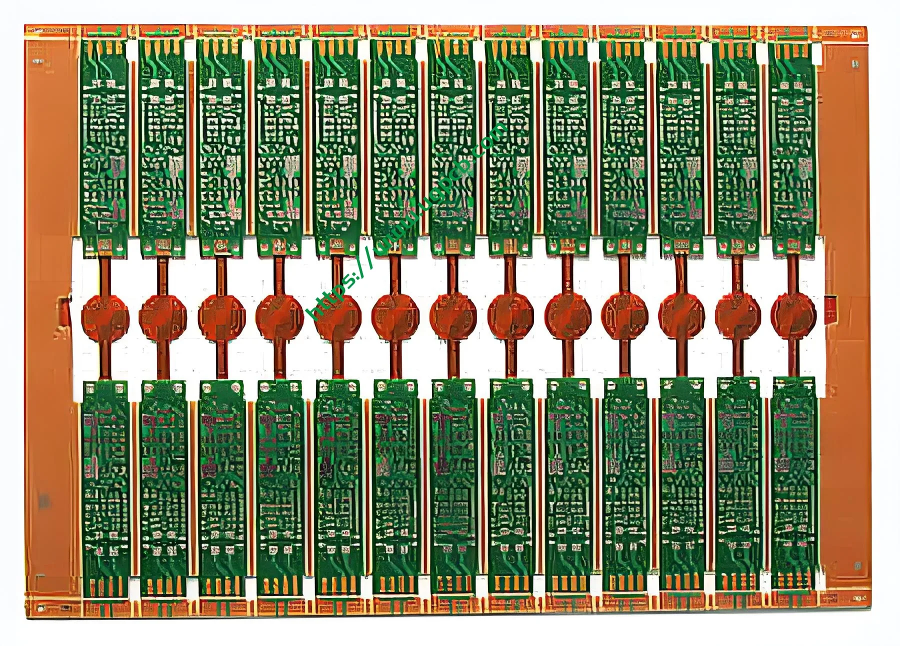
1. Prezentare generală a produsului: Technology Trends in Rigid-Flex PCBs
The PCB rigid-flex combines rigid board strength with flexible circuit adaptability. Market data shows the global rigid-flex PCB market reached RMB 19.061 miliarde in 2026. It will reach RMB 27.545 miliarde de 2033, crescând la a 5.40% CAGR. This growth comes from aerospace, dispozitive medicale, electronice auto, și electronice de consum. These sectors need high-density interconnect (HDI) and 3D space optimization.
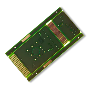
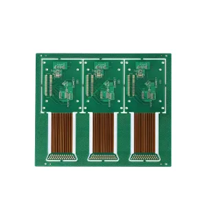
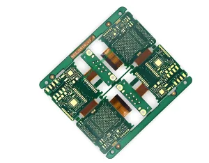
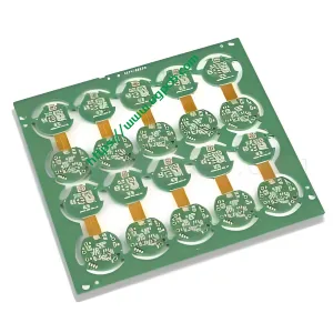
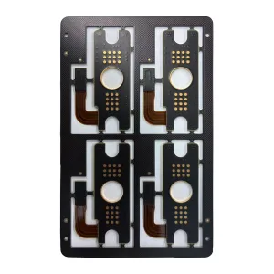
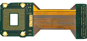
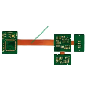
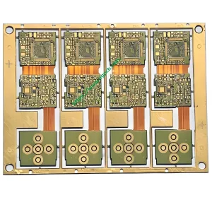
UGPCB leverages over ten years of manufacturing experience. We follow IPC-6013E for flexible and rigid-flex board qualification. Our 1L+1L rigid-flex PCB uses an FR4+PI composite core. It supports prototype to mass production. This product leads in dynamic bend life, fine-line processing, and plated through-hole (PTH) metalizare. It is an ideal interconnect carrier for high-performance electronic devices.
2. Definition and Classification of Rigid-Flex PCBs
2.1 Definiţie
O PCB rigid-flex integrates rigid and flexible substrates through lamination. The rigid area (FR4) supports high-density componentă plasare. The flexible area (Pi) enables 3D folding and dynamic bending. It replaces traditional board-to-board connectors and wiring harnesses. Conform IPC-2223, rigid-flex multilayer boards can include plated through-holes, micro vias, and blind/buried vias. They can form HDI straturi.
2.2 Clasificarea științifică
Based on bending characteristics, rigid-flex PCBs fall into two categories:
| Tip | Caracteristică | Aplicație tipică |
|---|---|---|
| Flex-to-install (îndoire statică) | One-time or limited bending during assembly or maintenance; fixed after bending | Single-use medical endoscope, aerospace harness integration |
| Dynamic flex type | Continuous cyclic bending during device operation; high-cycle fatigue resistance | Foldable phone hinge, printer printhead, wearable device |
UGPCB’s 1L+1L rigid-flex PCB belongs to the dynamic flex type. Its flexible area uses precision lamination and stress optimization. It withstands over 100,000 curbe dinamice (meeting IPC-6013D Class 3). This ensures long-term reliability for demanding applications like consumer and automotive electronics.
3. Principiul de lucru: Interconnection Mechanisms
Two key mechanisms enable rigid-flex PCB operation: stress relief at the rigid-flex interface and electrical interconnection through plated holes.
3.1 Stress Relief at the Rigid-Flex Transition Zone
FR4 and PI have different coefficients of thermal expansion (Cte) and elastic moduli. FR4’s CTE is 14–17 ppm/°C (X-Y direction). PI’s CTE is 12–16 ppm/°C. Under thermal cycling, they generate different thermal stresses. UGPCB uses stepped openings and low-flow prepreg. This gradually thins the rigid layer in the transition area. It spreads peak stress over a larger zone, avoiding single-interface stress concentration.
3.2 Mechanical Design Rules for Bend Area
IPC-2223 states that the minimum bend radius for dynamic applications must follow:
R ≥ 6T
where R = minimum bend radius, T = total thickness of flexible area. For dynamic use, set R to 6–10 times T. When R reaches 100T, dynamic bend life can exceed 1 milioane de cicluri. This satisfies foldable phone requirements.
3.3 Electrical Interconnection via Plated Holes
Găuri traversante placate (PTH) and microvias provide layer-to-layer connections. Copper electroplating grows uniformly on hole walls, creating low-impedance paths. IPC-TM-650 2.1 requires resistance between vias ≤ 0.5Ω. Minimum insulation resistance ≥ 100MΩ. Dielectric strength must pass 1500VAC testing.
4. Technical Parameters and Performance Specifications
4.1 Parametri cheie
| Parametru | Caietul de sarcini | Standard |
|---|---|---|
| Model | PCB rigid-flex, 1L rigid + 1L flexibil | IPC-6013E |
| Material de bază | FR4 (rigid) + PI polyimide (flex) | IPC-4101 / IPC-4204 |
| Stivuire de straturi | 1 rigid layer + 1 flexible layer | - |
| Grosime terminată | 1.6mm | Clasa IPC-6012 3 |
| Grosimea foliei de cupru | 2Oz (~70μm) | IPC-4562 |
| Finisaj de suprafață | De acord, 2μ-inch gold (~0.05μm) | IPC-4552 / Clasa IPC-6012 3 |
| Diametrul minim al găurii | 0.2mm | IPC-2223 |
| Lățimea/Spațiul minim de linie | 3Mii/3mil (~76μm) | IPC-2223 Class 3 |
| Proces special | Astupare cu rasina + copper cap plating | IPC-4761 Type VI |
*Sursa datelor: IPC-6013E, IPC-4562, IPC-4552. The 2μ-inch gold thickness meets IPC-4552 Class 2/3 ENIG recommendations.*
4.2 Performance Advantages of FR4+PI Composite
FR4 (rigid) properties per IPC-4101:
-
Constanta dielectrică (DK): 4.2–4,8 (1MHZ)
-
Factor de disipare (Df): 0.015–0,025
-
Temperatura de tranziție a sticlei (TG): 130–140°C (standard FR4); high-Tg type >170° C.
-
Conductivitate termică: 0.25–0.35 W/m·K
-
Evaluare de inflamabilitate: UL94 V-0
Pi (flexibil) properties per IPC-4204:
-
DK: 3.2–3.6 (1MHZ)
-
Df: 0.002–0.005
-
TG: ≥260°C
-
Elongation at break: ≥50%
-
Short-term temperature resistance: >300° C.
PI performs much better at high temperatures than FR4. FR4’s Tg is ~120°C, and even high-performance FR4 reaches only 180–190°C. PI’s Tg exceeds 260°C. PI also offers good flexibility, copper peel strength, rezistenta chimica, and dimensional stability in high-temperature uses. Cu toate acestea, PI absorbs more moisture (despre 1.6%) than FR4. Control humidity during lamination and storage.
4.3 2OZ Thick Copper for High Current Capacity
2OZ cupru (≈70μm) carries about twice the current of 1OZ (≈35μm). Pentru IPC-2221, a 1mm wide trace with 2OZ copper handles 5–6A at 10°C temperature rise. This suits power management modules and power electronics. UGPCB uses rolled annealed copper. It provides excellent bend fatigue life in the flexible area, depăşind 100,000 dynamic cycles.
4.4 Finisaj de suprafață ENIG
De acord (Imersie de aur cu nichel electroless) has a 2μ-inch gold thickness (~0.05μm). Beneficiile includ:
-
Lipibilitate excelentă: Gold protects nickel from oxidation, ensuring reliable SMT soldering.
-
High flatness: Suitable for fine-pitch BGA and QFP packages.
-
Strong corrosion resistance: Gold is chemically inert, preventing oxidation during long-term storage.
-
Compliant with IPC-4552: Nickel thickness ≥3μm, gold thickness 0.05–0.1μm.
[Imagine: Micrograph of ENIG surface showing uniform gold layer over nickel]
ALT tag: ENIG surface finish cross-section with 2μ-inch gold layer on nickel for rigid-flex PCB
5. Precision Circuit Processing: 3mil/3mil Line and 0.2mm Microvia
5.1 3mil/3mil Line Width/Space Capability
Our product achieves 3mil (≈76μm) lățimea și spațiul minim de linie. This falls under HDI. IPC-6013E Class 3 for high reliability requires a minimum tolerance of 50μm (~2mil). Our 3mil/3mil accuracy fully meets high-reliability rigid-flex PCB manufacturing requirements.
UGPCB uses these technologies:
-
Imagistica directă laser (Ldi): Imaging accuracy ±15μm, eliminating film expansion/shrinkage errors.
-
Precision etching control: Etching factor ≥3.0, line width tolerance ≤±15%.
-
Aoi 100% inspecţie: Automated optical inspection covers >99.9% of the panel.
5.2 0.2mm Microvia Drilling
Minimum hole diameter is 0.2mm (~8mil). This meets HDI rigid-flex board needs. Noi folosim CNC mechanical drilling or a CO₂/UV laser combination to handle various hole sizes.
6. Proces special: Blocaj cu rășină + Copper Cap Plating
6.1 Prezentare generală a procesului
We use the “resin plugging + copper cap plating” combination. This is IPC-4761 Type VI: Filled and Capped. Primul, fill the via with resin and cure it. Then plate copper over the surface. This creates a completely flat via surface. It is widely used in HDI and plăci rigid-flex.
6.2 Process Steps
-
Foraj – Drill target-diameter vias in copper-clad laminate.
-
Cupru electroless + placare cu panouri – Deposit thin copper on hole walls, then thicken by panel plating.
-
Astupare cu rasina – Use vacuum plugging equipment to fill vias with low-shrinkage resin.
-
Vindecare – Bake at 150–170°C to fully harden the resin.
-
Grinding – Remove excess resin from board surface to make vias flush with the surface.
-
Copper cap plating – Electroplate a copper layer over the ground resin surface to ensure solderability and conductivity.
6.3 Advantages and Value
Compared to solder mask plugging or ink plugging, this process offers:
-
Planeitate excelentă: Height tolerance after grinding ≤ ±20μm, suitable for BGA and fine-pitch components.
-
Fiabilitate ridicată: Resin filling plus copper cap prevents “popcorning” sau “blow holes” during soldering.
-
Increased routing density: You can route traces over plugged vias, greatly improving HDI board utilization.
-
Strong thermal stress resistance: Cured resin CTE (25–40 ppm/°C) matches FR4, reducing cracking under thermal cycles.
7. Procesul de fabricație: UGPCB’s Full Quality Control
UGPCB monitors every step of 1L+1L rigid-flex PCB production. All processes comply with Standardele IPC.
-
IQC incoming inspection – FR4 per IPC-4101; PI flex copper-clad laminate per IPC-4204; copper foil per IPC-4562.
-
Circuitul stratului interior – Flexible layer pattern transfer → etching → AOI.
-
Laminare – Press FR4 and PI layers with low-flow prepreg at high temperature and pressure.
-
Foraj – CNC mechanical drilling (0.2mm min.) + foraj cu laser (opțional).
-
Metalizarea PTH – Electroless copper + placare cu panouri. Hole wall copper meets IPC-6012 Class 3.
-
Astupare cu rasina + copper cap plating – Per IPC-4761 Type VI.
-
Circuitul stratului exterior – LDI → pattern plating → etching → AOI 100%.
-
Finisaj de suprafață - DE ACORD, 2μ-inch gold, pentru IPC-4552.
-
Profilare – Precision die punching or CNC routing. Flexible area contour tolerance ±50μm.
-
Test electric – Sondă zburătoare or universal grid fixture. 100% continuity test.
-
Reliability tests – Bend cycle (IPC-TM-650 2.4.3), thermal cycle (–55°C to 125°C, 1000 cicluri), high temperature/humidity (85°C/85% RH, 1000 ore).
-
FQC final inspection + packaging and shipping.
8. Quality and Reliability Verification Based on IPC Standards
8.1 IPC-6013 Performance Classes
IPC-6013 defines three classes for rigid-flex boards:
| Clasă | Aplicație | Toleranța defectelor | UGPCB Suitability |
|---|---|---|---|
| Clasă 1 – General electronic | Electronica de consum, Iot, jucării | Cosmetic defects allowed | Basic option |
| Clasă 2 – Dedicated service | Control industrial, auto, telecom | Moderate defect control | Standard option |
| Clasă 3 – High reliability | Aerospațial, medical, militar | Defecte aproape de zero, trasabilitate deplină | Our product meets this |
UGPCB’s 1L+1L rigid-flex PCB satisfies all performance requirements of IPC-6013D/E Class 3.
8.2 Bend Life Test (IPC-TM-650 2.4.3)
This test uses a 0.5mm radius bending fixture. It performs 180° reciprocating bends at 30–60 cycles per minute. UGPCB’s flexible area survives >100,000 dynamic bends with no circuit damage. This meets IPC-6013D Class 3 for high-reliability dynamic applications. The industry’s best designs can exceed 1 million cycles when the bend radius increases to 100T.
8.3 Thermal Cycle Test
Per IPC-TM-650 2.6.7.2, samples undergo 1000 cycles from –55°C to 125°C. Each cycle has a 15-minute dwell time. Transfer time does not exceed 5 minute. După testare, cross-section analysis shows no cracks in the hole wall copper and no resin delamination. This confirms the thermomechanical reliability of the FR4-PI lamination interface.
8.4 High Temperature/Humidity Bias Test (85°C/85% RH)
Per IPC-TM-650 2.6.3.3, samples sit at 85°C and 85% relative humidity with bias for 1000 ore. The insulation resistance changes by less than one order of magnitude. No significant conductive anodic filament (Caf) formation occurs. This verifies the long-term electrical stability of FR4 and PI in humid environments.
9. Scenarii de aplicație și cazuri de utilizare
9.1 Aerospațial
Rigid-flex PCBs are ideal for aerospace electronics because they save weight and space and resist high vibration. Utilizări tipice: satellite deployable antennas, onboard flight computers, sisteme de ghidare a rachetelor. IPC-6013DS aerospace-grade standards demand strict material traceability and reliability.
9.2 Dispozitive medicale
In endoscopes, implantable devices, and wearable health monitors, rigid-flex PCBs combine signal transmission with mechanical movement thanks to >10,000 dynamic bend cycles and high-density integration.
9.3 Electronica de consum
Smartphone-uri pliabile, AR/VR glasses, laptop hinge connections – rigid-flex PCBs can achieve bend radii as low as 1mm, enabling ultra-thin foldable designs. Foldable phone hinges typically use 1L or 2L rigid-flex boards requiring 100,000–200,000 dynamic bend cycles. Our product fully meets this requirement.
9.4 Electronică auto
Advanced driver-assistance systems (ADAS), module pentru camere auto, millimeter-wave radar sensors – rigid-flex PCBs withstand –40°C to +150°C extremes and meet AEC-Q200 automotive grade. They support high-frequency applications like 77GHz radar.
9.5 Control industrial
Robot joint controllers, industrial camera flexible connections, servo drives – rigid-flex PCBs replace traditional wiring harnesses and connectors. This reduces system BOM cost by 45% while improving mechanical reliability.

10. Why Choose UGPCB’s Rigid-Flex PCB?
10.1 Rezumatul avantajelor tehnice
-
✅ FR4+PI composite – balances cost and performance for rigid-flex needs.
-
✅ 2OZ thick copper – high current capacity for power circuits.
-
✅ 3mil/3mil precision lines – high-density routing for complex circuits.
-
✅ 0.2mm microvias + resin plugging + copper cap – flat via surface supports BGA assembly.
-
✅ >100,000 dynamic bend life (Clasa IPC-6013D 3).
-
✅ ENIG finish (2μ-inch gold) – excellent solderability and storage life.
-
✅ IPC-6013E Class 3 compliance – aerospace, medical, military-grade reliability.
-
✅ 1.6mm finished thickness – standard thickness compatible with mainstream SMT lines.
10.2 Full-Process Service Commitment
UGPCB provides end-to-end support: Gerber review → DFM analysis → prototyping → mass production → PCBA one-stop service. Promitem:
-
Fast prototyping: 1L+1L rigid-flex PCB samples in 5–7 working days.
-
100% testarea electrică: Every product undergoes flying probe or fixture testing before shipment.
-
Complete shipment reports: Includes cross-section analysis, bend life test report, thermal cycle test report, impedance test report, and UL certificate.
11. Get a Quote and Technical Support
UGPCB delivers high-performance rigid-flex PCB solutions to global customers. Whether you are in proof-of-concept or need high-volume production, our engineering team provides customized design optimization and DFM review based on your specific needs.
Contact us for a quote or technical consultation:
-
🌐 Site web: www.ugpcb.com
-
📧 E-mail: sales@ugpcb.com
-
📞 Phone/WhatsApp/WeChat: +86-19072115165
Act now! Email your Gerber files and design requirements. UGPCB engineers will provide a DFM review report and competitive quote within 4 ore. UGPCB – Your professional partner for high-performance rigid-flex PCBs.