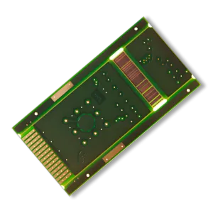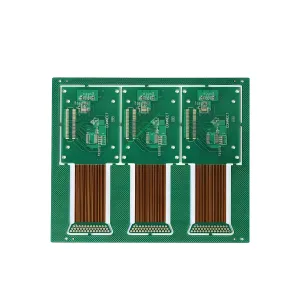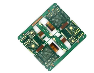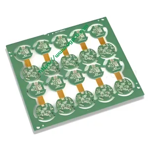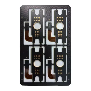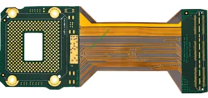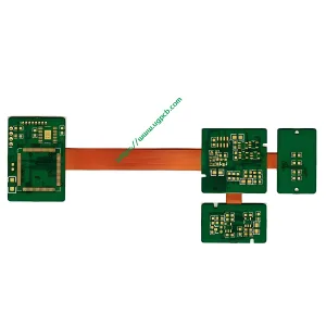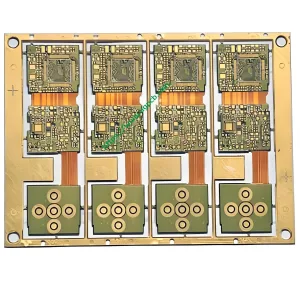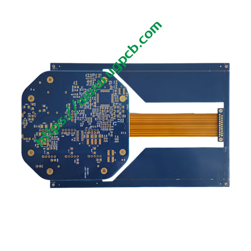
Prezentare generală a produsului: Ce este un PCB Rigid-Flex?
Modern electronic products demand lightweight designs, multifunctionality, și fiabilitate ridicată. Engineers face a common challenge: how to implement complex circuitry within a limited space while ensuring mechanical reliability and signal integrity. UGPCB’s Blue Solder Mask 4-Layer Rigid-Flex PCB solves this challenge. It offers a high-integration interconnect solution.
A Rigid-Flex PCB combines rigid circuit board material with flexible circuit material through a precision lamination process. Conform IPC-2223 (Sectional Design Standard for Flexible/Rigid-Flexible Printed Boards) and IPC-6013 (Qualification and Performance Specification for Flexible and Rigid-Flexible Printed Boards), a Rigid-Flex PCB has three defining features: rigid and flexible materials together, trei sau mai multe straturi conductoare, and plated through holes. The IPC standard classifies Rigid-Flex PCBs as Tip 4.
UGPCB’s Blue Solder Mask 4-Layer Rigid-Flex PCB uses FR-4 epoxy glass laminate in rigid areas and polyimide (Pi) film in flexible areas. A unified lamination process bonds these materials seamlessly, creating a structure that remains rigid where needed and bends where required.
Product Specifications and Technical Parameters
The following table lists the core technical specifications of UGPCB’s Blue Solder Mask 4-Layer Rigid-Flex PCB.
| Parametru | Caietul de sarcini |
|---|---|
| Product Model | Blue Solder Mask Rigid-Flex PCB (R-FPCB) |
| Combinație de materiale | FR-4 + Pi |
| Număr de straturi | 4 Straturi |
| Culoarea măștii de lipit | Albastru / Alb |
| Grosime terminată | 0.6 mm |
| Grosime de cupru | 0.025 mm (aproximativ. 0.7 Oz) |
| Tratament de suprafață | Aur de imersiune (De acord) |
| Lățimea minimă a liniei / Spațiere | 0.1 mm |
| Aplicație | Communication Digital Equipment |
The FR-4 rigid section thickness typically ranges from 0.2 mm la 1.6 mm. This provides stable mechanical support for component mounting. The PI flexible section thickness ranges from 0.025 mm la 0.1 mm. This enables bendable interconnect functionality.
Definiția produsului: Integrated Interconnect Precision Structure
From a structural definition perspective, UGPCB’s Rigid-Flex PCB combines a flexible printed circuit (FPC) with a rigid printed circuit board (PCB) through lamination. This creates a board that exhibits both FPC and PCB characteristics. Zonele rigide (FR-4 sections) provide mechanical support and a component placement platform. Flexible areas (PI sections) connect rigid sections together. They also allow the PCB to bend and flex, enabling 3D spatial configuration and three-dimensional interconnect architecture.
UGPCB’s Rigid-Flex PCB is manufactured as a single integrated unit, unlike simple stiffener attachments on a flexible board. Rigid and flexible sections share the same copper layers. The precision lamination process bonds these layers together, with copper traces extending continuously from rigid sections into flexible sections. This one-piece design provides electrical continuity and mechanical reliability unmatched by any connector or cable solution.
Clasificarea produselor: A Scientific Classification System for Rigid-Flex PCBs
The IPC-2223 standard defines a multi-dimensional classification system for Rigid-Flex PCBs.
După tipul structural
-
Tip 1: Single-sided flexible area + single-sided rigid area
-
Tip 2: Double-sided flexible area + double-sided rigid area
-
Tip 3: Multilayer flexible area + multilayer rigid area
-
Tip 4: Multilayer rigid-flex composite structure (UGPCB’s product falls into this category)
După numărul de straturi
-
2-4 straturi (UGPCB’s product has 4 straturi, belonging to this category)
-
6-8 straturi
-
10+ layers for high-density applications
După scenariul de aplicare
-
Static Bending: The board bends once during installation and does not flex repeatedly during use
-
Dynamic Bending: The board flexes repeatedly during device operation, such as in foldable screen phones
-
Fixed Mounting: Rigid areas handle primary functions while flexible areas serve internal interconnect needs
UGPCB’s Blue Solder Mask 4-Layer Rigid-Flex PCB belongs to Type 4 multilayer composite structures. It primarily serves fixed-mount and static-bending scenarios in communication digital equipment.
Materiale: FR-4 and PI – The Golden Combination
Material selection forms the foundation of Rigid-Flex PCB design. It directly affects mechanical reliability, performanta termica, și proprietăți electrice. UGPCB’s Blue Solder Mask 4-Layer Rigid-Flex PCB uses the classic FR-4 + PI material combination.
Material de zonă rigidă: FR-4
FR-4 epoxy glass fabric laminate serves as the rigid area material. This flame-retardant epoxy-based composite offers:
-
Rezistență mecanică ridicată – FR-4 provides stable mechanical support for precision components such as ICs and batteries
-
Izolație electrică excelentă – Its dielectric constant (DK) ranges from 4.2 la 4.7, meeting standard signal transmission requirements
-
Eficacitatea costurilor – FR-4 is the most widely used and mature substrate material in the rigid PCB industry
-
Compatibilitate cu procese – FR-4 works seamlessly with standard PCB manufacturing processes
Material pentru zonă flexibilă: Poliimidă (Pi)
Polyimide film serves as the flexible area material. This is the most common thermosetting insulation material used in flexible circuit manufacturing. Its thickness typically ranges from 12.5 μm la 125 μm. UGPCB’s product uses PI film thickness between 0.025 mm și 0.1 mm.
PI material offers outstanding properties:
-
Rezistență ridicată la căldură – Withstands lead-free soldering temperatures above 260°C
-
Excellent flexibility – Survives over 100,000 bending cycles without fracture
-
Superior insulation – Effectively prevents circuit shorting
-
Stable dielectric performance – Dielectric constant approximately 3.4 la 3.5
Selecția foliei de cupru
UGPCB’s product uses 0.025 mm copper foil thickness. In material selection strategy, flexible areas typically use Laminat Recoacet (RA) Cupru due to its superior ductility. It resists fracture during bending. Rigid areas use Electrodepus (ED) Cupru to meet conductivity and mechanical strength requirements. This zone-specific material selection ensures reliability in bendable areas and electrical performance in rigid areas.
Adhesive and Bonding Materials
Bonding between rigid and flexible layers depends on acrylic or epoxy adhesives. These must provide sufficient bond strength and flexibility to prevent delamination during bending or thermal cycling. UGPCB uses high-precision adhesive application processes. Film thickness uniformity is controlled within ≤5 μm tolerance, ensuring consistent lamination quality.
Ghid de proiectare: Engineering Principles Per IPC Standards
Rigid-Flex PCB design is far more complex than rigid PCB design. It must meet mechanical and electrical requirements for both rigid and flexible sections. The following design guidelines are based on IPC-2223.
Bend Radius Design
Bend radius is the most critical mechanical parameter in Rigid-Flex PCB design. Conform IPC-2223:
-
Static Bending: Minimum bend radius should be 6 la 12 times the total flexible layer thickness
-
Dynamic Bending: Minimum bend radius must exceed 100 times the flexible layer thickness to achieve a dynamic bending life exceeding 1 milioane de cicluri
The bend radius formula is: R_min = k × t
Unde:
-
R_min = minimum bend radius
-
t = total flexible layer thickness (folie de cupru + substrat PI)
-
k = safety factor (6-12 for static bending, 100 pentru îndoire dinamică)
De exemplu, if the flexible area has a PI substrate thickness of 25 μm and copper thickness of 12 μm, the dynamic bending minimum radius should be ≥ 3.7 mm.
Impedance Control and Signal Integrity
Impedance matching is crucial for high-frequency, high-speed applications. UGPCB’s Rigid-Flex PCBs achieve impedance tolerance controlled within ±5% . The relationship between signal transmission speed and dielectric constant follows this formula:
v = c / √εr
Unde:
-
v = signal transmission speed
-
c = speed of light in vacuum (approximately 3×10⁸ m/s)
-
εr = constanta dielectrică
PI material has a dielectric constant around 3.5. Signal transmission speed is approximately 1.6×10⁸ m/s, suitable for conventional high-frequency applications.
Transition Zone Design
A buffer zone of at least 1.5 mm must be reserved at the junction between rigid and flexible areas to avoid stress concentration. Trace ends should include teardrop-shaped pads to distribute peak stress. The coverlay opening width in the bending area should exceed the bending arc length to prevent film wrinkling.
Principii de rutare
Traces in flexible areas require even distribution and should not be overly dense. All corners should be designed with arcs (radius ≥ 0.2 mm) to reduce stress concentration. The routing direction should be perpendicular to the bending axis whenever possible. This reduces stress by up to 30%.
Principiul de funcționare: Signal Transmission and Mechanical Function
The operating principle of a Rigid-Flex PCB can be understood from two perspectives: electrical signal transmission and mechanical structural function.
Electrical Operating Principle
A Rigid-Flex PCB functions as a multilayer interconnect structure. Its core purpose is to enable electrical connections between different areas of the circuit board. Circuits in rigid areas achieve electrical continuity with circuits in flexible areas through plated through holes (PTH). Signals transmit seamlessly between FR-4 rigid layers and PI flexible layers. Because the entire system is manufactured as an integrated unit, signal transmission does not require connectors or cables. Signal integrity is better preserved in high-speed signal transmission scenarios with proper impedance matching.
Mechanical Operating Principle
In terms of mechanical structure, rigid areas provide fixed component mounting platforms and mechanical support. This ensures stable positioning of electronic components within the device. Flexible areas act as bridges connecting different rigid areas. They also allow the entire PCB system to bend and fold in three-dimensional space, adapting to compact internal device layouts.
Lamination Process Principle
The core of Rigid-Flex PCB technology lies in the lamination process. Rigid substrates (FR-4), flexible substrates (Pi), and prepreg (epoxy resin bonding film) are pressed together under high temperature and high pressure. Lamination temperature is controlled at 170-180°C, pressure at 2-3 MPA, and duration at 60-90 minute. După laminare, the PCB undergoes a stress-relief bake at 120°C for 2 ore. This releases internal stresses and prevents warpage during subsequent processing.
Caracteristicile produsului: Ten Core Advantages of Rigid-Flex PCBs
UGPCB’s Blue Solder Mask 4-Layer Rigid-Flex PCB combines the advantages of rigid PCBs and flexible FPCs. It offers the following ten core features:
-
Space Savings – Rigid-Flex PCBs replace traditional rigid board + conector + cable assemblies. They reduce weight by 60-75% compared to rigid board + cable solutions. Their 3D layout enables more complex circuits within limited space.
-
Improved Connection Reliability – Removing board-to-board connectors and cables eliminates a common failure point (connector contact issues). This significantly improves system reliability.
-
Asamblare simplificată – Fewer components and assembly steps reduce assembly costs by 15-25% compared to traditional rigid board + wiring harness designs.
-
Excellent Vibration and Shock Resistance – Flexible sections effectively absorb and dissipate mechanical stress, preventing connection fractures caused by vibration.
-
Integritate superioară a semnalului – Without connectors and cables, signal transmission has better impedance matching and less signal reflection.
-
3D Assembly Capability – The board can bend, pliază, and roll, adapting to various complex 3D spatial configuration requirements.
-
Rezistență la temperaturi ridicate – PI material withstands lead-free soldering temperatures above 260°C.
-
Customizable Solder Mask Colors – Blue/white solder mask options meet different application needs for visual identification and light management.
-
Thin Profile Design – The finished thickness is only 0.6 mm, suitable for lightweight, thin electronic products.
-
High Precision Manufacturing – Minimum line width/spacing reaches 0.1 mm, meeting high-density interconnect requirements.
Structura produsului: Layer Stackup Analysis of the 4-Layer Rigid-Flex PCB
The typical layer stackup structure of UGPCB’s Blue Solder Mask 4-Layer Rigid-Flex PCB (de sus în jos) este după cum urmează:
-
Masca de lipit de sus: Blue solder mask ink, protects top circuits and prevents oxidation
-
Top Circuit Layer (L1) : Grosime de cupru 0.025 mm
-
Insulating Dielectric Layer: FR-4 epoxy resin (zonă rigidă) / PI film (zonă flexibilă)
-
Inner Circuit Layer (L2) : Grosime de cupru 0.025 mm
-
Insulating Core Layer: FR-4 epoxy resin / PI film
-
Inner Circuit Layer (L3) : Grosime de cupru 0.025 mm
-
Insulating Dielectric Layer: FR-4 epoxy resin (zonă rigidă) / PI film (zonă flexibilă)
-
Bottom Circuit Layer (L4) : Grosime de cupru 0.025 mm
-
Mască de lipit de jos: Blue/white solder mask ink
-
Tratament de suprafață: Aur de imersiune (De acord)
Copper traces in rigid and flexible areas extend continuously. They achieve seamless electrical connection in the rigid-flex transition zone. Rigid areas use plated through holes (PTH) for interlayer interconnection.
Specificații de performanță: Quality Assurance Per IPC-6013
The key performance specifications of UGPCB’s Blue Solder Mask 4-Layer Rigid-Flex PCB meet IPC-6013 Class 2 / Clasă 3 cerințe.
| Parametru de performanță | Caietul de sarcini / Standard | Standard de referință |
|---|---|---|
| Interval de temperatură de funcționare | -40°C to +105°C | IPC-6013 |
| Rezistenta la caldura de lipit | 260° C. / 10 secunde | IPC-TM-650 |
| Rezistenta de izolare | ≥ 100 MΩ | IPC-6013 |
| Characteristic Impedance Tolerance | ±10% (standard) / ± 5% (precizie) | IPC-2223 |
| Registration Accuracy | ±25-50 μm | IPC-6013 |
| Coajă de rezistență | ≥ 0.8 N/mm | IPC-TM-650 |
| Solder Mask Adhesion | Meets IPC-SM-840 | IPC-SM-840 |
| Static Bending Life | Peste 1 milioane de cicluri | Meets IPC-2223 |
*Surse de date: IPC-6013 Qualification and Performance Specification for Flexible and Rigid-Flexible Printed Boards, IPC-TM-650 Test Methods Manual*
Procesul de fabricație: Eight Core Process Steps
Rigid-Flex PCB manufacturing is over 30% more complex than conventional PCB manufacturing. Precision requirements are 2-3 times tighter. UGPCB strictly follows these eight core process steps.
Pas 1 – Substrate Preparation
-
PI substrate treatment: Plasma cleaning removes surface oils. Micro-etching roughens the surface to enhance adhesion.
-
FR-4 substrate treatment: Baking at 100-120°C for 2-4 hours releases internal stress.
-
Adhesive film treatment: Thickness uniformity is controlled (error ≤5 μm). Pre-baking removes moisture.
Pas 2 – Flexible Area Circuit Fabrication
Laser cutting or etching processes create circuit patterns on the copper foil of the PI substrate. Minimum trace width reaches 25 μm. Trace edges are smooth and burr-free. Coverlay adhesion is ≥ 0.8 N/mm.
Pas 3 – Rigid Area Circuit Fabrication
Pattern transfer processes achieve line width/spacing precision controlled at ±10 μm (traditional rigid boards have ±20 μm). Rigid areas reserve connection pads for flexible areas. Pad positioning precision is controlled at ±5 μm.
Pas 4 – Lamination Bonding
Rigid substrates, flexible substrates, and prepreg are pressed together under high temperature and high pressure. Temperatură: 170-180° C., presiune: 2-3 MPA, duration: 60-90 minute. A silicone rubber cushion sits beneath the flexible section during pressing.
Pas 5 – Drilling
Rigid areas use mechanical drilling. Flexible areas require laser drilling to avoid mechanical stress damage. Laser drilling achieves minimum hole diameter of 0.1 mm.
Pas 6 – Electroless Copper Deposition and Plating
An electroless copper deposition process deposits a conductive copper layer on hole walls, enabling interlayer interconnection. Copper deposition thickness uniformity is controlled to ensure reliable through-hole connections.
Pas 7 – Pattern Transfer and Etching
The outer layer circuit pattern is created. Gravarea îndepărtează cuprul nedorit, leaving the final circuit pattern.
Pas 8 – Surface Treatment and Final Profiling
-
Aur de imersiune (De acord) : Primul, a nickel layer is plated on copper surfaces (to block copper diffusion). Then a gold layer is deposited (for oxidation protection). This keeps the circuit board surface flat and stable, suitable for precision component mounting and multiple reflow soldering cycles.
-
Final Profiling: Precision milling cutters shape the board to final dimensions, ensuring profile accuracy.
Scenarii de aplicație: The Ideal Choice for Communication Digital Equipment
UGPCB’s Blue Solder Mask 4-Layer Rigid-Flex PCB is widely used in the following scenarios due to its high reliability, profil subțire, and space-saving features.
Communication Digital Equipment – This is the core application area for this product. În stațiile de bază 5G, optical transmission network equipment, and WiMax base stations, Rigid-Flex PCBs can replace numerous cables. De exemplu, one WiMax base station replaced 75 cables with Rigid-Flex PCBs, achieving significant cost savings and space optimization.
Mobile Communication Terminals – Suitable for smartphones, tablete, and other mobile devices that demand high space utilization efficiency.
Portable Electronic Devices – Suitable for smart watches, dispozitive purtabile, portable medical instruments, and other products requiring lightweight, thin designs.
Test and Measurement Instruments – Suitable for equipment requiring precision interconnects and space optimization.
Sisteme de control industrial – Suitable for industrial automation and control equipment requiring high-reliability interconnects.
Tendințele pieței: Rapid Growth of the Rigid-Flex PCB Market
According to market research data, the global Rigid-Flex PCB market is growing rapidly. The global Rigid-Flex PCB market size was approximately $2.462 billion USD in 2025. It is projected to reach $3.471 billion USD by 2032, cu o rată de creștere anuală compusă (CAGR) de 5.1%. Another study shows the SSD Rigid-Flex PCB market has a CAGR as high as 8.84%. This growth trend is driven by strong demand for high-integration interconnect solutions in 5G communication equipment, Electronica de consum, electronice auto, și dispozitive medicale.
Why Choose UGPCB’s Blue Solder Mask 4-Layer Rigid-Flex PCB?
-
Capacitate de producție de precizie – Minimum line width/spacing of 0.1 mm meets high-density interconnect requirements
-
Control strict al calității – Full-process compliance with IPC-6013 and IPC-2223 standards
-
Mature Process Experience – The FR-4+PI material combination has been validated through extensive project experience
-
Customization Services – Blue/white solder mask options available for different application needs
-
Suport tehnic profesional – One-stop service from design review to mass production
Obțineți o cotație astăzi
The UGPCB team is ready to provide professional Rigid-Flex PCB solutions for your project. Please provide the following information for a fast quote:
-
Rigid-Flex PCB layer count, dimensiuni, and outline requirements
-
Detailed dimensions for rigid and flexible areas
-
Minimum line width/spacing and copper thickness requirements
-
Surface treatment type (De acord, OSP, etc.)
-
Solder mask color selection (blue/white)
-
Expected order quantity
Contactaţi-ne:
📧 E-mail: sales@ugpcb.com
🌐 Site web: www.ugpcb.com
📞 Tel: +86-755-XXXXXXXX
Let UGPCB’s professional team provide the most reliable Rigid-Flex PCB solution for your electronic products!
References and Standards
The technical data, linii directoare de proiectare, and performance specifications cited in this document come from the following authoritative sources:
-
IPC-2223E: Sectional Design Standard for Flexible/Rigid-Flexible Printed Boards (IPC – Association Connecting Electronics Industries)
-
IPC-6013E: Qualification and Performance Specification for Flexible and Rigid-Flexible Printed Boards (IPC – Association Connecting Electronics Industries)
-
IPC-2221: Standard generic pentru designul plăcii imprimate (IPC – Association Connecting Electronics Industries)
-
IPC-TM-650: Manualul metodelor de testare (IPC – Association Connecting Electronics Industries)
-
IPC-SM-840: Qualification and Performance Specification for Permanent Solder Mask (IPC – Association Connecting Electronics Industries)
-
Market data sources: QY Research, DIResearch, and other industry research organizations’ Rigid-Flex PCB market analysis reports