


Présentation du produit
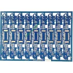
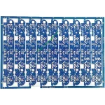
L'UGPCB présente le PCB de commande de moteur de robot, un double face haute fiabilité circuit imprimé conçu spécifiquement pour les systèmes de contrôle de mouvement robotisés. Ce produit utilise le stratifié de tissu de verre époxy recouvert de cuivre Kingboard KB6160A et suit strictement les exigences de la spécification IPC-4101E/21.. Le matériau offre une excellente résistance thermique, résistance mécanique, et performances électriques. Ces qualités constituent une base matérielle solide pour les applications de commande et de commande de moteurs robotiques..
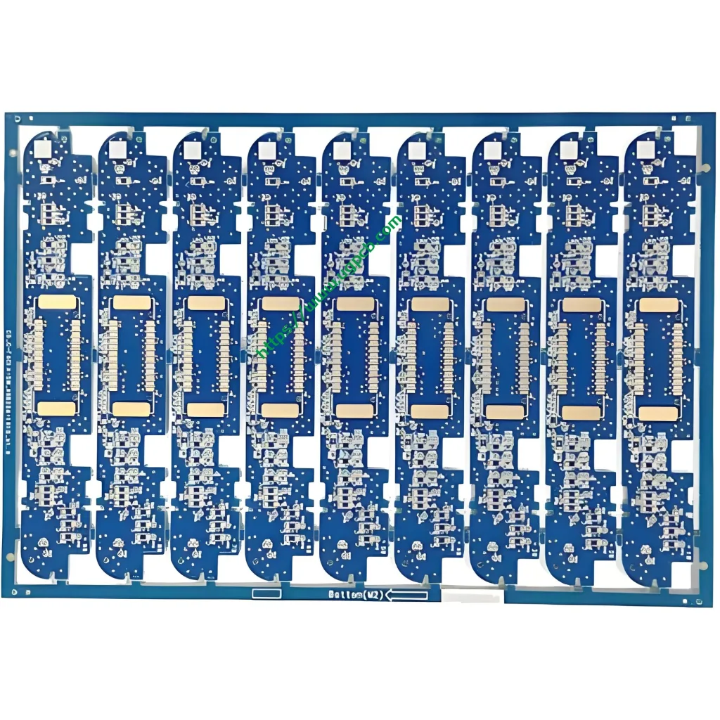
Cecarte de commande de moteur de robot mesures 96.83 × 30.6 mm avec un 1.6 mm épaisseur du panneau. Il présente une structure de câblage double face (2 couches) qui répond aux exigences d'espace des systèmes de contrôle robotiques compacts. Le produit offre une ouverture minimale de 0.27 mm, largeur de trace/espacement de 0.32/0.382 mm, et une épaisseur de feuille de cuivre de 35/35 µm (1 oz de cuivre des deux côtés). Le traitement de surface utilise OSP (Conservateurs de soudabilité organique) finition antioxydante. Le masque de soudure est disponible en bleu, et la légende apparaît en blanc.
Définition du produit et conformité aux normes
LePCB de commande de moteur de robot est une carte de circuit imprimé spécialisée pour les entraînements communs robotisés, commande de servomoteur, cartes de contrôle de mouvement, et applications similaires. Ce PCB transmet les signaux d'entraînement du moteur, distribue le pouvoir, et exécute la logique de contrôle. Il fonctionne comme un composant essentiel dans le fonctionnement du robot. “système nerveux.”
Ce produit est fabriqué et conçu en stricte conformité avec les normes internationales suivantes:
- IPC-4101E/21 (Spécification des matériaux de base pour les cartes imprimées rigides et multicouches): Le stratifié KB6160A répond à cette spécification.
- IPC-6012E (Qualification et spécifications de performances pour les cartes imprimées rigides): Cela couvre les exigences de qualification et de performance pour les panneaux double face..
- IPC-A-600K (Acceptabilité des cartes imprimées): Ceci sert de norme d'acceptation illustrée.
- CIB-4555 (Spécification de performance pour les conservateurs organiques de soudabilité à haute température pour cartes imprimées): Ceci régit le processus de finition de surface OSP.
- UL 94 V-0 (Norme d'inflammabilité): Cela représente l'indice de retardateur de flamme le plus élevé.
Source de données: Les informations standard ci-dessus proviennent de l'IPC (Association reliant les industries électroniques) documents standards officiels et UL (Laboratoires souterrains) normes de sécurité.
Faits saillants de conception
Sélection des matériaux – Les principaux avantages du KB6160A
KB6160A est un stratifié cuivré en tissu de verre époxy FR-4 conventionnel de Kingboard Laminates Holdings. Les paramètres de performance clés apparaissent ci-dessous:
| Propriété | Méthode d'essai (IPC-TM-650) | Spécification | Valeur typique |
|---|---|---|---|
| Température de transition du verre (Tg) | 2.4.25 (DSC) | ≥130℃ | 135℃ |
| Contrainte thermique (288℃ Flotteur de soudure) | 2.4.13.1 | ≥10 s | ≥180 s |
| CTE (a1) Axe z | 2.4.24 (Tma) | - | 58 ppm / ℃ |
| CTE (a2) Axe z | 2.4.24 (Tma) | - | 286 ppm / ℃ |
| Température de décomposition thermique (Td) | 2.4.24.6 (TGA) | - | 305℃ |
| Inflammabilité (Indice de flamme) | UL 94 | V-0 | V-0 |
| Résistivité de surface | 2.5.17.1 | ≥1,0×10⁴ MΩ | 1.0×10⁶ MΩ |
| Résistivité du volume | 2.5.17.1 | ≥1,0×10⁶ MΩ·cm | 1.0×10⁸ MΩ·cm |
| Constante diélectrique (@1 MHz) | 2.5.5.2 | ≤5,4 | 4.58 |
| Facteur de dissipation (@1 MHz) | 2.5.5.2 | ≤0,035 | 0.022 |
| Résistance au pelage du cuivre (125℃) | 2.4.8 | ≥0,70 N/mm | 1.70 N/mm |
| Résistance à la flexion (Chaîne) | 2.4.4 | ≥415 N/mm² | 565 N/mm² |
Source de données: Les données ci-dessus proviennent de la documentation technique officielle du produit de Kingboard Laminates Holdings et des normes de méthode de test IPC-TM-650..
Le stratifié KB6160A offre ces caractéristiques essentielles:
- Blocage UVB et compatibilité AOI: Le matériau supporte le blocage de la lumière UV et inspection optique automatique (Zone d'intérêt). Cela améliore l'efficacité et la précision de la production de PCB.
- Excellente stabilité dimensionnelle: Les valeurs de déformation typiques atteignent seulement 0.17%/0.35%, bien en dessous de l'exigence de la norme IPC de ≤1,0 %.
- Performance thermique supérieure: Tg≥130℃ (typique 135 ℃) avec une résistance aux contraintes thermiques de ≥180 secondes à un flotteur de soudure de 288 ℃.
- Propriétés mécaniques exceptionnelles: La résistance à la flexion typique atteint 565 N/mm².
Largeur/espacement des traces et conception de l'ouverture
Ce produit présente une ouverture minimale de0.27 mm et largeur/espacement des traces de0.32/0.382 mm. Selon IPC-2221, la norme de conception de fondations pour tous les documents de la série IPC-2220, la capacité de transport de courant du conducteur suit cette formule:
Je = k × ΔT ^ 0,44 × A ^ 0,725
Où I représente la capacité de charge actuelle (UN), k est le facteur de correction (0.024 pour les couches intérieures, 0.048 pour les couches externes), ΔT est l'augmentation de la température (℃), et A est la section transversale du conducteur (mil²). Pour les conducteurs de couche externe à une élévation de température de 10 ℃, un 0.32 mm largeur de trace (environ 12.6 mil) avec 35 µm (1 once) l'épaisseur du cuivre fournit environ1.2 UN capacité actuelle. Cette conception prend entièrement en charge les exigences de transmission de signaux et d'entraînement à courant modéré pour les applications de commande de moteurs robotiques..
Épaisseur des panneaux et empilement des couches
Le 1.6 mm L'épaisseur du panneau représente l'épaisseur standard pour les panneaux rigides. PCB. Il équilibre la résistance mécanique et les performances électriques. Le double face (2-couche) la structure de câblage permet une séparation efficace des couches de puissance et de signal dans un espace limité. Cela répond aux principes de partition fonctionnelle des circuits de commande de moteur robotique, entraînement par moteur clairement séparé, contrôleur principal, interface du capteur, et modules de gestion de l'énergie.
Principe de fonctionnement
LePCB de commande de moteur de robot fonctionne comme le “centre neuronal” au sein des systèmes robotiques. Son principe de fonctionnement peut être compris à travers plusieurs niveaux:
Transmission des signaux: Les traces de cuivre sur le PCB forment des réseaux électriques qui transmettent avec précision les signaux de commande du MCU principal (microcontrôleur) aux puces de pilote de moteur telles que les pilotes de porte et les pré-pilotes. Le 0.32 La largeur de trace en mm garantit l'intégrité du signal. Le 0.27 L'ouverture minimale de mm prend en charge les packages de composants haute densité, notamment QFN et BGA.
Entraînement électrique: Double face 1 once (35 µm) le cuivre offre une capacité de transport de courant suffisante pour les courants transitoires élevés requis par les entraînements de moteur. Les composants haute puissance sont placés près des bords de la carte pour faciliter la dissipation thermique.
Compatibilité électromagnétique (CEM): Une conception de mise à la terre et des stratégies de routage appropriées suppriment efficacement les interférences électromagnétiques (EMI) généré lors de la commutation du moteur. Cela garantit des signaux de contrôle propres dans tout le système.
Applications du produit
Cecarte de commande de moteur de robot sert les applications suivantes:
- Contrôle d'entraînement commun de robot industriel: Commande de servomoteurs pour bras robotisés multi-axes
- Contrôle des mouvements du robot de service: Entraînement du châssis et retour de vitesse des roues pour les robots de livraison et les robots de guidage
- Plateformes robotiques éducatives: Tableaux de contrôle pour la robotique d'enseignement et de laboratoire
- Systèmes de contrôle de vol pour drones: Régulation et contrôle de la vitesse du moteur
- Domotique intelligente: Commande de motorisation pour rideaux électriques et serrures intelligentes
- Matériel de bureautique: Commande de moteur pour imprimantes et copieurs
- Matériel de communication: Commande du moteur du ventilateur de refroidissement pour les stations de base et les commutateurs
Classement du produit
Ce produit peut être scientifiquement classé selon plusieurs dimensions selon les normes internationales des circuits imprimés.:
| Dimension de classification | Catégorie | Norme applicable |
|---|---|---|
| Type de matériau de base | Carte imprimée rigide FR-4 | IPC-4101E/21 |
| Nombre de couches conductrices | Tableau double face (2-Couche) | IPC-6012E |
| Par type | Trou traversant plaqué (PTH) Tableau double face | IPC-6012E |
| Retard de flamme | UL 94 V-0 Noté | UL 94 |
| Finition de surface | OSP (Conservateurs de soudabilité organique) | CIB-4555 |
| Domaine d'application | PCB robotique/contrôle industriel | - |
Source de données: Les normes de classification sont basées sur IPC-4101E, IPC-6012E, CIB-4555, et UL 94 spécifications internationales.
Matériaux utilisés
Matériau de base – Stratifié en tissu de verre époxy recouvert de cuivre KB6160A
KB6160A appartient auStratifié cuivré en tissu de verre époxy FR-4 famille. Sa composition matérielle comprend:
- Renforcement: Tissu de verre E de qualité électronique
- Liant: Résine époxy ignifuge
- Feuille de cuivre: Électro-déposé (Élégant) cuivre, 35 µm (1 once) épaisseur
- Système ignifuge: UL 94 V-0 additifs ignifuges conformes
Finition de surface – OSP (Conservateurs de soudabilité organique)
OSP est un mince revêtement organique appliqué sur des surfaces de cuivre nues. Il empêche l'oxydation du cuivre et préserve la soudabilité. Selon IPC-4555, la durée de conservation des revêtements OSP estun minimum de six mois.
Avantages de la finition de surface OSP:
- Rentable: Plus économique que ENIG (Or par immersion au nickel autocatalytique) ou HASL (Nivellement de la soudure à air chaud)
- Respectueux de l'environnement: Entièrement compatible avec les procédés de brasage sans plomb
- Bonne soudabilité: Convient aux produits avec des cycles de vie courts à moyens ou des environnements inoffensifs
Masque de soudure et légende
- Masque de soudure: Encre bleue offrant une protection isolante et empêchant les ponts de soudure
- Légende: Encre blanche pour l'identification des composants et le guidage de l'assemblage
Résumé des paramètres de performances
| Paramètre | Spécification |
|---|---|
| Type de stratifié | KB6160A (Planche King FR-4) |
| Épaisseur du panneau | 1.6 mm |
| Nombre de couches | 2 Calques (Double face) |
| Taille du conseil | 96.83 × 30.6 mm |
| Ouverture minimale | 0.27 mm |
| Largeur de trace minimale | 0.32 mm |
| Espacement minimum des traces | 0.382 mm |
| Épaisseur de la feuille de cuivre | 35/35 µm (1 onces des deux côtés) |
| Finition de surface | OSP Antioxydant |
| Couleur du masque de soudure | Bleu |
| Couleur de la légende | Blanc |
| Tg (Température de transition du verre) | ≥130℃ (Typique 135 ℃) |
| Indice de flamme | UL 94 V-0 |
| Contrainte thermique (288℃) | ≥10 s (Typique ≥180 s) |
Caractéristiques structurelles
- Routage double face: Les couches supérieure et inférieure portent des circuits, augmentant efficacement la densité de routage
- Trou métallisé (PTH) conception: Permet l'interconnexion électrique entre les couches
- Protection des surfaces OSP: La protection contre l'oxydation de la surface du cuivre garantit la fiabilité du soudage
- Masque de soudure bleu avec légende blanche: Un contraste visuel clair facilite l'assemblage et l'inspection
- 1.6 mm épaisseur de panneau standard: Équilibre la résistance mécanique avec une fabrication standardisée
Processus de fabrication
L'UGPCB fabrique lePCB de commande de moteur de robot grâce à ce flux de processus standardisé:
- Découpe de matériaux: Les grands panneaux cuivrés KB6160A sont découpés aux dimensions des panneaux de production.
- Forage: CNC Le forage à commande numérique atteint le 0.27 mm ouverture minimale
- Cuivre/panneau autocatalytique: Dépôt chimique de cuivre suivi d'une galvanoplastie sur panneau pour la métallisation des trous
- Transfert de motif de couche externe: Laminage → exposition → développement crée le modèle de circuit
- Placage de motifs: Les réserves de cuivre et d'étain-plomb sont galvanisées sur le motif du circuit
- Gravure: La feuille de cuivre exposée est retirée pour former les circuits finaux
- Décapage d'étain: La réserve étain-plomb est retirée
- Traitement de surface OSP: Le conservateur de soudabilité organique OSP est appliqué selon IPC-4555.
- Impression du masque de soudure: L'encre bleue du masque de soudure est appliquée, exposé, et développé
- Impression de légende: Les caractères d'identification blancs sont sérigraphiés
- Routage de profil: Le routage CNC constitue la version finale 96.83 × 30.6 dimensions en mm
- Tests électriques: Une sonde volante ou un test universel vérifie les conditions d'ouverture/court-circuit
- Inspection finale: Inspection visuelle et dimensionnelle selon IPC-A-600K
- Emballage et expédition: Emballage sous vide avec barrière contre l'humidité
Scénarios d'application
Scénario 1: Contrôle de servomoteur de robot industriel
Dans les robots industriels à six axes, cePCB sert de carte de commande du servomoteur. Il reçoit les commandes de mouvement de l'ordinateur hôte. Les signaux de commande PWM traversent 0.32 traces mm vers les étages du pilote IGBT ou MOSFET, obtenir un contrôle précis du couple et de la vitesse des servomoteurs.
Scénario 2: Entraînement du châssis du robot de service
Dans les robots de livraison et les AGV (Véhicules à guidage automatisé), cecircuit imprimé fonctionne comme le noyau du contrôle d'entraînement indépendant à deux moteurs. Il contrôle indépendamment la vitesse et la direction des roues motrices gauche et droite., permettant un déplacement en ligne droite et une rotation sur place.
Scénario 3: Plateformes de développement de robots éducatifs
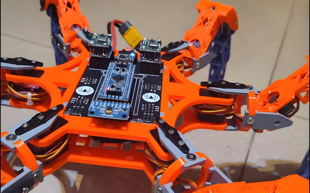
Dans les laboratoires de robotique et les espaces de création des universités, cePCB de commande de moteur de robot sert de carte mère pour les systèmes de contrôle robotiques. Il prend en charge le développement des étudiants et la vérification des algorithmes d'entraînement moteur, y compris FOC. (Contrôle orienté champ) et régulation de vitesse PID.
Scénario 4: Contrôle de la vitesse du moteur du drone
En quadricoptères, ce PCB peut fonctionner comme ESC (Contrôleur de vitesse électronique) tableau de commande. Il convertit les commandes du contrôleur de vol en signaux d'entraînement du moteur, obtenir un contrôle de réponse à grande vitesse des moteurs sans balais.
Pourquoi choisir le PCB de commande de moteur de robot d'UGPCB?
- Conformité totale aux normes internationales: Les produits sont conçus et fabriqués selon IPC-4101E/21, IPC-6012E, IPC-A-600K, CIB-4555, et UL 94 V-0
- Assurance matérielle haut de gamme: Stratifié Kingboard KB6160A FR-4 avec Tg ≥130℃, UL 94 V-0 cote de flamme, et résistance aux contraintes thermiques ≥ 180 secondes
- Fabrication de haute précision: 0.27 mm ouverture minimale et 0.32 mm largeur de trace minimale pour répondre aux exigences de routage haute densité
- Service à guichet unique: Prise en charge complète de la chaîne, depuis l'optimisation de la conception des PCB et l'approvisionnement en composants jusqu'à l'assemblage SMT/DIP et les tests fonctionnels
- 10+ années d'expérience dans l'industrie: Servir 3,000 clients d'entreprise dans le monde entier
UGPCB est un fournisseur leader mondial de conception de PCB, fabrication, et les services d'assemblage PCBA. Fondé dans 2014, la société s'engage à fournir des solutions PCB de haute précision et hautement fiables à ses clients du monde entier.
Obtenez un devis et des échantillons aujourd'hui
L'UGPCB vous accompagnePCB de commande de moteur de robot projet avec:
- ✅ DFM gratuit (Conception pour la fabrication) rapports
- ✅ Prototypage rapide avec 24-heure livraison disponible
- ✅ Production en volume avec 20%+ taux de rendement supérieurs à la moyenne du secteur
- ✅ Équipe d'ingénierie professionnelle fournissant un support technique
📧Contactez-nous pour un devis gratuit: Visitez le site Web de l'UGPCB pour soumettre vos fichiers Gerber et votre nomenclature. Recevez un devis automatisé de pointe.
📞Ligne d'assistance: Contactez-nous via le chat en ligne ou par e-mail de notre site Web.
Déclaration de source de données
Toutes les données techniques et informations standard citées dans cet article proviennent des sources faisant autorité suivantes:
- Kingboard Laminés Holdings Ltd. — Documentation technique du produit KB-6160A (Informations techniques de la base de connaissances)
- IPC (Association reliant les industries électroniques) — Spécification IPC-4101E/21 pour les matériaux de base pour cartes imprimées rigides et multicouches, Spécifications de qualification et de performances IPC-6012E pour les cartes imprimées rigides, Acceptabilité IPC-A-600K des cartes imprimées, Spécification de performance IPC-4555 pour les conservateurs de soudabilité organique à haute température (OSP) pour cartes imprimées, Manuel des méthodes de test IPC-TM-650, Norme générique IPC-2221 sur la conception de cartes imprimées
- UL (Laboratoires souterrains) — UL 94 Norme pour les tests d'inflammabilité des matériaux plastiques pour les pièces d'appareils et d'appareils
- Base de données de matériaux PCBWay —Paramètres techniques KB-6160/6160A/6160C
- Documentation technique OSHPark — Fiche technique du substrat KB6160A
Clause de non-responsabilité: Les valeurs typiques ci-dessus sont des données de tests en laboratoire fournies à titre de référence uniquement.. Les performances réelles du produit peuvent varier en fonction des processus de fabrication et des environnements d'application..













